Grid Life Touring Cup (GLTC) has rules for three different size wings:
Small – You can use a small wing or spoiler that measures under 250 square inches, and there’s no lbs/hp penalty to using one. You can buy an extruded 135cm wing on eBay for $60 or make yourself a spoiler. I tested both in the wind tunnel, and it’s definitely an advantage over using no rear aero at all.
Medium – If your wing measures under 500 square inches, your car takes only a 1% penalty to lbs/hp ratio. The easiest solutions are a 54” 9 Lives Racing wing, or 55” Procar Innovations. I tested both wings in the wind tunnel, and they are both solid choices.
Large – The maximum size allowed in the GLTC rules is 701 square inches, and incurs a 3% penalty to lbs/hp ratio (or 4% when used with a splitter). There are a number of quality 2D and 3D wings to choose from that are class legal.
The focus of this article is only the mid-sized 500 square inch wings. There are already a couple good aftermarket wings to choose from, but I wanted to create a custom wing that makes more downforce than anything currently available. The way I’ll do that is the following:
By maximizing the wingspan to chord ratio, for a particular car.
By choosing an airfoil that has the most downforce.
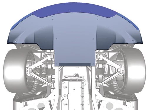
By creating a 3D shape that is customized to the car’s roofline shape, at the ideal wing height and setback distance.
By making it very stiff and light. I made this from foam and fiberglass, and the end result is half the weight of an aluminum wing, and only slightly heavier than carbon.
Dimensions
Since this wing is completely custom, I can make it any size I want. When designing a wing for a car, the general rule is to go as wide as the rules allow, which reduces relative losses from wing tip vortices. Many people have heard the concept of a high aspect ratio wing, and making the wingspan as wide as the rules allow, you get the highest aspect ratio.
This particular wing is designed for a Miata, which puts the wingspan at 64″ max. For a 500 square inch wing, this defines the chord at 7.8″. (For a 700 square inch wing, I’d use the same wingspan and make the chord 11″.)
Airfoil
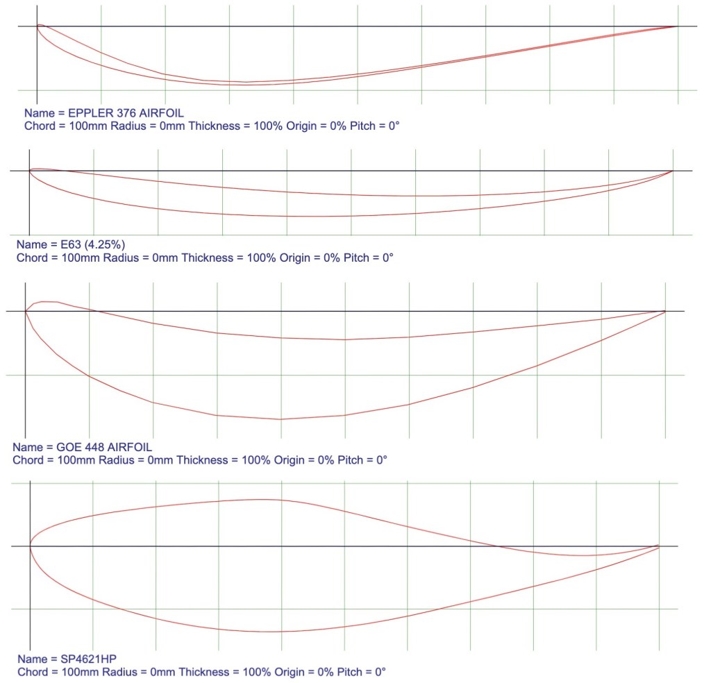
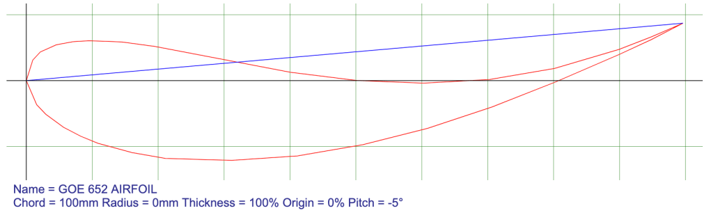
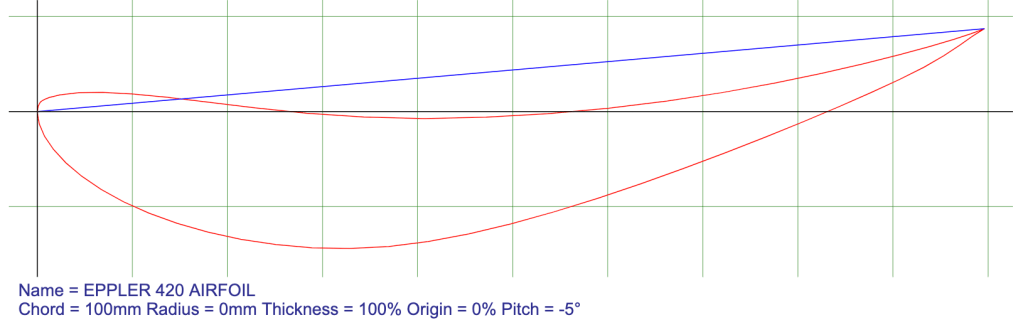
The aviation airfoil with the most lift at low Reynolds numbers (low speed or small chord – same thing) is the Selig S1223 and S1223 RTL. There are several scientific papers written on the Selig S1223, and you can chase those down if you want confirmation. These scientific tests were all done on aircraft, and cars are different.
A proper motorsports wing can have even more downforce, because it doesn’t have to fly. A bunch of research was done on this by Enrico Benzing, and I refer you to my article on Car Wing Comparisons for those conclusions. There’s been additional research into car wings, and one that is particularly good is called the MSDH.
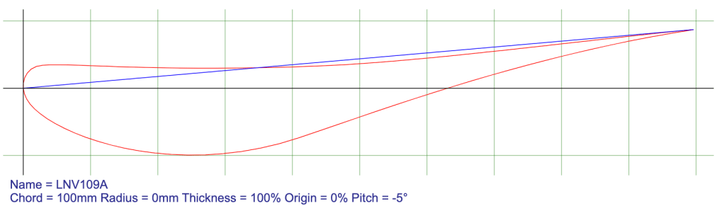
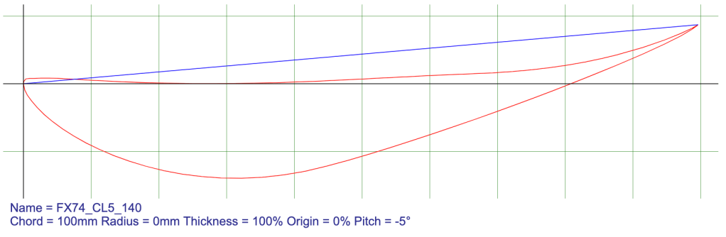
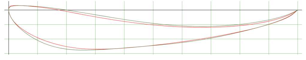
The MSHD airfoil is a lot like the Selig S1223 in shape, but has more camber. I traced the two airfoils onto a piece of paper, and the MSHD looks like someone just pushed down on a S1223 and increased the camber. The airfoil shapes are otherwise very similar.
3D shape
When you extrude a wing from aluminum, it comes out as a 2D shape. When making a custom wing from composite materials, there’s no reason to build a 2D wing.
Cars have cambered rooflines, and so air comes over the center of the roof at a different angle that at the sides. For example, on a Miata, air going over the middle of the roof comes down at a 5-degree angle. Towards the sides of the roof the angle is 7 degrees. And the area outside the wing stands is at zero degrees.
If you set a 2D wing to 10 degrees angle of attack (AOA), that means there are parts of the wing that are at 15 and 17 degrees, which on most airfoils would stall. Stall means air separates which results in more drag and less downforce. When airplane wings stall, they fall out of the sky.
If you set a 2D wing at say 3 degrees AOA, the middle of the wing is at 8 to 10 degrees, which is ideal. But you do lose a little bit of downforce at the ends of the wing, which are only at 3 degrees. So ideally the ends of the wing should be twisted downward so they are in the same 10-degree angle.
The angle that air comes down the roof different at different heights, and setback distances. I made a tool for measuring that, and so I know the exact shape of air as it hits the wing. I turn, this allows me to design a 3D shape that makes the most downforce over the entire wing.
On paper, a 3D wing calculates to about 5% more downforce than a 2D wing, which results in a 14% better lift/drag ratio in free stream air. (Free stream data is worthless, I only include that here because everyone else does.) 5% more downforce is not a huge difference, but if you’re limited by 500 square inches, you need to optimize every inch of it.
Fusion 360 rendering and foam construction by Alyssa Merrill.
Construction
The wing is constructed of foam and fiberglass. Carbon fiber would be better, but for a prototype, the increase in cost and complexity isn’t worth it. I used biaxial fiberglass and silica microspheres to create a strong and lightweight composite.
Biaxial fiberglass over foam.
This is a essentially surfboard construction, and weighs just 5.5 lbs. It supports my full body weight, no problem. It has some flex to it, but is way stronger than I’d anticipated, and I certainly overbuilt it.
Gurney flap
Most 3D wings have expensive Gurney flaps made out of carbon fiber. This is necessary because the rear edge of the wing is also a 3D shape, and so you can’t just slap a piece of angle aluminum on there. But I spec’d this wing to have a straight line across the rear of the wing, so that it would be easy to add a wicker (or even a second element).
The general rule in aviation is that Gurney flaps are 1-3% of the chord. Smaller is usually more efficient for airplane wings, but we are talking cars here which go slower and have terrible aerodynamics. Using a larger gurney flap makes the wing itself less efficient, but makes more downforce, which in turn makes the car as a whole more efficient.
For cars, 1/2″ Gurney flaps are the most common. This works out to 6.4% of the chord on this wing, which is a little large, and if I could find 3/8″ locally I would have used that instead, as it would result in a 5% chord wicker.
I tested the wing with and without a Gurney flap, and while the wing was 11% more efficient without the wicker, the L/D ratio of the entire vehicle was 12% better with it on. In this restricted 500 square inch size, you definitely want the wicker.
Wind tunnel testing
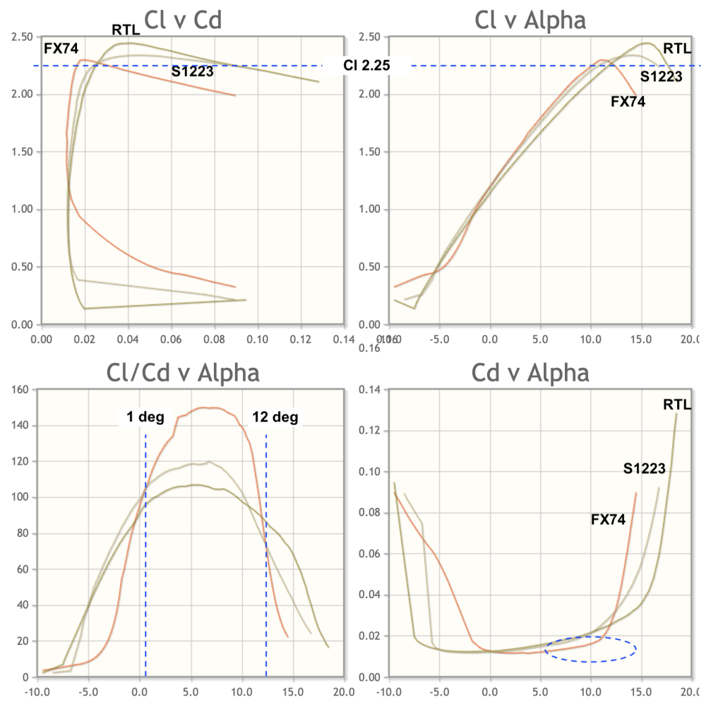
I tested three 500 square inch wings in the wind tunnel, and the MSHD was the clear winner. It’s difficult to say how much of the performance is from the advantages of the MSHD airfoil, the higher aspect ratio, or the 3D shape. (This was tested on a Veloster, not a Miata, but the roofline is similar enough that the 3D shape conferred some benefit.)
Note temporary wing mounts, end plates made from street signs, and a Gurney flap fastened with duct tape.
By fully optimizing the MSHD wing with a Gurney flap and the best performing end plate I tested, it’s possible to outperform a standard 701 square inch wing. I was surprised by this result, and it shows how important it is to customize aero to a particular car and rule set.
To recap the benefits of this wing.
The MSHD airfoil is designed for motorsports applications and has the most downforce of any airfoil I’m aware of. This results in the greatest lift/drag ratio of the vehicle.
The wing can be built custom to any car or rules specification. By using a 3D shape that conforms to the shape of the roofline, the wing can make the maximum amount of downforce across the entire wingspan at any height or setback distance.
The wing is composite structure that is both strong and light, reducing weight and polar moment of inertia.
Am I selling these? No. Or at least not yet. I might sell prototypes that I’m no longer using for testing, or make a one-off for a friend. But I have zero interest in dealing with material shortages, shipping problems, irate customers, and all the other crap that goes along with being a manufacturer. Hopefully I’ve provided enough information for DIY wing builders to go on. So get on with it.
I’m having my right knee replaced tomorrow. My previous operation was a temporary measure to correct for 9.9 degrees of negative camber, and I knew that eventually the arthritis and pain would get to be too much. I just felt like it was a couple years away, so I was a little surprised by how immediately necessary it became.
Some of the hardware that holds me together. Both knees are the same.
The reason I’m having it done right now has everything to do with aerodynamics: Car aerodynamics and tree aerodynamics.
My wife went on an African safari for a couple weeks in July, and so I had some time on my hands. I didn’t have anything planned, but I’m also not one to sit around.
Wife + safari = A2
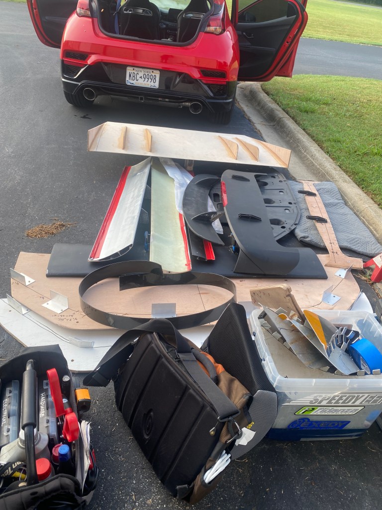
So I suddenly decided it was necessary to rent time at the A2 wind tunnel and test aero parts. But my Miatas are out of commission and I didn’t have that much to test on the Veloster, and so I spent the next week building aero parts.
My race barn has a downstairs area dedicated for cars and bikes. The tools, welder, hardware, etc., are all down there. The upstairs is my wood shop, where I build most parts, do fiberglassing and painting, etc. I went up and down those stairs more than 100 times per day building and fitting and rebuilding parts for the aero test. That put a lot more strain on my knees than normal.
These parts weren’t going to make themselves!
And then, while I was testing my car in the wind tunnel in North Carolina, a wind storm 650 miles north knocked down a bunch of trees. A big willow went down, a couple pines and apple trees, and a silver maple put two holes in my roof. Wind storm. Ironic, innit?
Welcome home!
So I spent a couple days cutting and hauling wood and cleaning up the yard. After which I had two days of coaching at Watkins Glen with PCA. As a result of all that activity, I had no time to rest my knees and I woke up on Friday morning and couldn’t walk.
I literally couldn’t put even a pound of weight on my foot, the pain was excruciating. I had a friend fetch my crutches while I called around to get x-rays and whatnot. Since it had been a few years since my last visit, I couldn’t even get a orthopedic appointment inside of 6 weeks. Thankfully, motorsports came to the rescue.
Warren Wulf is a fellow member at Pineview (and also a classmate from Cornell), and races a BMW. I reached out to him and he got me an appointment that week with Dr Max Greenky. Max does something like 500 knee replacements per year, and after seeing my knee, said that I could get a new one at any time. So I booked an op as soon as possible, and that’s tomorrow.
This will be my third surgery on my right knee, I’ve previously had a lateral release and osteotomy (plates and screws), so I know what to expect regarding recovery, physical therapy, and such. The osteotomy was not my first Rodeo. For whatever reason, my left knee, which had never given me any problems in my entire life, developed the same problem as my right knee. And so Dr Scott Rodeo has done osteotomies on both knees. I’ll need a knee replacement on the left one sometime in the future as well. Gad’s, I think that’ll be my seventh sports-related surgery. I’m falling apart.
FFS Mario, how old are you? I’m 56. I played lacrosse in high school, college, and in a club league afterwards. Probably worse, I skateboarded and did other impact sports my entire life, and have abused the shit out of my body. I don’t count the broken bones. I also have Ehlers Danlos syndrome, and so my joints were predisposed to betray me since birth.
I’m not sure how long the recovery will be. The plate and screws need to come out before the knee comes off, so it’s not a straight replacement. The literature says I’m not supposed to drive for 3 weeks, but you probably guessed that I’m a competitive person, and that just means I’ll be driving at 20 days or sooner. I’m hoping to get back on track in late October.
This gives me some downtime to write, and so I’ll go back through previous articles and inject some wind tunnel test data. I’ll also have to correct a few things I was wrong about (canards), and put an exclamation point on things I was right about (end plates).
This downtime is a good time to Contact Me and ask me aero questions, or just message me in the middle of the day and say yo. I’m also scheduled to be a guest on the RacersHQ podcast, and maybe the Garage Heroes will invite me back.
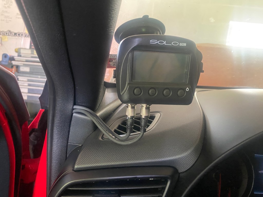
Once I’m able to drive in anger again, I’ll go to Pineview and get more Aim Solo data on the new track. I’m not sure if I’ll update the track guide, but I want to put something up on this site in the meantime.
My brother was supposed to visit, but because of injuries of his own (we are identical twins after all), I have four non-transferrable guest passes I need to use this year. If you’ve never been to Pineview and want to check it out, hit me up.
A splitter separates airflow above and below the car, reducing drag and lift by decreasing the amount of air going underneath the car. A splitter also creates downforce via pressure on top of the splitter blade and suction below the undertray. Various things you do on and around the splitter can make it perform better or worse.
When I look at splitters on typical track cars, I see a lot of common mistakes. I tested some of those things in the wind tunnel recently, and have updated this article and turned it into a Top 10 kind of thing.
Now before I dive into that, let me get off my high horse and admit that I’m as guilty as anyone. In the past, I really only considered splitter length and ground clearance, and those were mostly for durability. After taking the JKF Aero course, I have a much better understanding of how splitters work, and I hope to help my readers avoid the same mistakes I made. Here’s my Top 10 of splitter mistakes:
1. Misunderstanding how splitters work
The single biggest mistake people make are not understanding that it’s the underside of the splitter that does most of the work. Splitters are essentially wings, in that they create much more downforce from suction than they do from pressure.
This misconception cascades into a series of mistakes that results in things like people rounding the wrong side of the splitter blade, or completely ignoring the underside.
You’ve seen people who put wings really low on the trunk lid, with the result that very little air it no goes under the wing. There’s also no space below the wing for the low-pressure region to form, and so the wing doesn’t work as it’s supposed to.
A wing mounted too low is a spoiler. A splitter mounted too low is just as bad.
When a wing is mounted that low, it behaves as a spoiler, creating downforce through pressure, and not suction. But it’s the underside of the wing, the suction side, that creates most of the downforce.
Misunderstanding how a wing works is the same thing as misunderstanding how a splitter works. Let’s fix that, starting with…
2. Sharp leading edges
Aerodynamic wings (airfoils) always have a rounded leading edge. Air must flow around either side of the stagnation point at the front and stay attached along the entire surface.
Airfoils come in all shapes and sizes. All of them have a rounded leading edge and sharp trailing edge. Your splitter should be the same.
Sharp leading edges cause flow separation, which results in drag and turbulence. If you want a really shitty wing, turn it backwards so that there’s a sharp leading edge and a rounded trailing edge. You’re not going to do that with a wing, but you might be doing that with your splitter!
In fact I see way more splitters with rounded top edges and flat bottoms than I do the reverse. Sorry, but you all have that wrong; round the underside.
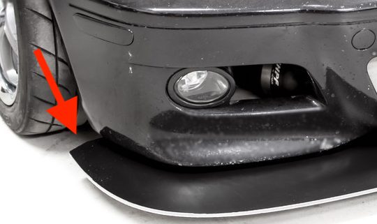
Sometimes sharp leading edges are a consequence of the material, such as when using aluminum or carbon fiber. But if you’re going through the trouble of making a splitter from composite materials, you can certainly go through the trouble of thickening and then rounding the leading edge! When you round the leading edge of your splitter blade, round the bottom of the splitter blade more than the top, obviously.
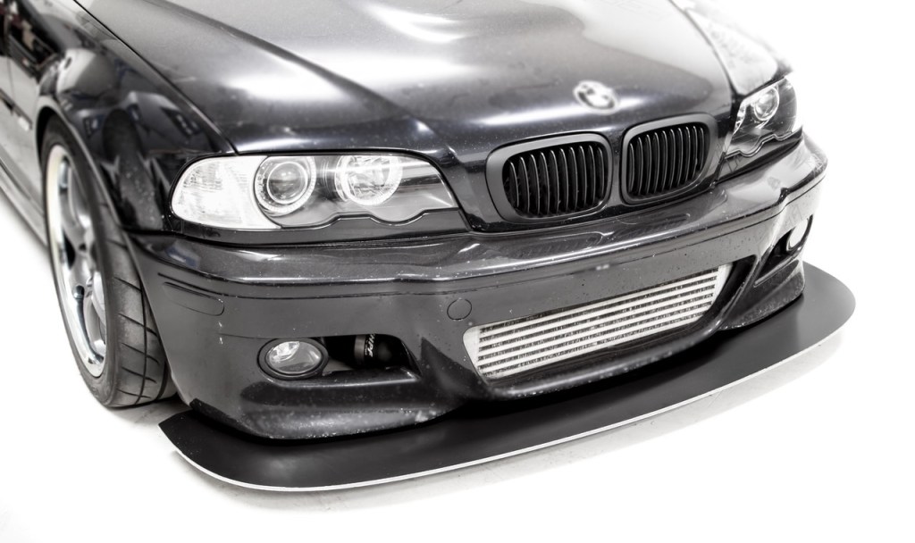
Just say no to sharp leading edges.
On high-end sports cars, I see a lot of aftermarket splitters that are super thin, made from carbon fiber, and costing thousands. Something that expensive makes you believe it works as designed, but that sharp leading edge creates flow separation, no matter how much you paid for it.
3. No height adjustment
Splitters are ground effect devices and the downforce changes up to 250% depending on proximity to the ground. A splitter that isn’t adjustable for height is like a wing that isn’t adjustable for angle.
There was a recent conversation on Trackable Miatas regarding splitter height. One internet pundit gave everyone else the benefit of his inexperience by stating that you should run the splitter as close to the ground as possible. His reasoning was that the splitter keeps making more and more downforce the closer you get. That’s not entirely accurate.
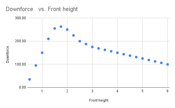
Yes, downforce increases as the splitter gets closer to the ground, and the gain is fairly linear. However, from around 3” to 1.5”, downforce increases sharply, and if you’re going after maximum downforce, that’s where you want the horizontal portion of the splitter (measured with driver, full fuel tank, and at speed).
However, going after maximum downforce also creates a very sensitive car, liable to lose all downforce in an instant. If you go lower than 1.5”, the splitter starts to get flow separation, which results in drag and a drastic reduction in downforce. Ergo, setting your splitter too low is quite a bit worse than having it too high.
This aero map is specific to one car at a certain speed and would be different for other cars at other speeds. Use this as a guideline only.
To put some round numbers on it, let’s say your splitter makes 100 lbs of downforce at 6″ of ground clearance. It will make about 175 lbs at 3″, and max out at 250 lbs at around 1.5″. If you go lower than that, the situation reverses and the splitter loses downforce dramatically until it’s back to 100 lbs at .75″.
To the people who run their splitters as close to the ground as possible, I want to race you. For money.
4. Lacking an undertray
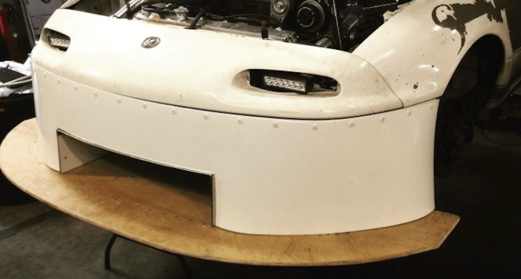
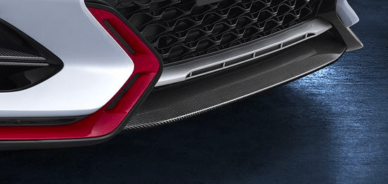
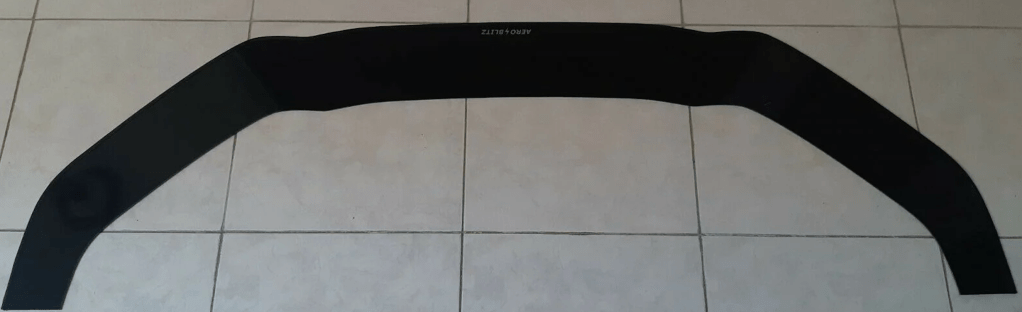
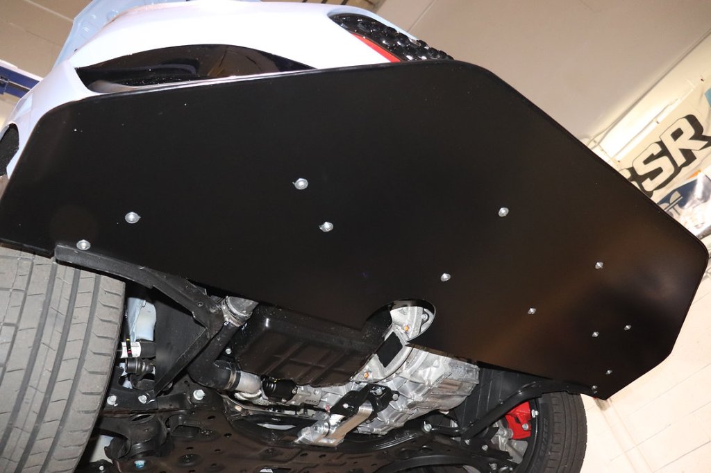
Airdams and front lips don’t create much downforce unless there’s planform area under the car where a low pressure region can form. In other words, the front lip needs to be connected to, and supported by, a horizontal undertray. Factory or aftermarket front lips that aren’t connected to a rigid undertray only create a tiny (negligible) amount of downforce.
On NA Miatas, the R-package front lip is a popular add-on. This will keep some air from going under the car, and in that way can reduce drag and lift. Larger versions like the Garage Vary (GV) front lip also can build a small amount of local pressure on the convex portion, but it won’t be much.
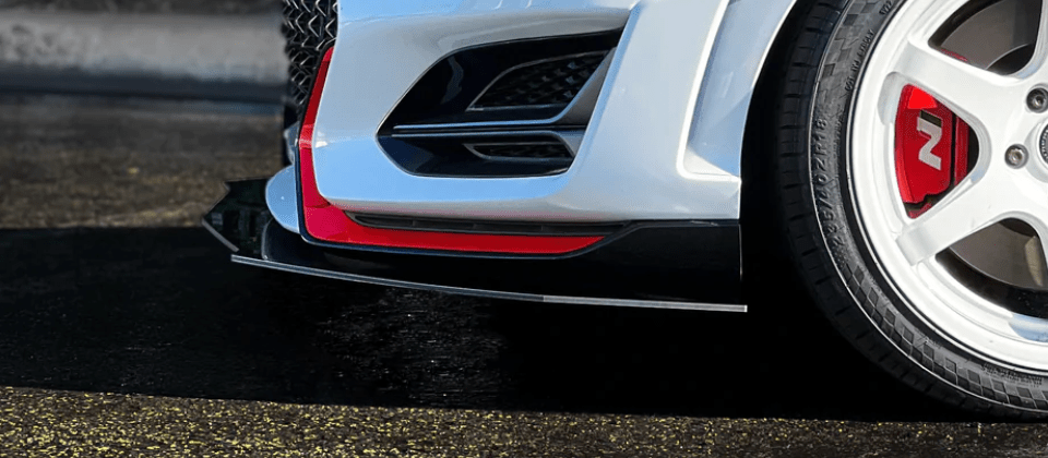
Unsupported front lips look cool, but do very little to create downforce.
This kind of unsupported front lip is the only situation where you’d want to run the aero as low as possible. You won’t lose downforce because you haven’t gained any, and less air under the car is better. But compared to a proper splitter, these cosmetic doodads aren’t really an aerodynamic device, they are just for show.
5. Flexible
Splitters can create more than two hundred pounds of downforce, so the blade needs to be rigid. I see people standing on their splitter blades and that’s an OK benchmark for how strong the lip needs to be. And yet I’ve seen so many amateur splitters (both DIY and aftermarket) that would flex under the weight of my big toe.
Case in point, a guy I met at Miata Day (Canaan, NH) who had never been on track before. Like many street enthusiasts, he had a very “appearance grade” Miata with eBay aero tacked on everywhere. His spitter was so flimsy I could deflect it with a touch. I told him he should remove the “splitter” or he was going to lose it in the first session. He lost it.
Now before you go building a splitter out of 1” plywood so that you can stand on it, note that the low-pressure area is about 1/3 of the way back from the splitter lip. It’s not the front or the top of the splitter that is doing most of the work, so you don’t need to be able to stand on your splitter blade, you just need to keep it from flexing at speed.
6. Shitty materials
Plywood is probably the most common splitter material. Regular exterior plywood from your lumber yard is junk: it’s heavy, has knots and voids, very few plies, and delaminates when wet.
Sometimes you can find a better quality of plywood, such as oak or birch, but often only the outer veneers are better wood and the inside is the same knotty, void-ridden, pine-based shite in the exterior plywood racks.
If you look hard you can get true Baltic Birch, which is a furniture-grade wood with a good strength to weight ratio, and lots of thin laminates. But I’ve seen Baltic Birch splitters delaminate, and suspect the glue is usually the water-soluble type.
To avoid delamination, plywood splitters need to be made out of marine plywood. Marine plywood has different grades, and what the “marine” distinction really means is that the glue is waterproof.
I once ordered a sheet of 3/4” marine plywood from my local specialty lumber store. What I got was a 80-pound slab of 5-ply Douglas Fir. I returned it immediately. A similar sheet of Meranti plywood weighs 64 lbs, has 11 plies, and is stronger.
The ideal wood is certified boat building plywood. There are two grades, BS1088 and BS6566. 1088 is an appearance grade, more expensive, but generally easier to find. 6566 isn’t as pretty, but is built to the same specification. The BS specification is void free (X-rayed, I believe), and tested for delamination by boiling in water.
I like Meranti BS6566 Aquatek made from mahogany. There are other BS-certified plywoods made from sapele, gaboon, and other hardwoods, and some of them are lighter than Meranti, but none of them are cheaper or better. For example Okume is about 10% lighter than Meranti, but it’s also more flexible and more expensive, and so I don’t think it’s better for splitters (for boatbuilding it’s superior).
I make my splitters by laminating two sheets of 6mm so that I can add curvature. For a flat splitter, I’d spec 15mm for the extra durability.
You can also make a splitter from aluminum, Alumalite, carbon fiber, etc. Sheet aluminum is heavy and has a sharp leading edge, and I wouldn’t build a splitter out of solid aluminum.
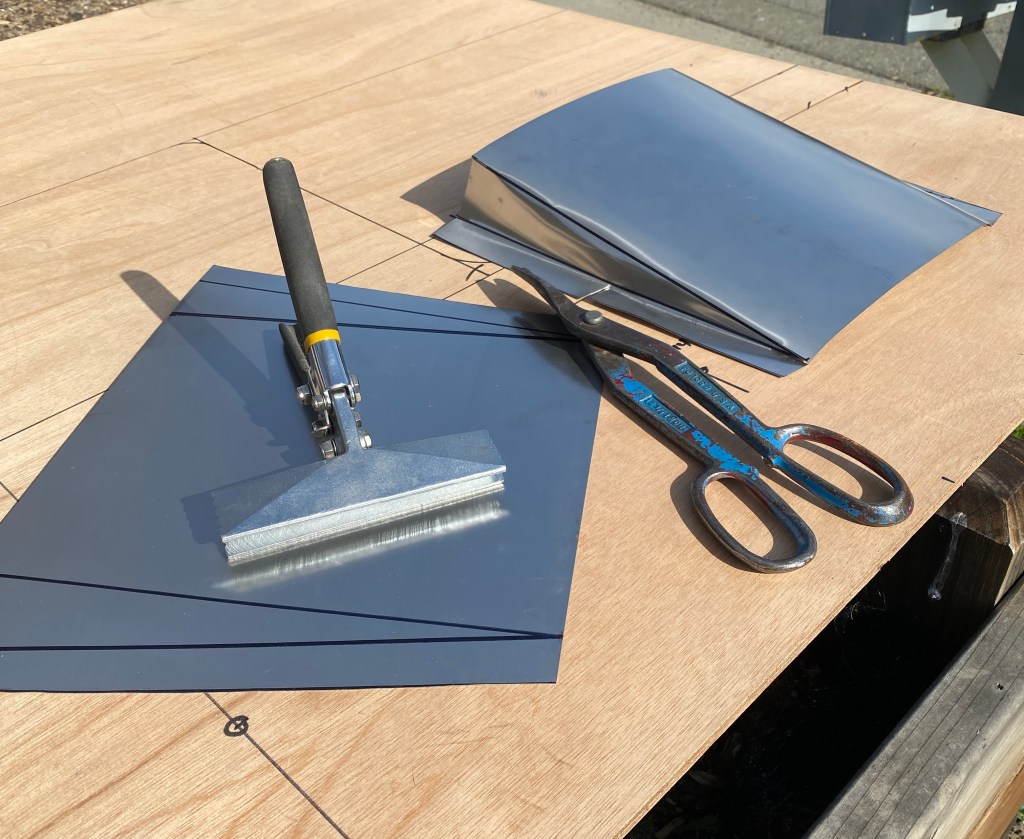
Alumalite is a common splitter material, it’s two very thin layers of aluminum bonded to a lightweight hollow plastic core. The material is mostly used for street signs, but has wound up underneath a lot of budget race cars as a flat bottom, or as a splitter.
I have an Alumalite spoiler, and I’m not sure why people love this material. You can’t weld it, it doesn’t glue well, it’s more difficult to work with, and it’s not particularly light. A square foot of 10mm Alumalite and 9mm Meranti weigh the same and the Meranti is stiffer, more durable, easier to fix, and half the cost.
If I had unlimited funds I’d build a splitter from carbon and Kevlar, but for my current situation, I don’t think a couple pound savings is worth it.
7. Unused ends
Time-attack cars often have splitters with “hammerhead” extensions on them, which are wider than the car. When properly constructed, these extensions are wing shaped in profile and cause air to move upwards and away from the car, which creates pressure on top and (more importantly) suction below the splitter extension.
On Miatas, I often see smaller splitter extensions that are basically unused splitter material, they are horizontal and don’t change the direction of airflow. Here’s the thing: if you don’t change the direction of airflow, you aren’t doing dick. A flat horizontal plate just causes drag. Why have a splitter that’s wider than the bodywork if you aren’t using that in some meaningful way?
Exposed flat splitter blade does nothing.
I sometimes see these exposed splitter ends coupled with a spill board on the outside edge. The first thing I always think is, “this is going to get caught on grass and rip the splitter off.” For the life of me I don’t understand why people do it, as there are better uses of that space.
I’m not saying it’s useless: a spill board acts as an air curtain, directing air along the side of the car. This can reduce the wake of the front tires, and reduce drag of the car as a whole, but the drag reduction is tiny. On a street car doing 15k miles a year, reducing drag can be useful.
But for a race car, it’s far better to kick the air upwards or out sideways. If you have some extra width on your splitter, by all means make a vertical back wall. This will create a high pressure zone on the top surface, generating downforce. That spat will also send air up and out, creating a suction zone under the splitter extension, creating even more downforce.
I wrote about this in Splitter Length and Side Fences and you should read that if you haven’t. The gist of it is that MacBeath tested spats of different shapes and sizes in a wind tunnel, and a vertical spat increased front downforce by 150% and had the best L/D ratio. The car was an Integra, not a Miata, but you can imagine the results would be pretty similar. Now that’s using the exposed splitter end to good effect.
You can put a fence on the outside of that vertical spat, which will capture more local pressure (more downforce), or leave it bare, which will kick air out sideways. Directing air outwards will help prevent air from intruding beneath your splitter, and helps extract air from the wheel arches, which in turn makes your splitter more effective.
Whether it’s better to kick air up or out is debatable. There are downstream effects of both, which you could estimate in CFD or test on in a wind tunnel. But surely, however you direct the air off that extra splitter width is better than leaving it unused.
8. No diffusers
Splitters create downforce by accelerating air through a restriction, which creates a low pressure region under the blade. You can increase the suction if you allow air to expand upwards behind the lowest point of the blade.
The easiest way to do this is to curve the entire splitter upwards at the rear. Many racing rules state that splitters must be flat, but they also give you some wiggle room. In the wind tunnel, my flat splitter made 134 lbs of front downforce, and one with a 5-degree curve made 195 lbs.
If the rules allow it, or if you simply have a track car unbound by racing rules, absolutely you want to curve the entire trailing edge of the splitter upwards at a 12 degree angle. It’s such an advantage over a flat splitter, it’s not even funny.
If you have a flat splitter and can’t curve it, then install splitter diffusers (splitter ramps) underneath the splitter. The concept is the same as a diffuser behind a car, it allows air to expand, which accelerates the air in front of it, creating more suction.
Splitter ramps can be 3D-printed into a continuous curve, or just an angled ramp of sheet metal. If you go the latter route, don’t exceed a 12-degree angle, or you risk flow separation. If you don’t have an angle meter, that’s about a 2.5” rise over 12” run.
Splitter ramps from scrap aluminum.
If you buy 3D-printed splitter ramps, beware of what you’re buying. I just saw someone in the Miata 3D printing group who is trying to sell a product with an 18-degree slope. That’s too steep and will cause flow separation. His price was also too steep, considering you can make your own out of scrap metal for a dollar.
Occam’s Racer splitter diffusers.
Where you place the splitter ramps depends on where you can get the required height for them. Generally you can dump air into the wheel wells as there’s room to work with and it’s a fairly lossy area to begin with. But if you dump air into the wheel wells, you need to extract it.
9. Suction management
Nature abhors a vacuum; if you have suction underneath the splitter, then air from everywhere else is at a higher pressure and wants to hate on it and spoil the party. To make the splitter perform at its peak, you need keep the bad air out. And yet, I often see cars that make no attempt at keeping air from bleeding air into the low-pressure zone beneath the splitter.
The largest source of this air comes from the engine compartment. Think about it: all the air that goes through the radiator has to go someplace, and it often goes under the car. If this air can wrap around the sides of the splitter, it ruins the suction you’ve worked so hard to create. So the best way to mitigate this is ducting the radiator and using hood vents. Hood vents aren’t just for cooling (or looking cool), they make downforce.
Vents on top of the fender and extractor vents behind the wheels will also relieve pressure in the wheel arches that’s trying to get under your splitter. If you have splitter diffusers, you’ll need as much venting as you can get.
Both hood vents and fender vents should ideally eject air upwards, thereby creating an opposing force, downforce. Unfortunately the downstream effects of these vents is turbulence, and with that, a loss on rear wing performance. But since most cars are front limited with respect to downforce, it’s a good tradeoff, just use more wing.
Downstream effects of venting.
Getting back to the situation under the splitter, another area of loss is air that comes in through the wheel spokes. Optimizing this area doesn’t provide a lot of benefit, but it’s worth going after if you’ve done everything else already. If you take the JKF Aero course, he goes into a lot of detail on caketin covers, and it’s beyond the scope of this article, so if you’re looking for the last bit of performance, take the course.
10. Cooling ducts too low
So far I’ve concentrated only on the underside of the splitter, but the top of the blade also matters. There’s a recirculating bubble of high pressure air on the top of the splitter blade, and you want to hold it there. For the people that ignore what’s happening underneath the splitter, this is the part of the splitter that matters to you.
If you place vents (radiator inlet, intercooler, brake ducts) low down on the airdam/fascia, that high pressure air goes through the holes instead of being held on the blade. Directing air into ducts might be beneficial for cooling, but it reduces the downforce.
A radiator opening this low will make less front downforce, and air has to bend sharply upward to get to the radiator. Radiator openings should also have rounded corners for attached flow.
The other problem with a radiator duct that’s too low is that air has to bend upwards to get to the radiator. If that angle exceeds 12 degrees, you’ll get flow separation (drag, turbulence, loss of velocity and cooling ability) inside your air duct. You’ll get better cooling and less drag with a straight shot to the rad, and you’ll create more downforce by holding pressure on the splitter lip.
If you’re racing in a series that doesn’t allow you to use a splitter, but allows an undertray, you could use an arrangement like the pic above (imagine the airdam and undertray being flush, with no splitter extension). This would allow you to hold some pressure on top of the undertray and make suction below. In that case, I’d certainly put the radiator opening at the bottom and trade downforce for the consequences.
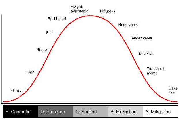
Grade your splitter
If I was to throw a grade on the average splitter I’ve seen on the average Miata, I’d give it a C. On other track cars, the average is a D+. I know that grades are supposed to fall on a bell curve, but I grade strictly, and you non-Miata people suck at aero.
Grade F: Flimsy splitters or front lips, usually bought on Amazon or eBay. These do nothing but look like a splitter.
Grade D: A misunderstanding of how splitters work results in splitters that are optimized for the top side, not the underside. They are are too high, have sharp leading edges, and are flat. They might have a spill board on the outer edge, which does fuck all of nothing for the underside.
Grade C: A splitter gains downforce through suction, which is achieved primarily through proximity to the ground and using diffusers and/or curvature to accelerate the air underneath.
Grade B: With great suction comes great responsibility. You need to extract the air upwards and outwards using hood vents and fender vents, and also by directing air up and out on the blade using canards, spats, and wickers.
Grade A: Mitigating losses from high-pressure air around the wheels and tires is the last frontier. Tricks like spinning a vortex into the face of the tires and caketin covers are ways to achieve this grade.
Splitters on a bell curve.
Your splitter sucks!
The purpose of this article was to point out the most common mistakes people make with splitters, and to tell you that your splitter sucks. Literally. It sucks to the ground and that’s where most of the downforce comes from. I see a lot of aftermarket and DIY splitters that could be easily modified for less drag and considerably more downforce.
Now that you know that your splitter sucks, take a look at it with fresh eyes and ask yourself how you can optimize what’s going on underneath. What can you do to make your splitter suck even more?
If you follow my website, you know I’ve been building aerodynamic parts and testing them for a few years. Much of that time I was focused on Miatas, but the development, testing, and conclusions apply generally to all road racing vehicles. I’ve recently started testing in a wind tunnel, and wrote a report which I’m selling for a modest fee.
The report is over 50 pages and contains numerous pictures and tables, racing simulations, and analysis of the results. The report is aimed at the average racer who has no patience for mathematical formulas and just wants to know what works.
All of the data is presented as coefficients of lift and drag, which is useful to aero nerds and anyone who uses a racing simulation program. But all of the data is also translated into pounds of downforce and drag, and gains or losses in horsepower.
For each aerodynamic part I also do race track simulations on an autocross course and a road course, so that you’ll know the most important thing: how much faster you’ll go. At the end of the report I put various parts together into logical “builds” that comply with the rules and classes of different racing organizations, like Grid Life, NASA, and SCCA. And I also run simulations at more race tracks.
Here’s what you get in the report:
Aerodynamic principles as succinctly as I can put them, and only as they relate to the data in this report.
Three splitters with identical front size and shape, but very different undersides resulting in huge gains in downforce and drag reduction. I’ve never seen anyone test splitter curvature, so this is all new.
Canards in three different locations, with results that vary from 11 pounds of front downforce to over 85!
Hood vents, showing the drag and lift on cars with and without aero.
Open vs closed windows, and how that affects a car with and without aero. And how to easily reduce the negative effect of open windows by half.
Two different spoilers compared to a bare roof without a spoiler. Drag, lift, and lap times as normal, but also MPG.
250 square inch wing vs spoiler, for cars that race in GLTC.
Three different 500 square inch wings, with and without Gurney flaps. This shows the effectiveness of different airfoils, and how each changes with the addition of a wicker. The wing size is especially useful for cars that race in GLTC.
How does a low-Reynolds high-lift aviation airfoil compare to a motorsports wing? I test a Selig S1223 vs 9 Lives, PCI, and MSHD to find out.
End plate shape and its effect on wing vehicle performance. The results don’t correlate to CFD, and they aren’t what you’d expect.
Diffusers work great if your car has a smooth, flat underbody, but how do they work on a regular road car? I build a diffuser designed specifically for use without a flat bottom, and give you the dimension of it, and the results.
Base car performance, hatchback aerodynamics, drag and lift, and race simulations on different tires, and more.
Fill out the form and click then click the link to download the report. If you’ve bought me a coffee, use the password for a $5 discount.
If you close the browser tab before you click the link, you won’t get the report. In that case, contact me and I’ll send you the link.
Please don’t share the report, it’s a lot of money and effort to build and test the parts, and a lot of analysis and writing to present the information in a meaningful way. I firmly believe you won’t find a cheaper way to go faster than by using the aerodynamic tricks and tips within this report.
If you feel this information was worth the money, I’d appreciate it if you leave a comment. If you don’t feel that way, tell me why and I’ll refund your money.
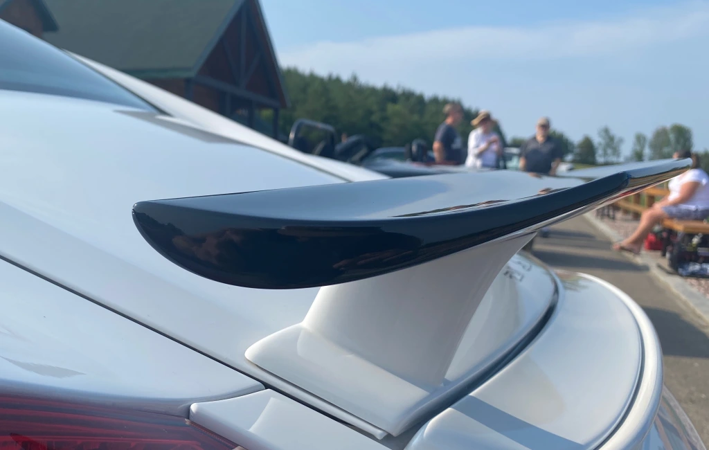
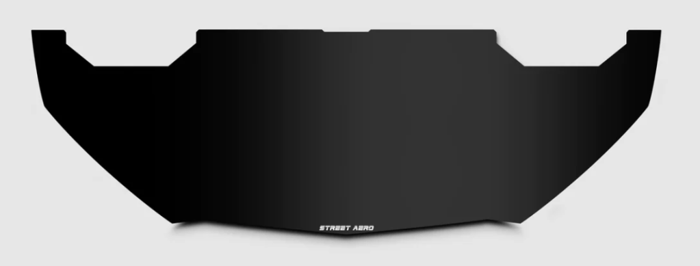
I wanted a proper wing for my Veloster, that makes enough downforce to match my splitter. The OEM wing on a Veloster N isn’t really a wing, because it doesn’t have an airfoil shape. It’s not exactly a spoiler either, because air goes both on top and underneath it. What the wing/spoiler does is straightens out airflow and cancels some of the lift created by the downward-sloping roof. It makes downforce, but not enough to counteract a decent splitter.
There are a lot of good off the shelf wings, but I wanted to make my own (again). This time I opted for a Selig S1223 airfoil. There’s a higher lift version called the S1223 RTL, but it really only has an advantage at the steepest angle of attack, and otherwise has less lift.
Designing aero for FWD hatchbacks is new to me, and there’s definitely some guesswork involved. As a rule of thumb, you want the widest wingspan allowed in your racing rules, because this lessens the detrimental effect of wing-tip vortices. Most rules limit wings to body width, which on a Veloster N is 71.3″ (181cm). That’s a large wing, but because front-wheel drive cars have proportionately less weight on the rear of the car, they don’t need as much rear downforce.
I could have made a high aspect ratio wing the full width of the car, but this would result in a very small chord. At Reynolds numbers under 2 million, wings are actually more efficient with more chord, not less. So this is an area where I’m totally stumped: is a narrow wingspan with more chord better or worse than a high aspect ratio? I’ll have to test this one day.
One thing is for sure, a longer wingspan is a pain in the ass (and often a pain in the head) when you work on the car. The number of times I’ve bonked my head or run into an end plate…
So in the end, I decided on a wing with a 53.3″ (135cm) wingspan and 11″ chord, with a total area of 583 square inches. That’s the same total area as a 64″ 9 Lives Racing wing that you’d see on a Miata, which kinda makes sense, as a Miata and Veloster have the same amount of weight on the rear wheels.
S1223 aluminum form used to trace out copies.
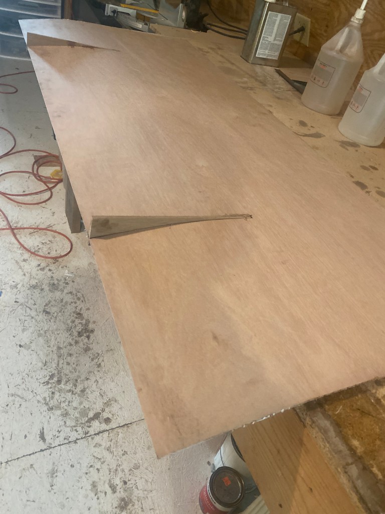
I traced the S1223 airfoil shape onto Meranti Hydrotek (BS6566) plywood scraps I had lying around from splitter projects, and then cut them out on my band saw.
Wing construction
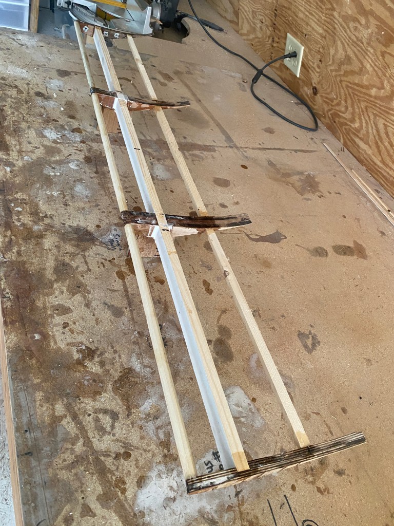
I began by gluing up the ribs to a central spar. You can see in the pic that the spar is notched into the wing mounts and end plates. I then glued a wood dowel to the front and a thin spar towards the trailing edge. This skeleton provides the basic structure and shape, so that thin plywood panels can be glued on top and bottom.
Ribs and spars, the old-fashioned way.
The plywood itself is very thin and offers little strength, but the whole outside will be covered in fiberglass, which is where the strength comes from. This construction style is called a torsion box, and is used on everything from airplane wings to the doors in your house.
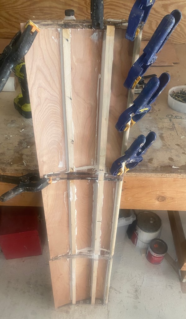
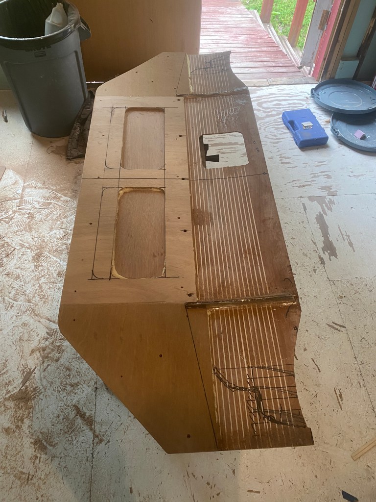
The wing mounts are on the bottom, and an integral part of the structure, so I had to laminate the bottom of the wing in three pieces. I did one at a time.
Gluing the last of three panels that form the bottom of the wing.
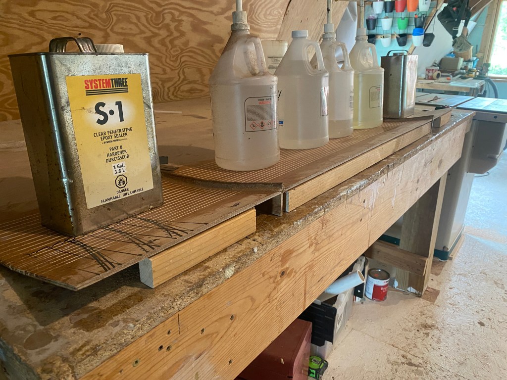
After gluing and filleting the bottom panels using epoxy and microspheres (filler), I flipped the wing over and glued the top of the wing. You might be wondering about the plywood I use for the upper and lower skins. Big box lumber stores like Home Despot and Lowe’s get pallets of wood that are strapped down with a very thin plywood sheet over the top to protect the wood below. This thin 3-ply plywood is so flexible you can almost bend it in a circle. There’s no SKU for it, and they’ll give it away if you ask nicely.
I can make a couple wings from a sheet of this plywood. But while it’s free, it isn’t easy to find, because it doesn’t come on every pallet of wood, and they typically throw it away. So make sure you check back often or make friends with the store manager, this shit is gold.
Gluing the top veneer. Those clamps are made from a PVC tube cut into rings with a slit in it.
After gluing on the plywood panels I wrapped the whole thing in fiberglass fabric. After gluing the wing up, I noticed the rear edge of the wing was a little wavy. Damnit. I don’t think this is a big deal for a single element wing, and I’ve even seen some wings that have a wavy rear edge on purpose. But I’m going to add a double element in thr future, and it needs a straight trailing edge for that.
The solution was to clamp and glue a 1/2” (13mm) Gurney flap to help flatten it out. I wasn’t sure I was going to add a wicker on this wing, but it was the obvious solution to this problem and now it’s not coming off!
The wing weighs 6.6 lbs (3 kg) which is pretty light considering how stiff and solid it feels, and this includes the gurney flap, end plates, and bottom mounts. That’s less than half the weight of an aluminum wing of the same size, and probably a pound heavier than a $3000 carbon wing. The bigger difference is my material cost is less than $100.
Wing mounts
While building the wing I spent a lot of time thinking about wing mounts. Many racing rules limit the height of a wing to roof height, but they usually give hatchbacks a bit more room, and 5-8″ above the roof is common. That’s plenty of height considering how much the roof slopes back in the rear.
On a sedan, you typically mount a wing with about 1/4 of the wing overlapping the rear of the trunk. On a hatchback, you need to get the wing a bit further back. The wing needs area below the wing for the low-pressure region to form, and the rear window glass is in the way.
Because I don’t know a lot about hatchback aerodynamics, I want to be able to adjust the wing not only for angle, but for height and setback distance. Because of the high roofline, being able to make adjustments here could be critical.
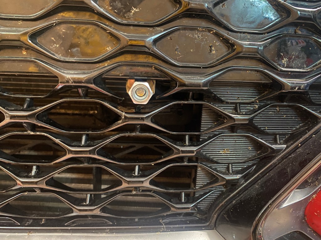
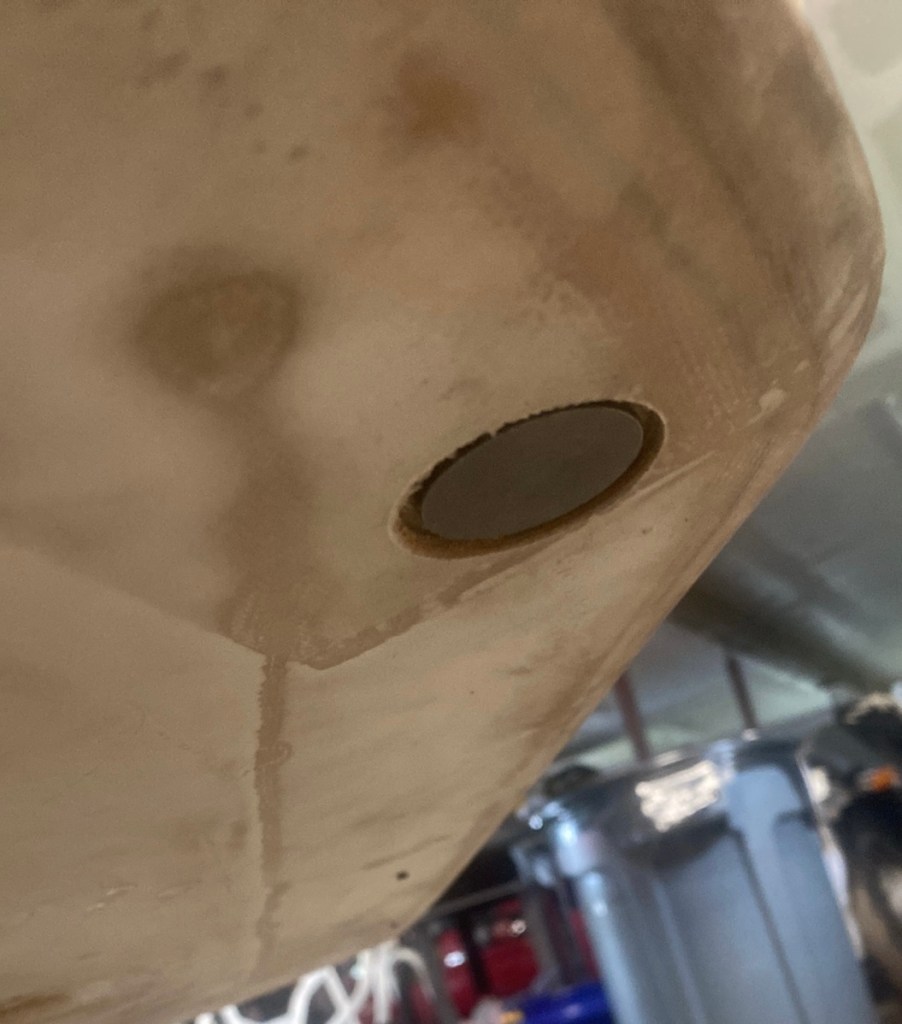
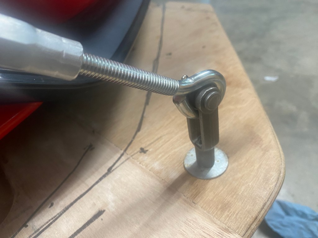
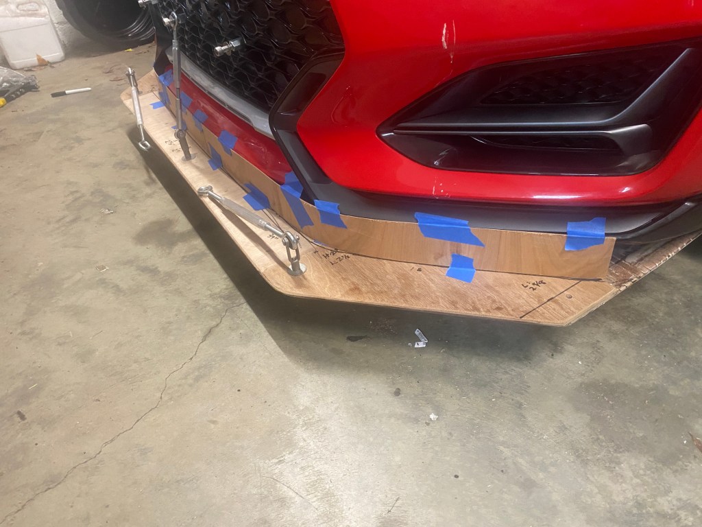
For this reason, I built a four-point mount with a long, flat top. This allows me to move the wing fore and aft 6”. I also put a 8-degree fixed angle into the top of the cradle mount, and so moving the wing forward or backward changes the height 1”. The wing itself has built-in uprights with an additional 2″ of height adjustment, so altogether I can move the wing forward or backward 6″ and up or down 3″. For the lowest drag settings, I zero out the wing and move it low and forward. For the highest downforce configuration, I’ll move the wing rearward and up. Makes sense to me, but let’s see how it works.
These are temporary wing mounts I used in the wind tunnel. Note that the wing is at roof height, even if it looks really tall from this angle.
Airfoil data
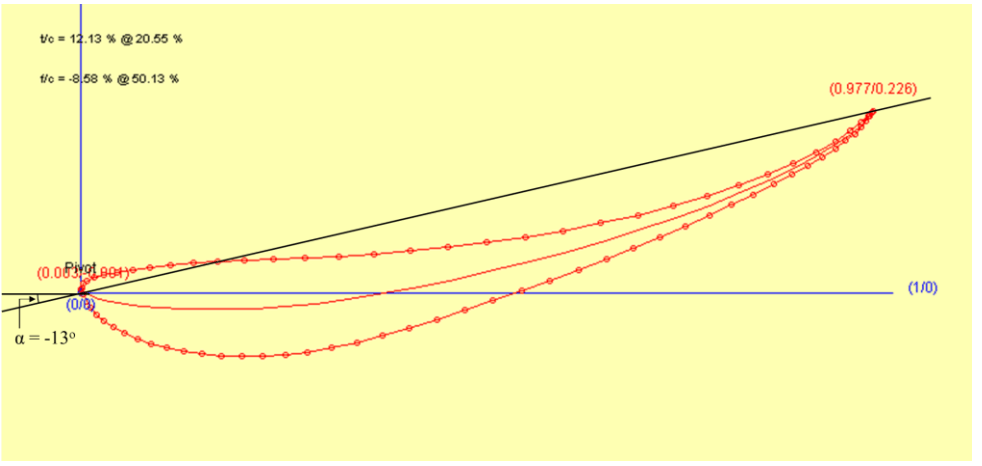
The following images come from Airfloil Tools and show the S1223 data at 500k Reynolds, which is 57 mph (92 kph) for an 11″ chord wing.
The first graph is the coefficient of drag (Cd) at different angles of attack. The lowest drag setting is right at zero degrees, but anywhere between -2 to +2 degrees is going to be indistinguishable. From 3 degrees to 12 degrees drag increases linearly, but then really spikes upwards at 13 degrees as flow separations occur.
Coefficient of drag at various angles of attack. Best to stay between -2 and 12 degrees.
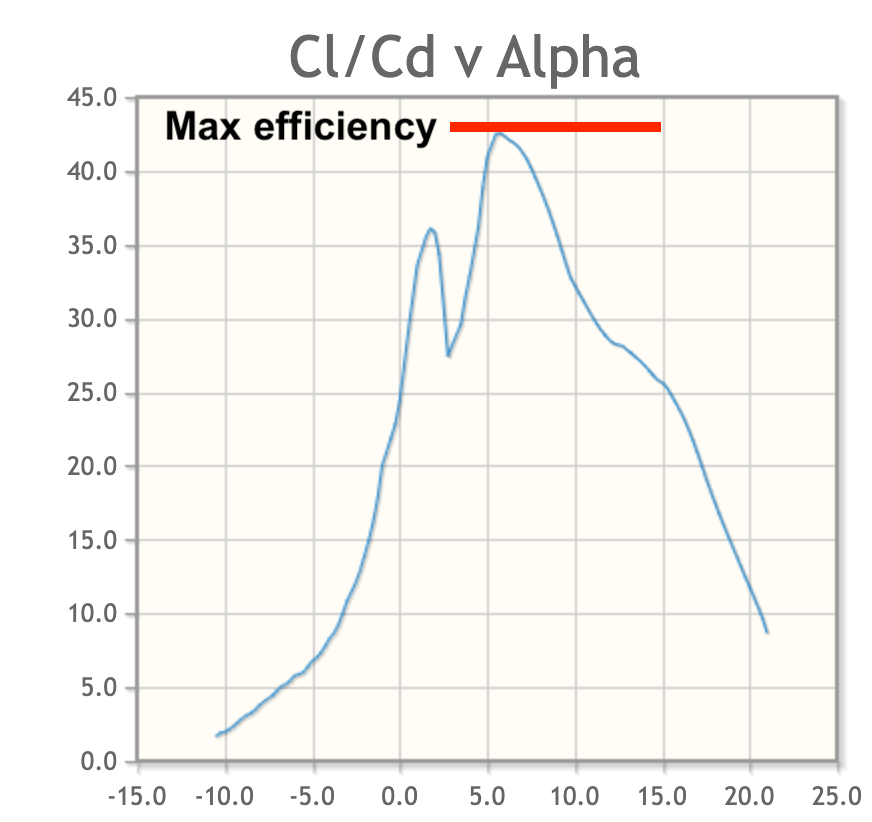
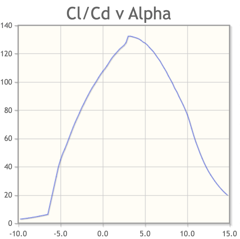
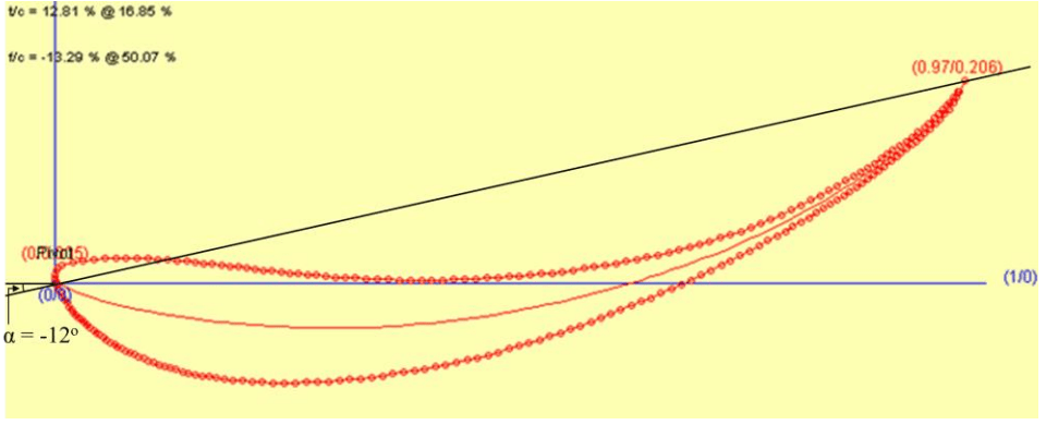
In the next graph you can see the best lift/drag ratio of the wing is around 5 degrees. This isn’t hugely important, since it’s the lift/drag ratio of the vehicle that matters, not the wing. Anyway, it’s an interesting data point.
Best efficiency of the wing is around 5 degrees.
The most important graph is the coefficient of lift vs angle, because you can use that to estimate the amount of downforce at different angles of attack. This wing ranges between .5 Cl at -2.5 degrees to 2.4 Cl at 13 degrees
The arrows show the coefficient of lift (Cl) at least drag (0 deg), max efficiency (5 deg), and max downforce (13 degrees).
Therefore, I’m going to spec a working range of 0 to 12 degrees, and use a baseline of 8 degrees. Now, because the roof also slopes downward at around 8 degrees over the roof extension, that means I’m actually setting the wing to zero degrees in relation to the ground.
Given all this data, it would be useful to have five settings for wing angle: 0, 3, 5, 8, and 12 degrees. In terms of pounds of downforce, if the wing is making 120 lbs of downforce at zero degrees, then each setting would be about +25 lbs of downforce. I don’t think settings in between those will be super useful, as I don’t think I could feel a difference of having 12 pounds more or less in the trunk.
Angle
LbsDF
Zero
120
3 deg
150
5 deg
175
8 deg
200
12 deg
225
Wing angle and relative pounds of downforce.
Wind tunnel results
I tested this wing in the wind tunnel and it did very well. It made about 180 lbs of rear downforce at 100 mph, and lost about 30 lbs on the front. The loss of front downforce is the natural effect of pushing down on the rear of the car, it goes up on the other.
If 180 lbs seems low, it’s because it is. See my previous comments about height, angle, and setback distance. With those variables optimized, I expect to almost double the downforce.
When compared to the other wings I tested, the Selig wing was very efficient. For some reason, this wing lost less front downforce than the other wings I tested, and as a result, the S1223 wing had the highest L/D ratio of all the wings. However, it didn’t make quite as much downforce as the others, so the L/D ratio of the vehicle was slightly worse with this wing than the other wings.
This is exactly why shopping for a wing looking at its efficiency is utterly worthless, because the most important aspect of a wing is how much downforce it makes. If two wings make the same downforce and one has less drag, of course use the one with less drag. If one wing makes more downforce than the other, but it also makes more drag, 99 times out of 100 you want the wing with downforce, as that will make the vehicle the most efficient.
As an airfoil, the S1223 is still a solid choice for a car wing. I’ve recently shifted my focus from low-Reynolds high-lift aviation airfoils to Enrico Benzing’s designs, and the MSHD airfoil. The latter I recently built and tested in the wind tunnel, and I’ll report on that soon. Subscribe to my blog and you won’t miss that. Believe me, you don’t want to miss that.
Engineers design cars with the sound belief that people will drive them around with the windows closed. But in high performance driving, we sometimes have to roll then down.
In Europe, they keep the windows closed for racing and track driving because it’ssafer. The reasoning is, that in case of a rollover, the car is stronger with the windows closed. And the closed windows also keeps insects, tire debris, and other shit from hitting the driver.
In the USA, we race and do track days with the windows down because it’s safer. The reason being that after a crash, we may need to extract someone through a window if every single door on the car no longer works. It isn’t exactly logical, but that’s our time-worn tradition.
In the USA, we have another time-worn tradition, which is to let people who have a lot of money bend the rules and do whatever the fuck they want. And so if you buy a Porsche 911 GT3 Cup, which has Lexan windows that are fixed in place and don’t roll down, that’s OK, you can keep the windows closed and do point-bys with your turn singals. Nevermind that anyone who can afford a Cup car can afford a spare set of doors with no windows….
And so I’ve wondered about the aerodynamic effects of open and closed windows, and how much of an advantage these entitled rule dodgers have when they bring a Cup car to a track day.
Calculator results
Everyone who has experienced buffeting when they open their car window at speed understands that open windows causes turbulence. From this you can conclude that there must also be an increase in drag, and if your car has a rear wing, a loss of rear downforce. But how much?
At first I tried to figure this out with an online calculator, and then later tested open vs closed windows in the A2 wind tunnel. If you skip ahead to the wind tunnel results, the only thing you’ll miss is that the Veloster N seems to be better than most cars, and even most race cars, with respect to open windows. How did I figure that out?
I used the Drag and lift calculator from HP Wizard. This aerodynamic estimation tool calculates the drag and lift of your vehicle based on its body shape. I’ve gotten very close to real-world values using this tool, it’s pretty dope.
To use the tool you click on the little pictures that describe the various shapes of your car. When you’re done, you’ll have a close approximation of drag and lift. You can also use this tool to do things like change your sedan into a fastback and see how much that reduces drag. Or in this case, open the windows and see what happens.
HP Wizard is fun and pretty accurate.
I built my Veloster N in HP Wizard and the tool says it should have a drag (cD) of 0.357 and positive lift (cL) of 0.15. This is a fair approximation for a hatchback with a similar shape. However, in the wind tunnel, my Veloster N had a drag coefficient much higher than that, at .421. What the fuck?
I’ve seen no official figures on cD for the Veloster N, but various people online have stated that it’s around 0.33. Manufacturers have been known to change ride height and optimize things in other ways to fudge the numbers, but there ain’t no way a Veloster is getting close to 0.33 cD.
Most production cars generate lift, because they are longer on the top than on the bottom. That shape is akin to an airplane wing, and so cars typically lift at speed. Cars with more streamlined shapes, like coupes and fastbacks, generally have even more lift.
To counteract lift you add devices like airdams, splitters, spoilers, and wings that create downforce. The byproduct of downforce is drag. And guess what? The Veloster N creates downforce.
Yep, believe it or not, the Veloster N has a cL of -.027, meaning it makes downforce, straight from the factory. This is normal for a Ferrari or Porsche, but very rare for a production car. And for a hatchback? It’s the first I’ve ever heard of it.
When you create downforce via suction you can return a high lift to drag (L/D) ratio, but when you work only from the pressure side, it’s much less efficient. The Veloster doesn’t have a proper rear wing or splitter, and generates downforce primarily through areas that hold positive pressure. All of those angled surfaces on the front bumper fascia plus that funky spoiler combine to make downforce. But this also results in a lot of drag.
To go back to HP Wizard for a minute, it uses a default value of .15 for lift (cL) for all cars. If we give the downforce-generating bodywork an inefficient but fair 2:1 L/D ratio, then we can add .059 to the .357 drag that HP Wizard estimated, and we get a .416 cD. So that’s pretty close to the Veloster N’s measured .421. That’s with the windows closed, of course.
So now that we have a fair representation of drag, let’s see what happens when we open the windows. HP Wizard has two options for that: race car and production car. The race car version is more streamlined, and is less affected by the open windows.
Configuration
cD
Delta
HP Wiz closed windows
.357
HP Wiz open windows (race car)
.385
.027
HP Wiz open windows (prod car)
.404
.047
HP Wizard says this about open windows.
Keep those values in your head: An additional cD of.027 (or 2.7 points) is the additional drag on a race car, and .047 is the amount of drag on a production car. The Veloster N is better than that, but we’ll geto that in a moment, first we must also discuss downforce.
The problem with opening your car windows isn’t just that it adds drag, it also reduces rear downforce. The net effect is a worse L/D ratio. But how much worse?
Well if we look at HP Wizard, it says there’s no change in downforce when you open the windows, the cL stays a static .15 (meaning positive lift) no matter if the windows are open or closed. Now HP Wizard is a simple calculator, and perhaps the values are too variable to be meaningful. So I’ll give them a break. Luckily, I got this information from the wind tunnel.
Wind tunnel results
In the wind tunnel, the data shows that opening the front windows results in a significant 15% loss in rear downforce. What’s interesting is that the percentage of loss is the same with either a spoiler or a wing. However, because a rear wing might generate on the order of 400 lbs of downforce, a good 60 pounds of that is sucked out when you open windows.
Whether using a spoiler, wing, or OEM bodywork, the result of this 15% rear downforce loss is that that the aero balance shifts forward. For example, on my stock-bodied Veloster N, opening the windows at 100 mph results in a loss of 5.6 lbs of rear downforce, and with that, a gain of 4.8 lbs of front downforce. (This is normal: gains at one end of the car often result in losses on the other end.) This isn’t a huge change, but the car will now start to shift to oversteer slightly at high speed. Not so good.
Now let’s talk about what happens to drag. Recall that HP Wizard predicted that the race car would gain 2.7 points of drag (.027 cD), and the production car would gain 4.7 points of drag, with open windows. The Veloster gains only 2.3 points with open windows!
Configuration
cD
Delta
HP Wiz closed windows
.357
HP Wiz open windows (race car)
.385
.027
HP Wiz open windows (prod car)
.404
.047
Wind tunnel closed windows
.421
Wind tunnel open windows
.444
.023
HP Wizard says this about open windows.
This is surprising, because HP Wizard is a fairly accurate calculator. So if we go along with that, according to the data, the average production car will lose about 7 hp at 100 mph when it opens the windows, while the Veloster N loses only 3.4 hp. (Side note – the drag loss was the same with OEM spoiler or a wing.)
At this point you might be imagining how your car will react with open windows. I’m sorry to say, it’s almost certainly going to be worse than mine. 1) Because the Veloster doesn’t lose a lot of drag with open windows, we can conclude it’s loss of downforce is also less than other cars, 2) The hatchback body style is likely to be less affected by the open window turbulence, 3) the short 135cmm wing doesn’t stick out into airflow as much as other wings, and will be less affected by open window turbulence.
On a car with a less efficient body shape, like a hardtop Miata, I’d guess that the wing loses 25% of its downforce between the open windows and the compromised shape of the canopy, and probably a great deal more drag as well.
And these results come from linear airflow in a wind tunnel. When the car is cornering and in yaw, the outside window will have even more air shoved inside, and I’m not sure what that will do for drag and turbulence, but it could be a lot worse.
Open window improvements
Given that open windows reduce performance, it would be useful to minimize the amount of drag and turbulence from them. There are several ways you might do that: by addressing air at the front of the A-pillar, helping airflow re-attach at the B-pillar, reducing the size of the window openings, or blocking the air as much as possible using a window net.
A good source for ideas is NASCAR, because they race with the windows open and at such high speed they need to employ all the tricks. For example, their window nets have more fabric than holes. Do you think this is for safety or for aero?
Huge window net is shaped as an extractor and blends into the rounded B pillar.
A pillar
The relationship between the width of the A and B pillars is important. If the A pillar is wider than the B pillar, less air will go in the cockpit, as air can more easily jump the window gap and reattach at the B pillar. On older cars, the A and B pillars are often the same width, and you’d guess that open windows are slightly worse.
On convertibles with hardtops (Miata, S2000, etc), the B pillar is wider still, because it has to cover the gap where the convertible top stows away. As such, the B pillar sticks out into airflow and turns the cabin into a parachute. The result is lot of turbulence, drag, and loss of downforce.
To help air jump the window gap, you could do something to widen the A pillar, or add a wicker on the quarter window frame. This would move the stagnation point outward, and that should help air pass by the gap. This is a fairly easy modification, and I’ll have to wind tunnel test that in the future.
Another idea I’ve seen is to add vortex generators in the same location. VGs are fairly draggy themselves, but they can reduce drag overall if they delay flow separation.
In my testing, I found that vortex generators on the roof were particularly bad; they caused a loss of 5 hp (at 100 mph) due to drag and reduced the rear wing’s downforce by 28%! I haven’t tested VGs on the quarter window frame, but my guess is they are going to have a lot of downstream losses, and won’t work as well as a simple wicker. But this would be an easy one to test in the wind tunnel, and put to rest a lot of silly speculation.
A-pillar vortex generator. Call me highly skeptical.
I asked my aero sensei Kyle Forster if there was anything I could do to mitigate losses from open windows, and he said there’s more to be gained by smoothing the air at the B pillar than doing anything with the A pillar. So there you have it from a F1 aero engineer, maybe don’t waste too much time on the quarter window.
B pillar
If you look at any NASCAR stock car you’ll see a lot of rounding on the B-pillar, which extends inside the cockpit slightly, behind the driver’s head. I did the same thing with my Miata fastback, trying to scoop air that was in the cockpit and coax it out the back of the window.
I’ve written about my fastback Miata a few times here; it reduced drag by 15% and increased rear downforce by 130% compared to the OEM hardtop. Those are crazy good numbers for just a top.
In the past I had attributed most of that to the improved backlight angle, and opined that the narrower B pillar was potentially part of the performance. But knowing what I know now, I believe that the narrower B pillar has more to do with it than I thought. It’s the only way to explain how the L/D ratio went from 2.11 to 2.97. That’s an insane improvement from simply changing the shape of the roof.
The width at the B pillar could have a lot to do with the 15% drag reduction and 130% greater rear downforce.
Roofline junction
The one thing I tried in the wind tunnel that would affect open windows was the addition of WellVizor wind visors. These reduce the top edge of the window opening by 1″ at the front, gradually expanding to about 2″ at the rear. That’s not a lot of area, but it turns out to be a very significant area for turbulence.
These little wind visors work wonders.
The visors attach nearly flush with the body, and don’t bulge out like some I’ve seen, nor do they cover much of the window. So imagine our surprise when the two little pieces of smoked plastic reduced the effect of open windows by half! In practical terms of 100 mph, that means a gain of about 1.5 hp due to drag reduction, while also gaining 7% more rear downforce.
Given that these simple visors reduced open window losses by that much, I can conclude that most of the turbulence comes from the top of the window. Ergo, you can do whatever you want to the A pillar or B pillar, and it won’t amount to what you’ll get by smoothing airflow and/or reducing window size at the roofline junction. At least on this car.
The only downside to the window visors is you may hit your arm on it when you signal a point-by over the roof. However, they are flexible and bend out of the way. This is especially important if you had to exit the car window with your helmet on.
I can’t fit window visors to my Miata because there’s no window frame, so I modified my fastback roofline to have a lower opening, and added a drip edge hoping this will reduce air going in the cockpit.
Reducing turbulence on the top edge of a Miata. B pillar smoothing can be seen here as well.
Racing simulations
Now that I have all the data, I can get back to the question of how much of an advantage the Cup Cars with their fixed Lexan windows have. To find out, I’ll run a few simulations in OptimumLap, comparing cars with open and closed windows. I’ll do this for the base model Veloster, and also one with a wing, because that will have larger losses. I’ll also throw the window visors in the mix to see what they do.
I’ll run the simulations at two different venues, the autocross track from 2010 Solo Nationals and Lime Rock. I use these two tracks because they represent opposite sides of the aero spectrum, and have lap times that are quite similar to each other. So this is a good way to see the relative benefit of aero on a slow and fast track.
For the simulations I’ll use the following values for the Veloster: 3250 lbs, 234 hp, long-G .95, lat-G 1.2, and simply change the cD and cL to match the different builds. The aero car is just a splitter and wing, and represents a low effort build, so don’t get overly excited about it’s lackluster performance.
Configuration
cD
cL
Autocross
Lime Rock
OEM body, windows closed
.421
-.027
62.42
61.83
OEM body, windows open
.444
-.024
62.43
61.92
OEM body, wind visors
.434
-.026
62.43
61.88
Aero body, windows closed
.503
-.495
61.98
61.00
Aero body, windows open
.527
-.457
62.03
61.18
Aero body, wind visors
.517
-.474
62.01
61.10
Racing with open windows
The results show that whether you have open or closed windows on an autocross course, it won’t make a difference. It doesn’t even matter if the car has aero.
On a proper race track like Lime Rock, a Veloster with the windows closed would go .09 seconds faster per lap than one with the windows open. On the mildly aero’d car, that would double to .18 seconds per lap. Lime Rock is a short track, and so on longer track with a 2-minute lap, a car with closed windows are gaining .36 seconds on the rest of us. That’s not as much as I thought it would be, but it’s still significant.
The budget solution is to put window visors on your car, and these resulted in a 1/10 of a second advantage at Lime Rock, on the aero car. If this seems like a very small number, think about this: in a two-hour endurance race stint, the rain visors would gain almost 12 seconds over a car with open windows, while simultaneously reducing fuel consumption.
Conclusions
Open windows are a drag, but you can mitigate losses by using simple tricks like modifications to the A and B pillar, or addressing the roofline junction window visors. WellVizors are just one of several different manufacturers that make rain/wind guards, and it might be that the more bulbous versions work better that the streamlined ones. There’s more to experiment with here, and the results could vary widely, depending on the car. (Note that you can contact WellVizors directly and order just the fronts at a great discount.)
The Veloster didn’t suffer a lot from open windows, and it’s just one more way that I’m constantly surprised by its design and performance. Most cars will certainly perform worse with the windows down.
Convertible cars with their shitty hardtops are particularly screwed by open windows by an exaggerated parachute effect at the B pillar. Furthermore, they don’t have window frames, and so you can’t even attach window visors! But there are ways around this if you put some creativity into it.
As for the moneybags bringing their 911 Cup cars to track days, the closed (fixed) windows aren’t actually that big of a deal. Most of the P-car owners can’t drive worth a shit anyway, and they need every advantage they can get.
If you enjoyed reading this article, check out my wind tunnel report. It’s over 50 pages of similar data, but goes over many more pieces of aero, and to a much greater depth.
In normal driving around town, my Veloster N oil temperature stays fixed at 205.7 degrees. On track, oil temps regularly reach 275 degrees. I saw on the N Owners AX/Track Facebook group that one person saw 289 on track!
Is this something to be concerned about? The engine is warrantied for track use, so maybe I’m being overly cautious. But I know that oil breaks down faster at high temperatures, and I personally want my engine to run cooler, because I know it can.
To improve cooling I can install an oil cooler, upgrade to a larger radiator, improve the heat removal properties of the fluid, and increase the efficiency of air moving through the radiator. Let’s take a look at all the options.
More cooling
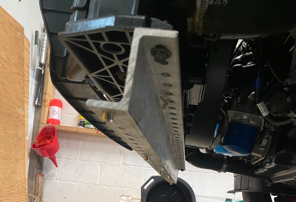
Mok Racing sells a nice oil cooler kit from Color Fittings that mounts to the front bumper beam. The oil lines are the correct length and it’s an easy install. I bought one and had it on my first engine, but it’s currently off the car, as it needs cleaning out from when my engine blew up and put metal inside the cooler and lines. I’ll likely put this on again, but it depends on how the other things work out.
On Miatas, we typically install a thicker aluminum radiator. SXTH sells one for the DCT, and I’m not sure why it wouldn’t fit the manual, but it’s specifically listed for the DCT. But before I go bigger, I’ll improve what’s already there.
Better fluids
The first thing any track car should do is dump the 50/50 antifreeze in the radiator and replace it with distilled water. For one, antifreeze is slippery, and if you lose coolant on track you’ll create a dangerous slick that may cause an accident behind you. For this reason, racing organizations ban the use of antifreeze, and many tracks will charge you for cleanup if you dump coolant on the track.
I was at a SCDA event at Watkins Glen when a McLaren dumped its coolant between T10 and T11. The first two cars through were my buddies Steve and Gregg, and somehow they saved it, but the next four cars all hit the Armco in T11 at high speed. I watched that entire incident unfold, and the cars would have taken a lot less damage, or maybe none at all, if the McLaren had used straight water instead of antifreeze.
The other reason to replace the antifreeze is that it reduces the cooling effectiveness of water. Motortrend found that compared to plain water, 50/50 ethylene glycol antifreeze decreases cooling efficiency by about 17% at 200F. If you use propylene glycol for coolant, it’s even worse.
Switching to pure distilled water will improve cooling, but you can also add products like Engine Ice or Water Wetter to improve cooling even further. I wouldn’t use Engine Ice, as it’s slippery, just like antifreeze. But both products have good documentation and user reviews that show around a 10-degree drop in coolant temperature. Just remember to go back to 50/50 antifreeze in the offseason, if there’s any chance of freezing temperatures.
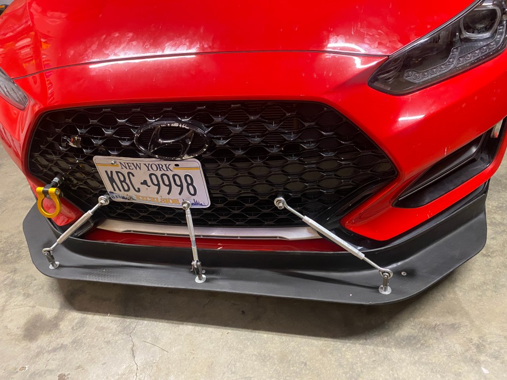
Improve airflow
With the fluids taken care of, let’s take a look at the path air takes through the radiator. The entry is large, with the bumper (and license plate) splitting the radiator into upper and lower halves. That’s OK, as a radiator typically needs only 1/3 of its total area for both the entry and exit.
Look behind the radiator and you’ll notice that the radiator doesn’t have a prescribed exit. Air has to work its way around the various components in the densely packed engine bay, before eventually exiting under the car. This isn’t an efficient way to remove air.
In addition, dumping air under the car creates drag and lift, which is bad for performance. If your car has a splitter, then air from the engine bay can wrap around the splitter, and the splitter loses suction as a result. This is a lose, lose situation.
A better arrangement is to duct the exit of the radiator. Hucho wrote about this in The Aerodynamics of Road Vehicles and provided values for both drag and cooling.
A) is the current arrangement, C) has good cooling efficiency, the least drag, and also makes a bit of downforce. Image from Hucho.
Of the arrangements Hucho experimented with, sending air upwards through an extractor vent is the easiest to manage, architecturally. The other designs require lots of duct work, or possibly a full redesign of the cooling system.
An extractor vent is also the best arrangement for drag reduction, resulting in .015 less drag. Hucho doesn’t include values for front-end lift, but as air moves upward, it pushes the car downward, and so the extractor vent will create a small amount of downforce as well.
Finally, the extractor vent is very good for cooling. The air on the front half of the hood is low pressure, and so a duct here will suck the air upward out of the engine bay, and cooling efficiency is greatly improved. I’ll take an incremental improvement in cooling with a reduction of drag and lift and call that a win-win-win.
Extractor hood
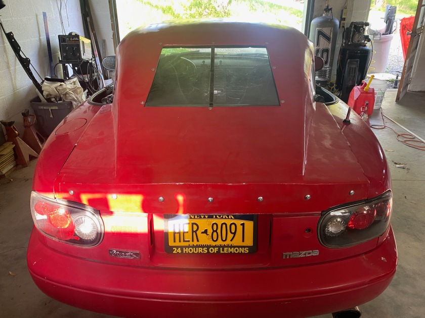
Now that I know which path to take (or more accurately, which path for the air to take), I can go about modifying my car. I didn’t want to cut vents into my pristine OEM hood, so I looked for a junkyard replacement.
Unfortunately the Veloster is rather rare, rather new, and hard to find at the breaker. Did you know they only sold 1500 VNs in the final year? Crazy that nobody wanted it, I had to get one shipped from Utah myself. Anyway, I didn’t find many hoods, and those I found were the wrong color and expensive to ship. Adding the shipping and painting and the price of Race Louvers put the whole project well over $2000. Hell, at that price I may as well buy a fiberglass hood with vents already in it.
So that’s what I did. I found a Duraflex (FRP) hood on “Summer Sale” for $650, and with shipping it was $820. There were a couple different models available with vents already in it, one with a horizontal extractor vent and one with a pair of vents on the side.
Extractor vent is too small, but it’s in the right place, directly behind the radiator.
Hood vents need to be as far forward as possible, and directly behind the radiator exit. The curvature of the hood creates a low pressure region, and so vents placed forward on the hood suck air out and upwards, greatly increasing cooling effectiveness.
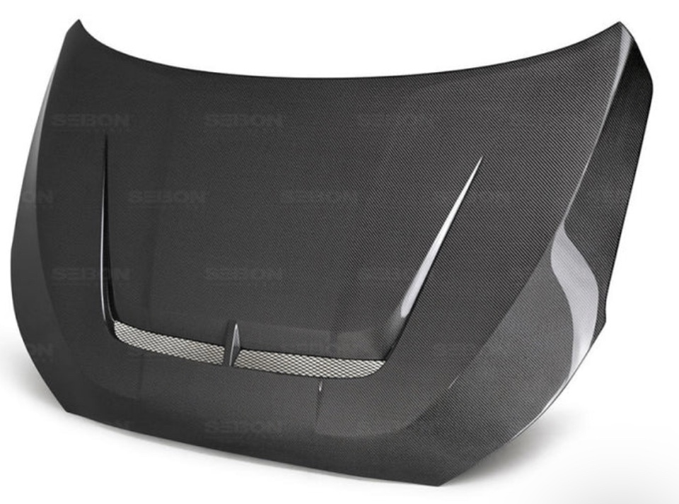
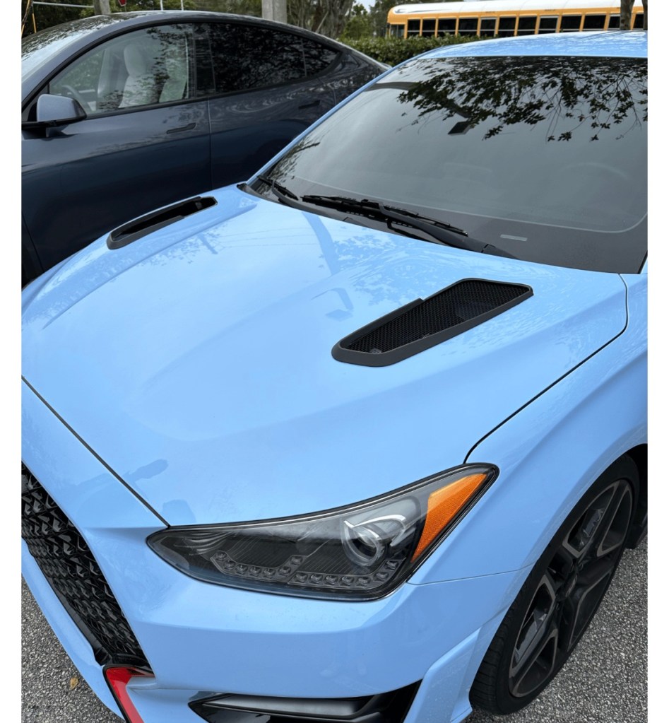
Hood vents that are placed on the side of the hood might look cool, but they don’t cool. Since they don’t send as much hot air upwards, they also don’t create as much front downforce.
The vents are placed forward enough, but won’t do much cooling because the radiator is between those vents.
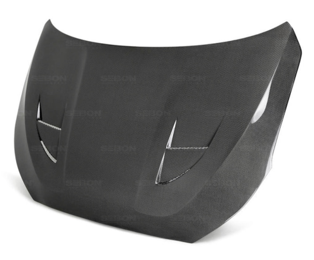
I saw a picture of one person who took a bad idea and made it worse. They took side vents and put them as far rearward as they could go. There’s less curvature on the hood here, and thus less extraction.
The absolute worst place to put hood vents. People who don’t understand how air moves around a car should not be designing and selling aero parts!
Worse yet, the base of the windshield is a high pressure zone, meaning if your hood vents extend this far rearward, air goes into the hood, not out of it. You see the same mistake with people who put vents at the base of the rear window thinking it extracts air, when it just puts exhaust fumes inside the car. Gaaaah!!!
Vents on the front of the hood send aid upward, helping cooling and adding downforce. Vents near the windshield have the opposite effect.
Good lord, I went off on a rant there. Anyway, I ordered the hood with the extractor vent. It took a couple weeks to arrive, and on unboxing, it looked pretty good. The packaging was done well, including two pieces of wood bolted to where the hinges go, to keep from damaging the pointy rear section. As I removed the bolts I found that one of them was cross threaded into the hood. C’mon people, if you’re going to put this much effort into creating a decent product, don’t have your shop monkey install the bolts with power tools!
Initial fitting.
Initial fitting was easy, just four bolts and no spray nozzles to mess with. The hood leaves some gaps on the side, and rides a bit higher in the rear, and I would have liked a better fit. There was also no hole for the hood prop, but that’s an easy fix with a big drill bit.
A more involved fix was fiberglassing the seams on the inside of the hood. These seams weren’t glued together very well, and resulted in a loss of structural integrity. I could see the hood vibrating on the highway and it raised up significantly in the wind tunnel. After glassing the inside seam all the way around, the hood was much more solid and no longer flexed. But I may add a couple hood pins just to be on the safe side.
The Duraflex hood weighs 20 pounds, which is 13 pounds lighter than the steel hood. Removing weight from the already front-heavy car is a nice side benefit, but the reason I bought the hood was for the extractor vent. It measures 27” x 1.75” or about 47 square inches, which is too small.
As stated earlier, the rule of thumb is the radiator intake and exit ducts should be about 1/3 the area of the radiator. The rad measures 25.5” x 11.75” or about 300 square inches. So I need at least 100 square inches of exit venting. However, the intake area measures about 185 square inches, and so ideally I’d like that much on the exit, as well.
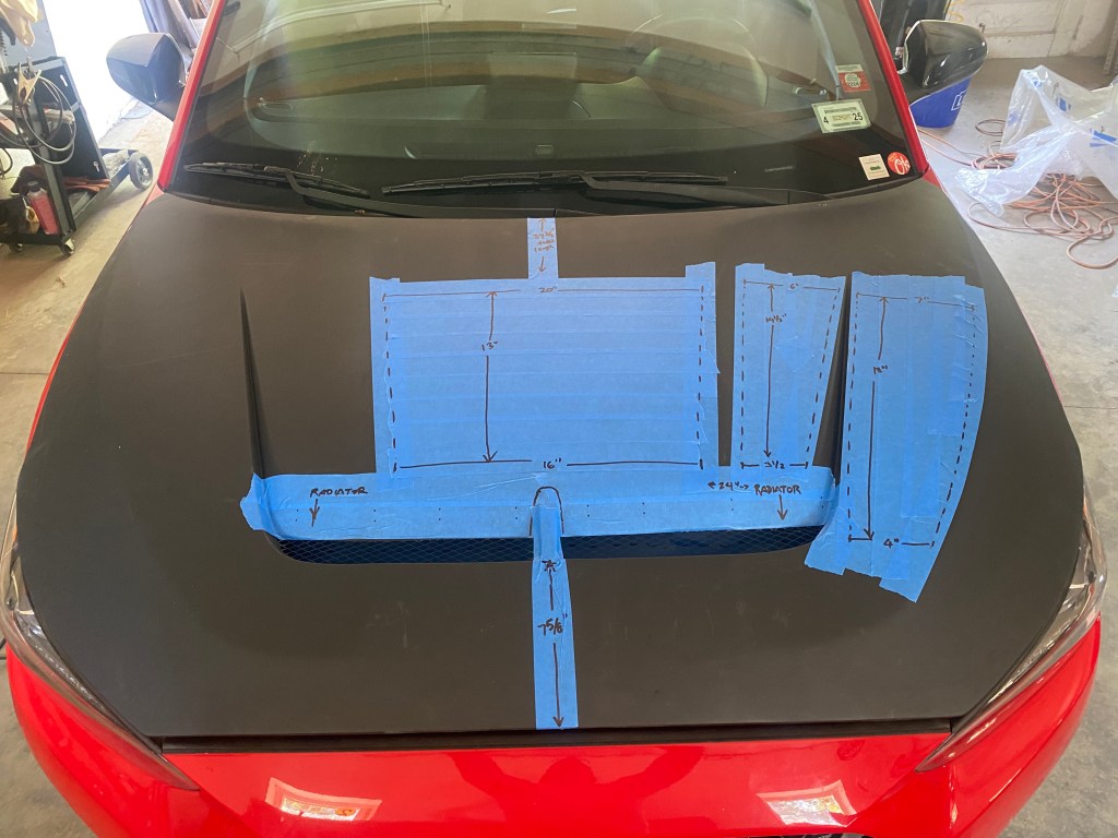
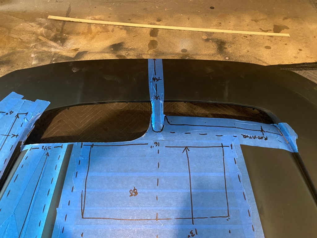
To find out where I could install more vents, I put blue tape on the hood, avoiding the contour lines and using only the flat spots. Essentially there’s one large area behind the extractor and then two narrow spots on each side.
Flat areas where vents can be added.
With these dimensions and pictures, I contacted Race Louvers. Al said they’d like to see 400-500 square inches of hood vents. Three vents would cost $850, which is more than I paid for the hood itself. Yeesh.
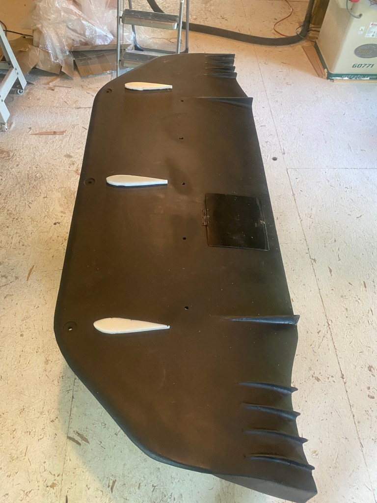
What 500 square inches looks like.
Money aside, that’s a lot of hood vents for a 300 square inch radiator. I used more blue tape to see where the ducts would line up in the engine compartment. Most of the engine is covered by plastic covers, which is perhaps why such a huge vent is necessary. Also apparent was that adding the side vents would put a vent directly on top of the intake area, which might not work well for a cold-air intake, depending on its routing.
Most of the engine bay is plastic covers, except for the slot behind the radiator where the extractor vent is located. Vents in any other area will be much less useful.
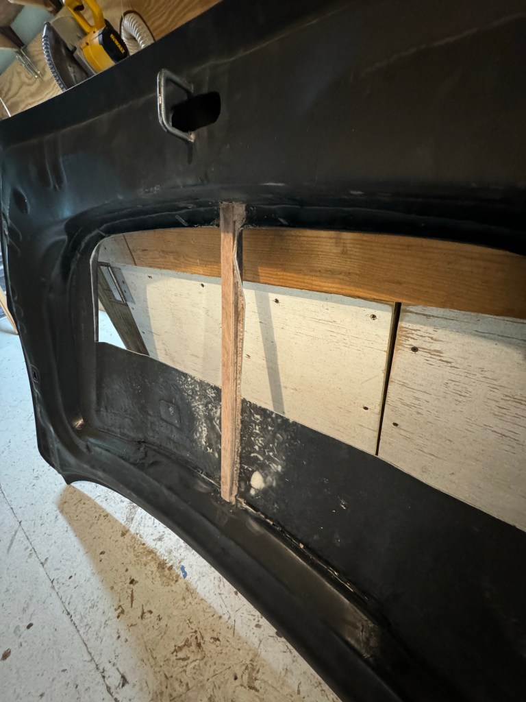
In the end I decided to take the easiest course of action and increase the size of the extractor vent, bringing the rear edge about flush with the main plastic cover in the engine compartment. I kept the support webbing in the middle of the vent and blended it into a curve which almost has a BMW look about it.
One side cut, it’s a lot larger. There’s no going back now!
Opening up the vent added 88 square inches (187% more area), and so there’s about 135 square inches of exit vents, which isn’t ideal, but it’s 135 square inches more than the OEM hood!
I also added a small wicker along the leading edge. This will build local pressure on top, as well as locate a higher stagnation point in the rear. Combined, this aids upward extraction and creates more downforce. I also made a vent cover for when I park the car in the driveway, and so that I can A/B test the difference between a vented and non-vented hood. For science.
Track test results
On track at Watkins Glen, I saw 275.9 degrees using 50/50 coolant and no hood vents. The next day I drained the coolant and used distilled water with Water Wetter, and saw 263.8 degrees. That’s not bad for a simple change like that.
With the hood vent open, the temperature fluctuated between 255.3 and 263.8 degrees, but was mostly at the higher number. Huh, so the vents didn’t cool the car much, or at least that doesn’t show up in oil temp.
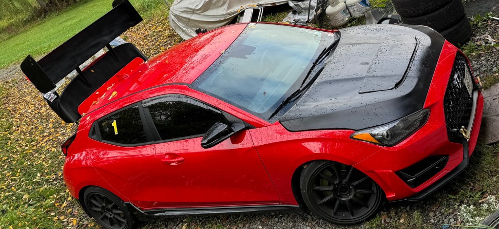
Hood with vent cover taped on. Blue taped didn’t hold well, ended up using duct tape.
At the end of the session, I turned the car off and held my hand above the hood. I could feel hot air being pumped out of the vent by the fan, and it was pretty obvious the vent was quite useful for the radiator, even in the parking lot. No need to open the hood, that’s for sure.
Wind tunnel results
I was able to test the hood vents open vs closed in a wind tunnel, effectively testing the difference between an OEM hood and a properly vented extractor hood. On a stock bodied car (no aero), the hood vents added a small amount of drag (cD .003). This makes sense, as the vents would be bad for laminar flow across the hood. The hood vents increased front downforce by 2.5 lbs and surprisingly added 4.5 lbs of rear downforce on the OEM spoiler (at 100 mph).
However, on the same car with a splitter and wing, the hood vents were more beneficial. Drag decreased instead of increased, but only by .001. More significantly, front downforce increased by .020. An easier way to visualize that is a gain of 11.4 lbs of downforce at 100 mph. The reason for that is largely because the splitter works better when air goes up and out of the hood, rather than down and under the car.
Hood vents often result in a loss of rear downforce, first because anything that pushes one end of the car raises the other, and second because turbulent air going over the top of the car reduces the effectiveness of a rear wing. However, these hood vents only lost 0.3 lbs of rear downforce on the rear wing, which is rather surprising given that there are no louvers to straighten out airflow, just a big gaping hole.
Altogether, the hood vents on the car with aero (splitter and wing) resulted in a 4.5% improvement in overall aero efficiency. I ran a simulation at Watkins Glen, and the hood vents resulted in a .11 second reduction in lap time. That’s a tiny amount over one lap, but in a 20 lap race that’s over two seconds.
Conclusion
I guess the biggest question is, would I do the same thing again? I put a few hours of labor into fixing the hood, and it still needs to be painted red. If I had found a OEM hood in the right color, and got custom Race Louvers, I’d probably be out the same amount of money for less labor, and be overall more satisfied with the result.
On the other hand, the 13 pound weight savings is a small benefit, and the black hood is kinda growing on me, even if I’m a little too mature for that look.
I’d like more front downforce, but that’s just a matter of increasing the size of the vent and adding some louvers to build more local pressure on top of them. I’d also like better heat extraction, but I’m not going to do the necessary surgery to tilt the radiator forward, or remove the fans. But maybe I can create a better exit by ducting with aluminum flashing.
I guess I’m not done experimenting with this, which is why I bought the hood in the first place. So, yeah, I’d buy it again just to do the experiments. For science.
Update Aug 2024
I increased the size of the hood vent to about 10”, which should be around 305 square inches of area, which is 650% more than the hood came with initially, and over 225% of the size it was when I modified it.
That’s a proper sized hood vent!
To make sure it was sturdy, I laminated marine plywood strips into the center support.
Underside of the hood showing the center support.
It’s very sturdy; I can put my weight on it, and it barely flexes.
Center support doing its job.
The next step is to make a cover for it, because I don’t want to collect rain, leaves, and bird droppings in my engine bay. A rain cover will also allow me to do A/B testing and see how much this helps cooling, and when I get back down to the wind tunnel, I can see the effect on drag and lift.
Rain cover in place. Per the usual, made from an aluminum street sign.
I haven’t decided if I’ll add louvers yet or not. For one, they make the rain cover more difficult to build, since louvers typically sit up above the surface. Also, according to the JKF Aero course I took, the louvers mostly benefit rear aero, and so if I want the most cooling and front downforce, I should just leave a big hole and put a 1” Gurney flap in front of it.
When I’m satisfied with how it works, I’ll probably paint it red to match the car, or a lighter color to reflect heat.
Updated 8/2023 to add Benzing wings and correct an assumption about the Douglas LA203A from Wingmen Aerodynamics.
Airfoil Tools is an amazing website, and was once the primary way I researched wings. When I look at wings, the most important factor to me is the coefficient of lift (Cl); I’m only interested in airfoils that have a Cl 1.5 or higher.
I also look at the efficiency of the wing, which is the coefficient of lift divided by the coefficient of drag (Cl/Cd). Wing efficiency is less important than downforce, because the only thing that matters is the efficiency of the vehicle, and that is typically achieved by using a wing with the greatest downforce. Even if wing efficiency isn’t that important, I wouldn’t use a really draggy wing, so I look for a Cl/Cd of 100 or higher.
So, lift should be at least 1.5, and efficiency should be at least 100. Those are nice round numbers, and easy to remember. I look at these two values at a Reynolds number (Re) of 500,000, because that represents a normal-sized wing at a realistic car speed. For a 9″ wing, 500k Re is 73 mph. For low speeds (or small wings) I’ll look at Re 200k, and for huge wings or really fast speeds, I’ll look at 1 million. But there’s really no reason to look outside of the 200k-1M Reynolds numbers and 500k is a happy medium.
I also set the turbulence value to Ncrit=5 because Airfoil Tools doesn’t allow me to set it any lower (in some cases there’s data for lower Ncrit numbers, but it’s rare.) The default setting in Airfoil Tools is Ncrit=9, and that replicates what the wing would experience in a wind tunnel, and doesn’t represent the turbulent nature of air flowing over a car, nor what’s happening in a race, behind other cars, with cross winds, open windows, and other factors.
The next important factor I look at is how the wing deals with stalling at high angles of attack. I look at this for two reasons. 1) Most cars will go faster with the wing set to maximum downforce rather than maximum efficiency, and 2) car roofs are often cambered and this means air hits the wing at different angles across its length.
For example, on my Miata, if I mount the wing at roof height, the ends of the wing are at 0 degrees, but the angle changes from -5 to -7 degrees along the roofline. If I mount the wing closer to the trunk, that angle increases to nearly 15 degrees. You can read about that and see a video Visualizing Airflow.
Given that air hits a wing at different angles of attack across the wing, at some point along its length, a wing may be stalling. When wings stall, they lose downforce and gain drag. Some wings do this gracefully, with a very gradual falloff in downforce, and others stall dramatically, with downforce crashing and drag spiking way up.
An obvious way around this is to use a wing with a 3D profile, so that air hits the wing at the same angle across the entire wing. You can read about that in my article on 3D wings.
Airfoil Comparisons
Now that you know my criteria for looking at wings, in the rest of this post I examine different wing profiles and give my thoughts on them. I’ve ordered these by Cl, which is how much downforce they make, At the end of this post I’ve included a table with summary values and some parting thoughts.
With all of that front matter and grey matter out of the way, let’s check out some wings!
Clark Y
The Clark Y airfoil (airfoil tools, wikipedia) is distinguished by a flat bottom, or when used upside down on a car, a flat top. Most wings are cambered on both sides, but the flat surface can make it easier to manufacture, and for an airplane, it’s good for training because it has gentle stall characteristics. But as a car wing, the flat top means more drag and less downforce than a wing with a cambered topside. As such, the Clark Y doesn’t quite meet my downforce threshold of 1.5 Cl at 500k, and the efficiency (Cl/Cd) is below 100 as well. Personally, I wouldn’t use this wing, but it would be easy to build.
Clark Y flat top.
NACA 6412
MacBeath often cites the NACA profiles as examples in his books, and for good reason, they are easy to understand. The first number in 6412 means percent of camber relative to chord (6%), the second number is where the camber occurs (4 means 40% of the chord), and the third number is thickness (12%). NACA 6412 meets my criteria for a good car wing with a Cl over 1.5 and a Cl/Cd over 100.
NACA 6412 looks good.
I like NACA profiles for another reason: they allow me to change the variables and see what happens to lift, drag, and efficiency at different Reynolds numbers and angles of attack. For example, I’ve read that maximum lift on single-element wings occurs at 12% thickness, and after experimenting with different NACA profiles that are identical in other respects, I know this to be true.
You can also use the NACA 4-digit generator to create your own wing profiles. For example, this is a NACA 9512. I’ve maxed the camber allowed in the tool (9.5%), set the camber further rearward (50%) to increase lift, and used the max lift thickness of 12%. I’m certain this would be a good car wing.
NACA 9512 looks great.
Cambered Plates
Probably the easiest way to make a wing is to cut a metal pipe lengthwise into strips, and then lay two of the curved pieces on top of each other. Put a semi-circular nose on it and weld the three pieces together. This is a cheap and easy way to make blades for small wind turbines, I don’t see why you couldn’t do the same for a car wing. It’s so DIY I want to make one for 24 Hours of Lemons.
The simplest of wings, two cambered plates connected together.
You can make these wings in different thicknesses, and at 12%, it has a high Cl of 1.7. However, this wing has a lot of drag and so the efficiency is quite miserable, less than half of my threshold value of 100. Still, for a low-speed wing where drag is inconsequential (autocross), this would totally work. And for 24 Hours of Lemons, it’s better than a snowboard, skateboard, angled plywood, etc.
LNV109A – NASCAR COT Wing
NASCAR flirted briefly with car wings, but after 93 races went back to spoilers.
The airfoil they chose was the Douglas/Liebeck LNV109A high lift airfoil. I don’t know what decisions went into that choice, but the numbers don’t excite me. I mean, it would be cool to have one for historical reasons, but I’m not actively searching eBay for one.
If you look at the Cl vs Alpha chart (which you can think of as how much downforce the wing makes at different angles of attack), you can see the wing has a max Cl of 1.7. Downforce peaks at 12 degrees and then falls off drastically. Compare this to the Clark Y above to see what I mean.
Next, take a look at the efficiency of the wing. Most wings have a bell-shaped curve with maximum efficiency in the middle of the range (say 5 degrees). What’s interesting here is that max efficiency occurs at 10 degrees, with a Cl/Cd is 117. Maybe that’s why NASCAR chose this airfoil shape? If you want a wing that creates close racing at high speed, this would be a good choice. But if your agenda is low lap times, I think there are better choices.
FX 72-MS-150A
I have three different made-in-China wings, one came as a double wing, the other two are single wings. They are fun for experimenting with, cheap, and disposable. Whoever designed them chose a similar profile for all of them, which is akin to the Wortmann FX 72-MS-150A.
Made in China wings.
Some of these wings are sold as “universal” and so they are flat on the bottom with two mounting rails underneath. I modify these by adding wood to the bottom and rounding it.
MIC wing modified.
By the numbers, this is a decent airfoil for a car, it makes a lot of lift (1.8) and is very efficient (121). The only drawback is when this wing stalls, it falls out of the sky. This isn’t a wing that you want to set for maximum downforce. Make sure you take into account the downwash angle on the roof.
Douglas LA203A – Wingmen Aerodynamics
Wingmen Aerodynamics makes a wing based on this profile. I originally thought it was a Clark Y, but was corrected in the comments section. I’ve seen this wing at a couple different races, and I was immediately impressed with the build quality. It looks very light and feels stiff and strong.
Wingmen Aerodynamics. Sweet.
With a max thickness of 15.7%, the wing is on the thicker side, but oddly, it also has less topside camber than most motorsports wings. At around 1.75 Cl, the LA203A, doesn’t make the most downforce, but it’s the second most efficient wing in this article. It also has a very gentle stall characteristic, and should work well behind a cambered roof line, or lower on the trunk lid where the center and ends of the wing are at very different angles of attack. Nice choice, Wingmen.
Very efficient.
GOE 464
This is a very thin airfoil, almost potato chip in profile. The only reason I find this aIrfoil interesting is because APR makes a carbon fiber wing using a similar profile. APR’s GTC-300 wing has more camber, but the GOE 464 is close enough to look at some numbers.
Potato chip profile.
The GOE 464 has a max Cl of 1.85, which is a lot of downforce, and the efficiency at 500k almost reaches 100. It’s an interesting wing, but the numbers aren’t blowing me away. Also, it’s so thin that it would be difficult for me to build and make rigid enough, and I feel there are better choices.
GTC-300 is not unlike GOE 464
Better airfoils
The previous airfoils were all interesting in one way or another, and some can be bought or made pretty cheaply. But all of the following airfoils have superior numbers, and I feel would be better choices for a car wing. Choosing between them is difficult, as there’s always a trade off between lift, drag, and stall. Each airfoil has a niche where it outperforms the others, and I’d be happy with any of them.
Church Hollinger CH10
Any wing that makes around Cl 2.0 is in the category of ultra high lift. The most efficient of these is the Church Hollinger CH10. At 500k, this wing has a Cl/Cd of 132, which blows away the others.
Get thee to church. Church Hollinger, that is.
If you look at the data, peak downforce is around 10 degrees. Max efficiency (Cl/Cd) occurs at around 3 degrees, which is where I’d set the wing on a Miata. This would put the angle of attack at 8-10 degrees over the roof, and 3 degrees at the wing ends. Perfect.
I believe that the Wing Logic extruded aluminum wing is a CH10, and if you think it looks a lot like the 9 Lives Racing wing, it’s because they are close cousins in shape. Both airfoils have their maximum thickness at 30% of chord, and their max camber at 50% of chord (measured from the nose of the wing). The difference between them is the 9LR wing has two degrees more camber and 2% more thickness.
GOE 652
The first thing you notice about this wing is the thickness of the leading edge. It carries that thickness over much of the wing, and the 17% chord thickness is unusually phat. The purpose of that (I think) is to keep air attached at steep angles of attack.
She thicc.
The 652 has a very gradual stall, and should tolerate being set at too steep of an angle. For this reason, I believe this wing would be a good for a car with a highly cambered roofline, or where you have to mount the wing closer to the trunk. In both cases, there are large changes in apparent wind angle across the wing, and this wing won’t care as much as other wings.
This isn’t a particularly efficient wing, and even though it exceeds my threshold value of 100, it does that at a very low angle of attack. However, the high lift of Cl 2.0 puts this wing into elite company. I’d wager this would make a good upper element for a dual-element wing, not just the because of the shape, but because the added thickness would make it stiffer in a smaller chord. I’m definitely making one of these someday.
Eppler 420
The Eppler 420 isn’t as efficient as the CH10, but has slightly more downforce and a gradual stall. It’s a good all-purpose shape, and because it’s thicker, would be a strong contender for either element in a dual-element wing. As an all-purpose wing, it’s hard to choose between the CH10 and E420. The former is more efficient, the latter makes more downforce.
Eppler 420 is a solid all-around choice.
It’s also a pretty good wing for low Reynolds (low speed or small wing). The Porsche Cayman R has a tiny rear wing, and it’s probably not a coincidence that the profile looks a lot like the Eppler 420.
Porshe Cayman R wing looks like an Eppler 420 at 5 degrees.
Wortmann FX 74-CL5-140
This airfoil wasn’t on my radar, but in writing this article I looked at every airfoil on the Airfoil Tools site. Glad I did, this one is a keeper! With a Cl that’s nearly the same as the Selig wings, and an efficiency closer to the CH10, this wing sits in rarefied air.
It’s nice, I like.
You don’t get something for nothing, and the tradeoff is a steep drop when it stalls. If you want to go after maximum lift with this airfoil, mount it high where the angle of wind doesn’t change much. I’m not sure what’s happening around zero degrees, but I wouldn’t set it there anyway.
I have more to say about this wing after reviewing the next wings. I’m tempted to build one, so stay tuned on that.
Selig 1223 and 1223 RTL
The Selig 1223 and the Selig 1223 RTL are Downforce Royalty. The RTL version is slightly thicker, which results in higher lift and drag. The RTL can be set to 15+ degrees and approaches a Cl of 2.5. That’s huge.
Selig 1223 (red) and 1223 RTL (green).
Both airfoils make a lot of downforce, but also a lot of drag, and their Cl/Cd efficiency is less than 100 at all angles. Ergo, I would use this airfoil for low speed or for a car with a lot of power. Those are also usecases for a dual element wing, which might be a better choice if your racing rules allow that.
AeroDesign wing from Australia appears to be Selig-ish.
Let’s compare the two Selig wings to the FX74. These graphs are from Re 1M because I plan to use these for a larger chord wing. In the comparisons you can see how the S1223 wings are clear winners in downforce, but the FX74 is far more efficient at Cl 2.25 and below. I’ve drawn a blue dashed line at 2.25 Cl, and you can see that the FX74 has a sweet spot where’s it’s making a lot of downforce without much drag.
Re 1M, Ncrit=5
This is how five of the airfoils stack up at 500k Re. I didn’t include the RTL because that’s in the previous charts. I’ve pointed out a few areas that differentiate one wing from another.
How the players stack up at 500k Re.
Motorsports wings
All of the previous airfoils are aviation wings that have been adapted to motorsports use. Cars don’t (or shouldn’t) fly, and they have much lower Reynolds numbers, and so it makes sense that car-specific wings would be shaped differently.
Indeed, Enrico Benzing did a bunch of research and came up with a lot of different designs specifically for motorsports use. None of these would be particularly good at flying, but they are better choices on cars.
Similar to the NACA wings, the Be-series of numbers tell you about the shape:
The first two digits are the thickness of the wing, relative to the chord. Aviation wings make maximum downforce around 12% thickness, but cars wings are often thicker.
The next number is the location of the thickness. Many of Benzings wings have the maximum thickness at 20-30% of the chord. This is supposed to add more downforce.
The first two numbers after the dash are how much camber the wing has. If you use the Airfoil Tools NACA generator to make your own airfoil shapes, you can’t enter anything higher than 9.5%, and Benzing’s wings are all more than that.
The final number is the position of the maximum camber, in tenths. More rearward camber generally means more downforce.
Be 183-176 – TCR Wing
As I stated in the NACA wing details, downforce typically increases as you increase thickness, up to about 12%, at which point that trend reverses. But that’s not true for motorsports wings, but even so, this is a very thick wing, the chubbiest in the Be series. This is also extreme camber, I haven’t seen an airfoil with this much.
The TCR regulations state this wing must be 1380mm x 250mm (54.3″ x 9.8″) and you’re not allowed to use a Gurney flap. From the wind tunnel testing I’ve done, I can tell you that a wicker would absolutely help this wing, maybe to the point where it works.
Make your own wing using these coordinates.
Knowing what I know about wings, I wouldn’t use this one unless I was forced to. Unfortunately, like the LNV109A was with NASCAR, this wing is a homologated part, and all the TCR cars are forced to use it. Worse still, you need to mount it (including brackets and endplates) below the roofline. On a hatchback.
My buddy Josh and I inspected one of the hatchbacks at a wet Grid Life race, and the water left streaks that were like flow-vis paint. You could clearly see where the air was separating on the back third the wing. In my opinion, this airfoil is too thick, it has too much camber, and air can’t stay attached along the entire surface, causing a loss of downforce and increased drag. I could be totally wrong about the TCR wing, and may have to eat my words. One day I’ll test one in a wind tunnel to be sure.
I wrote some additional comments about this wing in my Grid Life recap, and I’ll copy the most salient one here. “Leave it to the people that fucked our asses with diesel-gate to bugger a racing series with a wing that stinks of shit.”
Be 123-125 – 9 Lives Racing Big Wang
Probably the most popular motorsports wing is the 9 Lives “Big Wang”. The shape is essentially a Be 123-125, but with a modification to the rear geometry to support a Gurney flap. The shape is conservative compared to other Benzing wings, and measures in with numbers closer to aviation wings. Never mind that, because it’s a fantastic motorsports wing.
Big Wang with Gurney flap slot cut off for experimentation with chord.
In my wind tunnel testing the Big Wang was second best to the MSHD, and outperformed my S1223. This surprised me considering the amount of research I’d read on low-Reynolds high-lift airfoils; I predicted the S1223 would be a clear winner. Nostradamus I ain’t.
In a research paper on multi-element wings, this shape (or rather a very close cousin of this shape, the 122-125 with thickness 10% further forward) was the best performing main element. So if you are looking at a dual-element wing, this is the best off-the-shelf choice. Or even if you’re looking for a single element wing, it’s pretty hard to beat this on performance.
Be 183-155 – Procar Innvoations
Procar Innovations makes a wing that looks like the TCR, but it has less chord and is less extreme. I measure it up at 183-155, meaning it’s just as thick as the TCR wing, but it has less camber and the location of the camber is 10% further forward.
PCI makes a fine wing.
I tested this wing in the wind tunnel and it was really good, on par with the 9 Lives Racing wing. The end plates fasten with two 8mm bolts instead of four 5mm bolts, and could easily support a double element. The PCI wing doesn’t have a slot for a Gurney flap, but I would rivet on a wicker. My wind tunnel testing confirms that wings with a lot of camber really like a wicker, and this one gained 165% downforce with a 1/2″ piece of angle aluminum taped on top.
MSHD
I didn’t know about this airfoil until recently, as it doesn’t show up in Airfoil Tools, Bigfoil, Enrico Benzing’s Wings, or any other text I own. Because of that, I can’t display the same charts, but I can describe some of the advantages.
There’s a scientific paper on this airfoil making a direct comparison to the S1223 for use in low-speed motorsports applications. The main advantages of the MSHD over the S1223 is an even higher Cl value, softer stall characteristics, and a large range of AoA. To my present knowledge, this airfoil makes the most downforce of any wing listed here. If the Selig wings are the royalty in a deck of cars, then the MSHD is the ace of spades.
Familiar S1223NKOTB MSHD
Shape-wise, the airfoils are not that much different, but the MSHD has more camber. It almost looks like someone took the S1223 and kept pushing the middle downward until they got flow separation. To plot the wing you can use the values in the spreadsheet.
In my wind tunnel testing this wing produced the best numbers. It also did very well with a Gurney flap. It was fairly easy to build in foam and fiberglas, and I did a DIY writeup on that in another article, but it was hard to get the exact shape because of the thickness of the fiberglass.
Update: An aluminum extruded MSHD is now available from Wing Logic. See my article here. This is the wing to get!
Summary Data
Here are all the wings sorted by cL. For each wing, I’ve also listed the max efficiency, and the angle where that occurs. Note that the fastest way around the track is often right around max downforce, not max efficiency. But efficiency is somehow important for marketing, even if that doesn’t really matter.
This article is theoretical in nature, and lacks real-world testing results. Back when I wrote this article, I hadn’t done any wind tunnel testing. Since that time, I’ve tested many different wings in the wind tunnel, and the results have been… unexpected. For example, I’ve tested the exact same wing on three different cars and have had lift/drag ratios that range from around 3.5:1 to 25:1. So there’s obviously a lot going on here other than just the shape of the airfoil.
The wings tests span two wind tunnel reports, because a Miata and a Veloster N are quite different. Click the button, fill out the form, and you’ll get a link where you can download the reports.
The Veloseter N undertray does a good job of covering the mechanical bits that cause drag under the car. It doesn’t have diffusers in the wheel wells (like a Porsche or Tesla), but there’s a small dam in front of each tire to reduce drag. There are holes for cooling and access, and the general design is one of convenience rather than performance.
The top-side is more fashion than function. The OEM front fascia has lots of vents, both real and fake, and some of the bodywork is angled to hold a small amount of downforce. As factory aero goes, it’s pretty decent, but there’s also a lot of room for improvement.
I’m going to make my own splitter, but before I do that, I’ll take a look at what’s available for purchase.
Aftermarket front lips
Front lips that are lower and/or longer than the OEM lip are a popular modification. They can reduce drag by reducing the amount of air going under the car, and hold a small amount of pressure on top, making some front downforce.
This lip just extends the center portion. It looks nice, but does nothing.
But if the front lip isn’t integrated into the undertray, it might increase drag due to flow separation between the lip and undertray. In general, I don’t think front lips add much performance and are largely poseur junk.
Aftermarket splitters
Functional front aero starts with a splitter. Splitters reduce drag by keeping some air from going under the car, but the real function of a splitter is to make downforce. I wrote about common splitter mistakes in Your Splitter Sucks!, and if you haven’t read that, it’s required reading.
With that in mind, I’ll review some of the splitters I’ve seen online, bash them mercilessly, and then show you something a fuckload better.
Aero Blitz splitter
The Aero Blitz splitter is half way between a front lip and a splitter. You can see it’s pretty small. There’s some surface area to hold pressure on top of the blade, but it’s not going to be a very useful amount. Anything that fastens with double-sided tape and self-tapping screws isn’t meant to make downforce.
Cosmetic junk.
The shape of the Blitz splitter follows the shape of the front fascia and gives it a “Batarang” shape. Most of the aftermarket splitters do the same, and I don’t like it. Functionally, it just doesn’t make sense. But then again, anyone buying this cares that it looks like a splitter, not that it functions as one.
Aerotekk splitter
Aerotekk has done a decent job making a product that looks great and is functional, at a reasonable price. This is a good solution for someone looking for a little bit of front downforce.
Proper shape without Batman-inspired cuts.
The mounting points look OEM, but if you read the description, it says that it doesn’t come with any brackets, and that mounting the splitter is up to you (or as they say, a professional). So is this just a flat an alumalite blade mounted flat against the undertray?
Aerotekk splitter probably works OK.
I don’t see any height adjustment, but a clever person could find a way to do that when they figure out the mounting brackets. With height adjustment you’d also need an air dam to fill the front gap.
You might also install splitter diffusers, but this would take away from the rigidity (alumalite isn’t that strong). I don’t see splitter support rods, nor what they attach to. Anyway, an OK starting point for DIY modifications.
APR splitter
The APR carbon fiber splitter is about twice the price of Aerotekk’s, has the same cutouts for the wheel deflectors, but looks to have a different mounting solution. It’s also dead flat, so it’s not doing much to create suction.
The splitter has some thickening and rounding of the front edge, but could be larger. The shape of the front lip has the bat-wing shape that follows the contour of the bodywork. Whatever.
What are those rods mounted to?
It looks like there might be some height adjustment via the splitter rods, but the mounting of said rods is sus. Do they adjust for height and if so, how much? Are they really just fastened to the plastic radiator grille? How much weight can they hold? All said, I’m skeptical this does anything more than look like a splitter.
Street Aero splitter
The Street Aero front splitter is made from 6mm alumalite, and a consequence of the material is that it has a sharp leading edge, which results in flow separation. The splitter doesn’t seem to have any height adjustment, and appears to have negative rake (pointed upwards)!
Dullards create sharp leading edges.
The shape is the bat wing I’ve come to expect out of any of these appearance-first designs, but this one has larger tire cutouts for no good reason, and there’s no oil filter access, so I guess you have to remove the splitter every time you change the oil?
Batman called, wants his hang glider back
Ventus splitter
Ventus Autoworks appears to have the same, flat, flimsy, do-nothing splitter as everyone else. I’m not sure of the construction, but it claims to have an outer layer of carbon. (Actual carbon or vinyl, it’s hard to tell.) The splitter attaches via splitter rods that are equally suspect as the APR ones.
The size and shape is reminiscent of the others, but you can also opt for winglets!
You can get the APR splitter with little vertical winglets on the end, which probably act as an air fence. The Veloster N already has air fences in the fascia, but maybe more is better.
Splitter rods look legit, but I wonder what they attach to….
I will say it looks good, and blends in with the style of the car. Even the winglets are pretty tasteful when you see the whole package. But does the splitter do anything for performance? Since it’s not much lower and there’s nothing happening underneath, it can’t be doing much.
DIY splitter
None of the aftermarket splitters do what I want, so I’ll make my own. What I’m looking for is this:
Height adjustment – Splitters make downforce via suction, which is highly dependent on height. For street driving, I want more ground clearance, but for track driving, I want it lower. I also want to be able to tune the amount of front downforce by raising and lowering the splitter. It’s just like having a wing that’s adjustable for angle.
Attached flow – Air separates on sharp edges, so the leading edge needs to be as large and rounded as possible. Trailing edges need to break cleanly.
Suction – A flat splitter doesn’t create a lot of suction. I want to accelerate the air under the splitter by expanding air behind it. This can be accomplished using splitter diffusers, but because the Veloster is so high off the ground, I’ll curve the entire undertray upwards.
Splitters gain downforce linearly as they get closer to the ground, and at around 3” the suction goes up exponentially. At about 1.5” from the ground, downforce decreases sharply. So ideally you want your splitter in that 1.5” to 3” window. But this is a street car on stock (soft) suspension, and so I can’t go that low.
Ground clearance on the VN is about 6” on the front fascia, and I can reduce that by a couple inches, but any more than that will give me problems when street driving. I used an aluminum z-plate to attach the middle of the splitter and lower it slightly.
Z-plate to lower the splitter. Note the rivnuts which protrude downwards and act as locating bosses for the splitter.
A splitter needs to be stiff enough not to deflect at speed. You don’t need to be able to stand on the lip like I see people doing, because most of the downforce is made behind the lip. I used 6mm (1/4″) Meranti plywood for most of the undertray, I added a layer of 9mm on the front. A much easier solution is to simply laminate two pieces of 1/4” together as a continuous curve.
Laminating a curve into the back of the splitter, essentially making a diffuser across the full width.
Rather than using splitter diffusers, I’ve curved the entire rear of the splitter upwards at 12 degrees. This will expand air at the rear, which accelerates the air in front, maximizing suction across the entire splitter blade.
Note that for wind tunnel testing, I tried a flat splitter, and curved splitters with 5-degree and 12-degree curves. Curvature wins, big time.
Underside pic shows two strakes that add stiffness and direct air into the wheel wells. The stakes also show how much curvature there is.
The problem is, what to do with the diffused air? A proper race car would dump the air into the wheel wells and use vents behind the tires and on top of the fenders to extract the air. I don’t (and won’t) have either of these vents, and consequently the splitter can’t make as much downforce. That’s the consequence of having a dual-duty car.
I made the curvature by scoring the plywood and filling the gaps with epoxy.
You might be wondering what happens to the air that goes under the car, since it isn’t being extracted properly. Me too. I’m guessing that the air just diffuses under the car creating more drag. (Although this splitter actually reduced drag.) But I will always trade front downforce for drag, so I’m not very concerned by this. I also don’t have a flat belly pan and rear diffuser, so I’m not concerned with keeping air attached underneath.
As a tire rolls forward, it compresses the air underneath, shooting a jet of air sideways on either side. This phenomenon is called tire squirt, and it can have downstream effects on underbody aero. The faster you go, the more pressure on the face of the tire, the faster the tire rolls, the more compression, and hence the more tire squirt.
To reduce tire squirt I’ve added strakes in front of the tires. These spin a vortex and hit the tires at and angle, sending lower energy air sideways across the face of the tire. This reduces tire squirt and aids in extraction beneath the splitter blade.
To make the strakes I cut an arc into the splitter and slid rectangular pieces of thin plywood in the slots. I then trimmed the top side (the side facing the engine), and then fiberglassed over the exposed bottom strakes.
Mocking up the location for splitter pucks.
To support the front of the splitter, and provide height adjustment, most people use splitter rods. I made my own from elevator bolts, clevis pins, and turnbuckles. The first hurdle was where to mount the splitter rods to the frame or bumper. Splitter rods that mount to the bumper plastic are poseur bullshit.
I found out that a 4” square U-bolt is a near perfect fit. You have to bend them out about 1/8”, and then they slip right around the front bumper. At first I bought 5/16 U-bolts, but then switched to 3/8”, it’s way stronger.
3/8” x 4” square U-bolts with coupler nuts on the bottom.
I placed the splitter rod supports 19.5” apart, so that they line up with a couple holes in the front grill. You’ll have to cut the webbing out to enlarge the hole. There are coupler nuts on the ends of the bottom of the U-bolt, which is where the splitter rods attach.
Use tin snips or dykes to cut the plastic webbing so that the coupler nuts can poke out.
I originally made two splitter rods, and then decided to make three. I don’t know that three is really necessary, but I tend to overbuild things.
Mocking up the splitter shape. Notice the two splitter rod supports coming out of the grill.
The splitter rods attach to the splitter using elevator bolts. Mark a hole with a small drill bit, recess the bottom facing using a Forstner bit, and then drill a hole large enough to install the elevator bolt from the bottom. This makes a nice flush fit, with lots of support from underneath.
A Forstner bit will make a nice hole so that the elevator bolt sits flush.
The elevator bolt attaches to a clevis on the top side. Make sure to match the thread pitch on both, as the elevator bolts are typically a coarse thread and the clevis joint is usually a fine pitch. You can find the coarse thread clevis from McMaster Carr and everything else from Lowe’s or whatever local hardware store you use (but avoid Home Depot for their shady business practices). Fender washers between the clevis and elevator bolt is a good finishing touch.
Clevis attaches to elevator bolt.
The splitter is adjustable for height via turnbuckles and in the lowest position sits about 2-3” lower than the front lip, and so I need to cover the gap with something. Most people use race plastic or garden edging. It doesn’t really matter what you use as long as it blocks the air from going between the top of the blade the bodywork.
The splitter is 69” wide, and for aesthetics, I made the airdam go around the bumper fascia on the sides of the car. There’s no performance gained from that, and a 67” splitter with an airdam only on the front section would have been a lot less work. I made 5-degree and flat splitters 67” wide and they worked great.
Mocking up the airdam in plywood, later this will be laminated with fiberglass.
This is a street car, and so I didn’t do a lot of the downforce-producing tricks I would have done on a track car. For example, other than the strakes under the splitter, I’m not doing anything to kick air sideways, or extract air from the wheel wells. There are no vents behind the fenders or on top of them.
The splitter rods have too much angle, and I’ve since changed the mounting points to be as wide as possible. Just the same, the splitter blade feels like a sidewalk when I stand on it.
If I was building another dual-duty splitter, I wouldn’t use the z-plate, it restricts the vertical height adjustment. Instead I’d bolt a piano hinge to the undertray. This would allow a full range of motion from stock height to resting on the floor. I’d make the splitter slightly thicker so I could use two splitter rods instead of three, and then it would be easier to adjust the height.
For a track car, I’d make a different splitter, wider, with some treatment on the ends to kick air up and sideways. And I’d make it longer, maybe 5-6”. It would be adjustable for height and I guess it could be used on the street, but would also need a lot more rear downforce to balance out.
But even as is, this is a good splitter. I tested this splitter in the A2 wind tunnel and it reduced drag while making good downforce. At 100 mph it made 165 lbs of downforce and reduced power consumption by 3.1 hp. This is good, but can be improved upon.
I’ve written in the past about aero balance, and how I like to add more rear downforce than front, so that the car can be tuned to oversteer in slow corners and push in the fastest corner, and be neutral for most other corners. But on a FWD car, that doesn’t actually mean you add twice as much rear downforce, you have to take into account the weight of the front and rear of the car. Most FWD cars have roughly 2/3 of the weight on the front tires, so adding say 220 lbs of front downforce adds 10% more front grip, but adding 220 lbs rear downforce would be 20% more rear grip.
I still need to tune the aero balance on the car, so I can’t say exactly how much rear aero is required to balance the front. But this is why wings are adjustable for angle, and why splitters should be adjustable for height and angle as well. And yet none of the manufactured splitters are adjustable for either height or angle, and why you should DIY your own.
I recently got an older AiM Smarty Cam, and it came with an AiM Solo DL and GPS-08 external antenna. There are a lot of AiM products and it’s confusing to know how to put them together, so I contacted Peter Krause who patiently walked me through what I’d need.
It’s really easy for the Veloster, or really any other car with OBD2. The 7-pin port on the Solo DL connects to the car’s OBD2 port. A 5-pin male to male cable goes between the Solo DL and the Smarty Cam’s EXT port. That’s it. Or rather, if I had any of the cables, then that would be it.
The camera’s 4-pin GPS port isn’t used in this configuration, and so I’ll be getting rid of the GPS-08 antenna, which will more than pay for the cables. These are widely available; I paid about $50 each.
In this configuration, the Smarty Cam gets power and GPS info for speed and lap timing, as well as the trigger to turn on and recharge from the Solo DL. The Solo DL in turn gets its power and extra channel information from the car’s OBD2. So essentially the car powers both devices, and you don’t need any other cables. Sweet.
I’ll also need to load the latest track maps into both devices. This means downloading the latest version of Race Studio 2 and uploading the track maps into the Solo DL. And then downloading the latest version of Race Studio 3 and uploading the track maps to the Smarty Cam. Weird, but OK.
With all that done, I should be able to get quite a lot of extra information, in addition to the GPS data I’m use to.
Extra channels I’ll get from the car’s OBD2.
I like my AiM Solo mounted on the windshield, as far left and low as I can put it. Most road courses go clockwise, and so the Solo is out of view for the majority of corners. I’m addicted to the delta timer, and this is a way to impose limits on screen time.
Tucked the wires into the gutter.
Running the wires was easy and oddly fulfilling. I pulled the rubber moulding away from the door jamb and tucked the wires into the slot below. The wires need to go in and out of this slot, so I used extant gaps in the interior panels for that. Going aft, I ran the wires back towards the seat belt anchor and popped them out under the driver’s seat and under both seat rails. The wires then go up to the camera.
I had a lot of ideas on how to mount the camera, and this is the one time Facebook read my mind and sent me the correct ad. There’s a product made specifically for cars called a Lapole, and it’s compatible with a lot of cameras, but doesn’t mention the Smarty Cam. I could probably adapt it to work, but at $100, I shouldn’t have to.
So I bought a heavy-duty adjustable spring-tension curtain rod for $20 and added a cam-lock mount with a 1/4-20 thread. This was one of those items I knew I had somewhere collecting dust, and it was going to take me 1 minute or 1 hour to find it. Thankfully just 1 minute.
Pole mount for the camera allows easy setup and height adjustment.
There’s a lot of tension on the spring-loaded pole, so I cut a piece of plywood on top to use as a clamping caul, so that I don’t ruin the headliner. I was less concerned with the floor and simply ran the pole down to the carpet.
The camera mount seems quite stable, and I’m chuffed it all came out so nicely. I’ll make some tethers next and find a better way to bring the wires up the pole, but good enough for a quick project. I haven’t taken any video yet, but I’ll update this post when I get it on track.