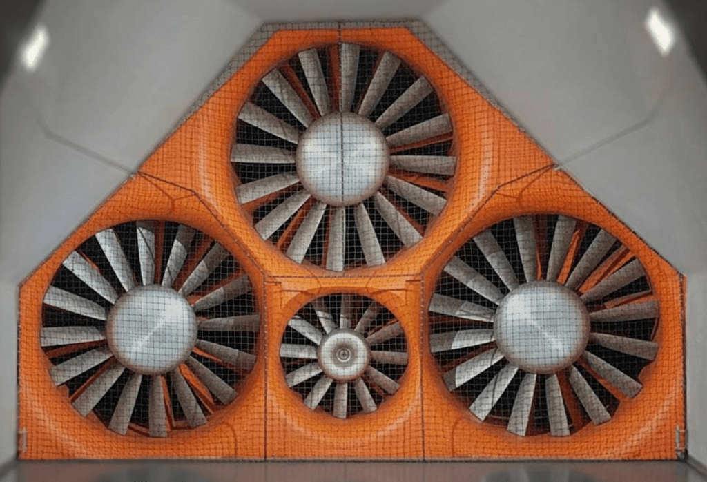
On Monday I’m going to the A2 Wind Tunnel in North Carolina. This will be my first trip to a wind tunnel, and I hope to get many questions answered. Like most things in life, I’m certain I’ll come home with twice as many questions as answers, and I’ll be making regular visits thereafter.
The tunnel is a 10-hour drive, and expensive, so I want to be well prepared for the test, with lots of parts that come on and off quickly. But for sure I’ll need a second set of hands as well.
I asked around online to see if anyone could come help me, and while I got a few tentative offers, nothing solid. Then I messaged AJ Hartman for advice on how to not fuck up, and he said he will meet me there and help with parts swapping and data analysis! No. Fucking. Way. I had to dick punch myself to see if I was dreaming. Ouch; this is for realz.
There are so many things I’d like to test, but at $600 per hour, I’m already looking at a $2400 bill! Every minute I stand around or waste time is $10, so I have to be efficient about collecting data and do all the analysis at home.
So what am I testing?
Three splitters
Because touring cars are front limited in downforce, front aero is the most important thing you can do for performance. The more downforce you can get in front, the more you can add in the rear. It’s easy to add more rear downforce using greater wing angle, a bigger wing, a Gurney flap, etc. But getting more front downforce requires a lot of work.
Splitters are the easiest way to make front downforce, and many people add a splitter beneath the factory lip, or build an air dam. Racing rules often limit the length of the splitter lip, as well as how far rearwards it can go (front axle being normal).
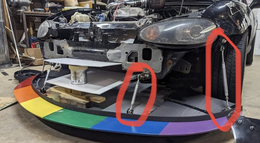
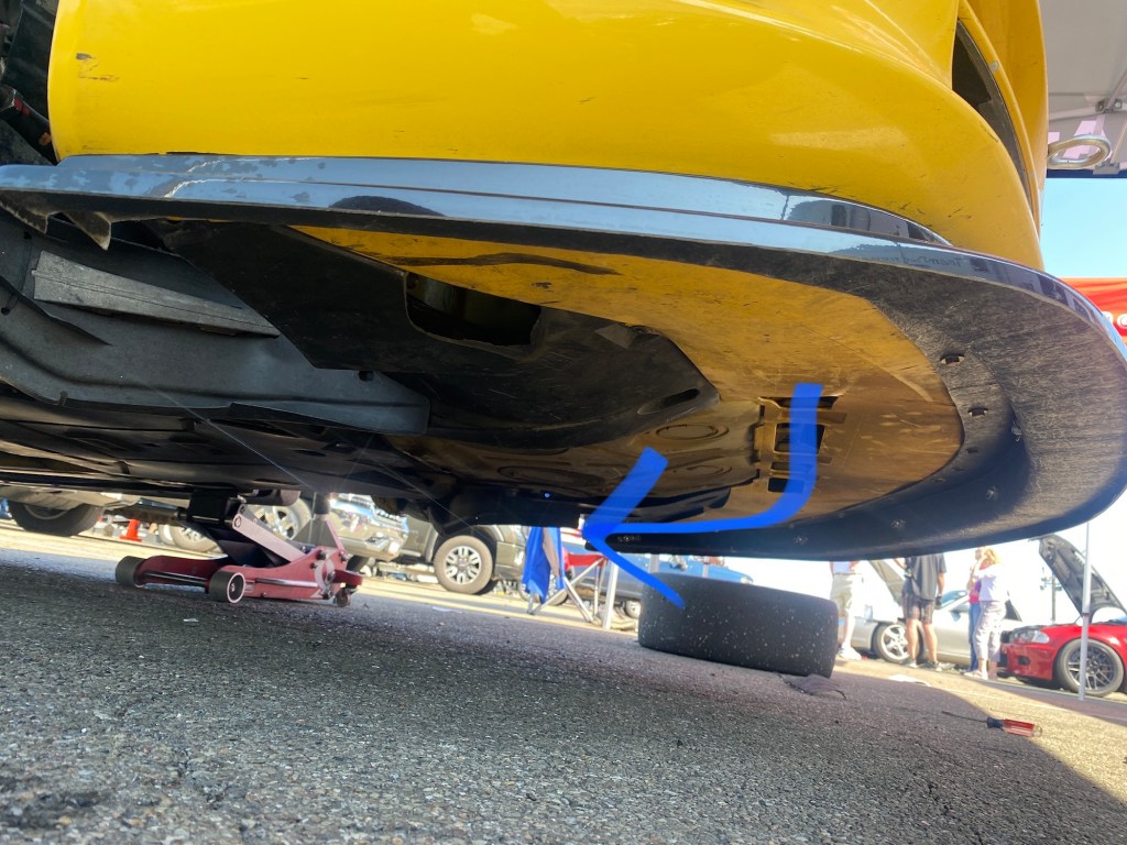
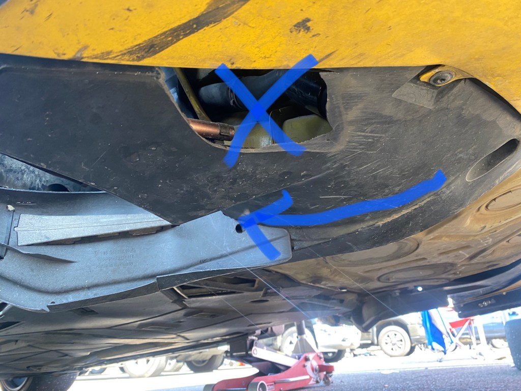
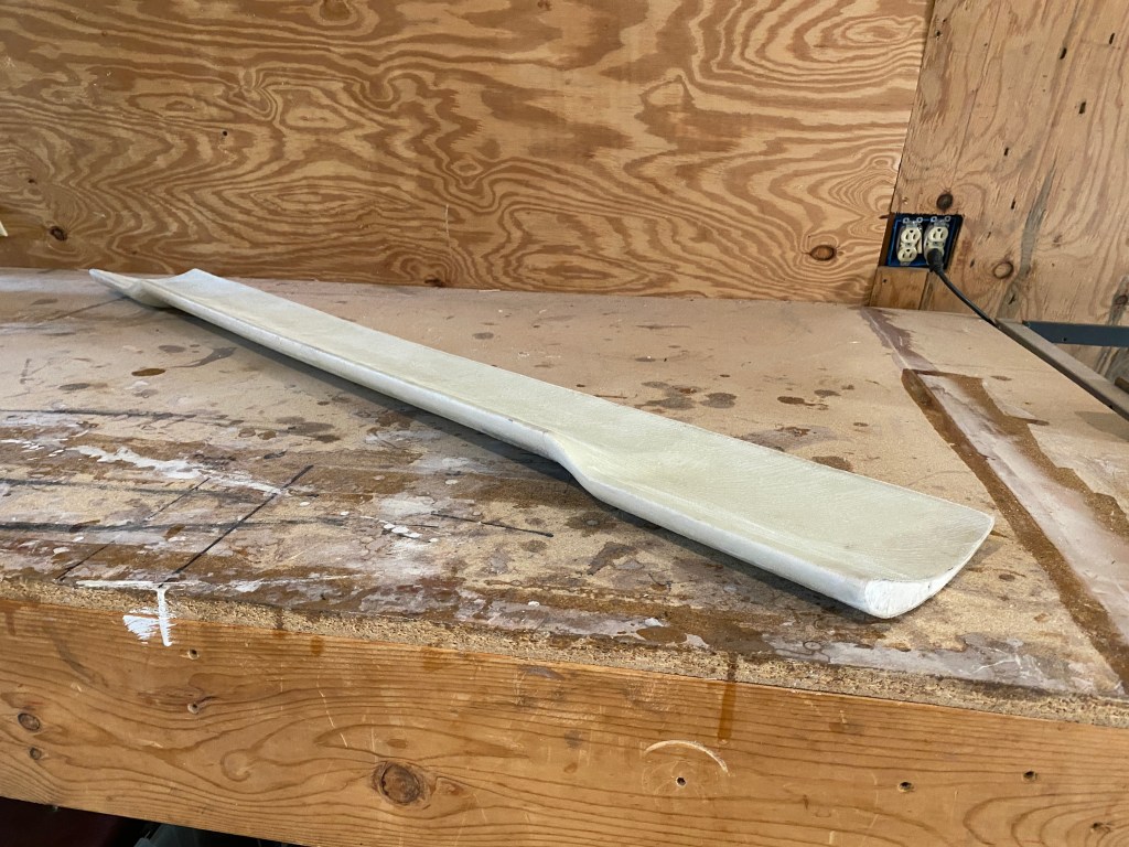
But how effective is a splitter over the OEM undertray? That’s one of the things that I wanted to test out, and so I built a garden-variety splitter. Like 90% of the splitters I’ve seen, it’s dead flat, with sharp edges and no optimization. Kinda like your splitter.
Some racing rules allow flat splitters with some variance to the angle. This is smart, because adjusting the splitter height usually results in some small change in the angle of attack, and so “flat” would no longer apply. But what if you started with a warped piece of wood and attached that level to the ground (or slightly upward)?
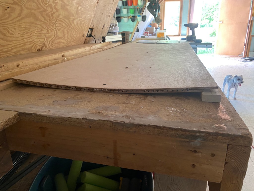
GLTC rules allow splitters +/- 5 degrees. SCCC Time Trials allows +3 degrees for and aft (which I’m taking to mean 6 degrees of curve, wink-wink). A bit of upwards slope in the rear should help diffuse some air, but how much will this improve performance. And what about rounding the front edge, chamfering the rear edge, how much does that help? Well I’m about to find out, because I built a splitter like that as well.
And then there’s my 3D splitter, it has 12 degrees of sweep upwards in the rear, strakes underneath, and other minor tricks.
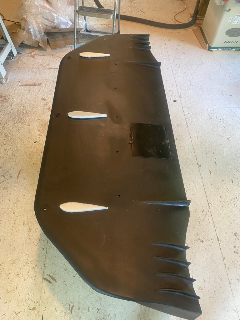
I’m not testing splitter length. I just have too many things to do and didn’t have time to make an adjustable length splitter. The splitters do not extend width-wise past the front fascia, and so I can’t test things like tire blockers, air curtains, end plates, and that kind of thing, either. I also don’t have fender vents or any proper sideways extraction from under the car, so none of the splitters are optimized for extraction.
However, all three of these splitters are the exact same dimensions, and so I’ll be able to test exactly what happens with flat, a mild curve, and an optimal curve.
Five wings and two spoilers
I just got through saying how much more important front aero is, and I’m testing twice as many rear aero options. I like wings, what can I say?
All the wings will be tested with and without a 1/2” Gurney flap. I also made sure all of them can use the same end plates, a rectangular street sign, as is my wont. I’ve brought some other end plates to test as well.
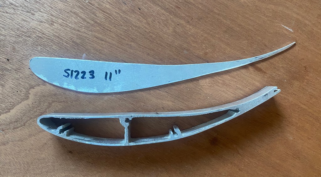
S1223 (586)
My Selig S1223 wing measures 53.3 x 11, or 586 square inches. This is probably the last wing I build based on an aviation airfoil. After finding Enrico Benzing’s wings and what the FSAE kids are doing with those and the MSHD airfoils, all my future wings will probably be car-specific designs.
I built this wing thinking it would be the primary wing on my Veloster. But data may prove otherwise.

MSHD (495)
The MSHD airfoil looks a lot like a S1223 withe more camber. I built this wing using foam and fiberglass, it measures 63.5 x 7.8, or about 495 square inches. The 3D design is specifically for a Miata roofline, so there’s a center section that’s 6 degrees offset from the sides. That’s not ideal for the Veloster, but since this wing is wider than the others, it will benefit from twisting the ends down, even if the angle is isn’t exact for the Veloster.
I built this wing thinking it could be a sellable product, custom built to any roofline. But I have as much desire to do product support as I do to wash the dishes, and so like everything else I build, it’s for me or given away.
9 Lives Racing Big Wang (506)
9 Lives Racing has a great wing, it’s essentially Enrico Benzing’s Be 123-125 airfoil with a slight modification (thicker trailing edge to mount a Gurney flap). I expect it to be quite good, and it won’t surprise me if it’s best in the test. The one I’m bringing is 55”, and just over 500 square inches in area.
I have lots of end plates for this wing, so I might test the vanilla rectangular plate vs the 9LR CFD vs one I designed. I don’t expect to see much difference, but I don’t mind being proven wrong.
Procar Innovations (484)
Procar Innovations has an aluminum wing that looks similar to a TCR wing, which is another Benzing wing, the Be 183-176. PCI shortened the chord and made the wing less aggressive, and in Benzing coordinates this is around 183-155 (18% thickness, 15 degrees of camber). It measures 55 x 8.8, or 484 square inches.
Thanks to Kevin Zhu and Jakob Boedenauer, I’ll be able to pick this one up down the street from the wind tunnel. They use this wing in GLTC, and so it’ll be really interesting to see how three similar sized wings stack up in the 500 square inch class.

MIC 249 vs spoiler
This is a made in China wing that measures 53.3 x 4.6, or just under 250 square inches. If you race GLTC and want a wing in the “free” category, this is it. Justin Lee and I tested one vs a 9LR wing, and the small wing lost. But the story wasn’t over, because I didn’t test this size wing vs a spoiler of the same dimensions.
So I also made a 250 square inch spoiler, and I’ll finally be able to get the data on which is better in this size. It’ll also be interesting to see if a wing with half the area makes half the downforce.
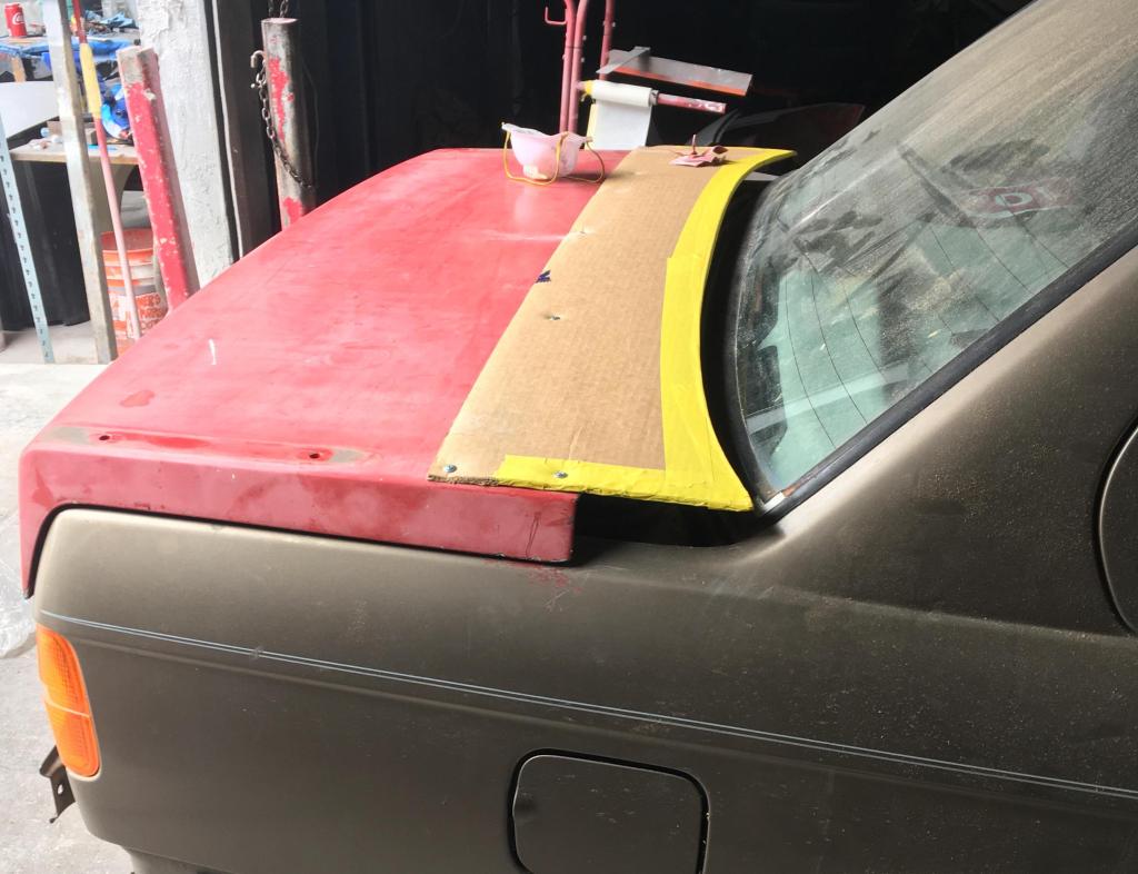
OEM spoiler vs base
Another test I’ll run is the OEM spoiler vs the roof extension on the base model and Turbo R Spec. The OEM spoiler reportedly cancels lift, and measures out at about zero degrees across it. The R Spec roof kicks up a few degrees compared to the roofline but is still pointing downwards at around 5 degrees.
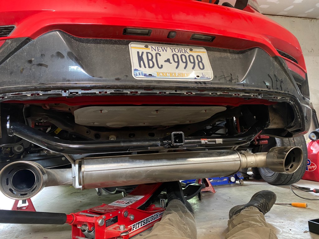
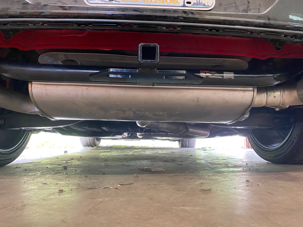
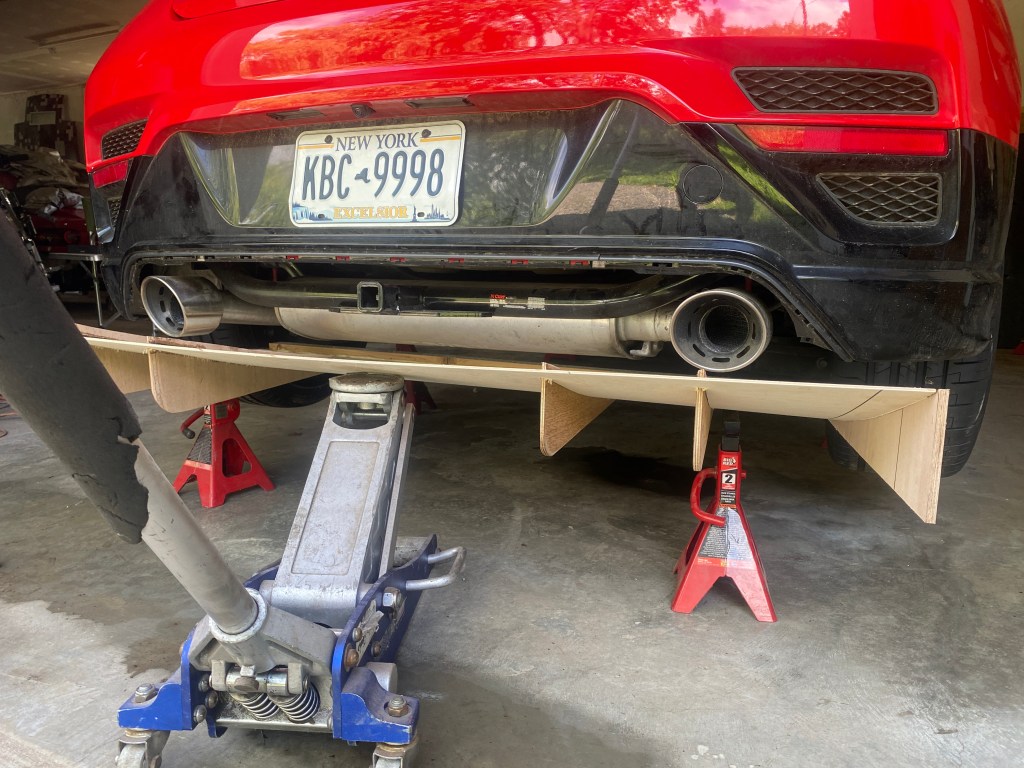
Diffuser
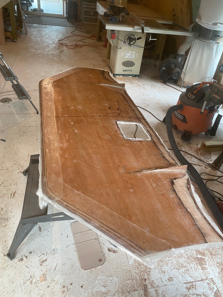
One of the things I’ve always wondered about is a diffuser without a flat bottom. I’ve seen videos, CFD from numerous manufactures, and countless track cars with a diffuser and no flat bottom.
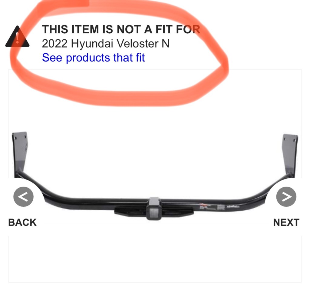
So I made a diffuser just for this test. It installs into the hitch mount and is only wind-tunnel spec, meaning not really roadworthy. It’s as large as most rules allow, and has a few tricks that I’m not going to reveal just yet. If it works, maybe I’ll build a real one.
Hood vents
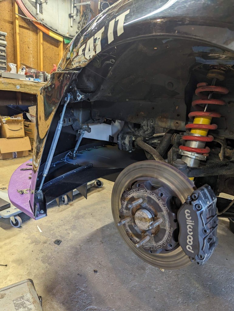
Veloster’s run hot, and so I got a spare hood with an extractor vent. I’m fairly certain this will help cooling, and I enlarged the vent further to increase the effect. I also built a cover for it so that I can A/B test not only the cooling properties, but the aerodynamic properties.

I expect the hood vents will add a small amount of downforce and drag. After I test the temperature on track, I’ll do a full write up.
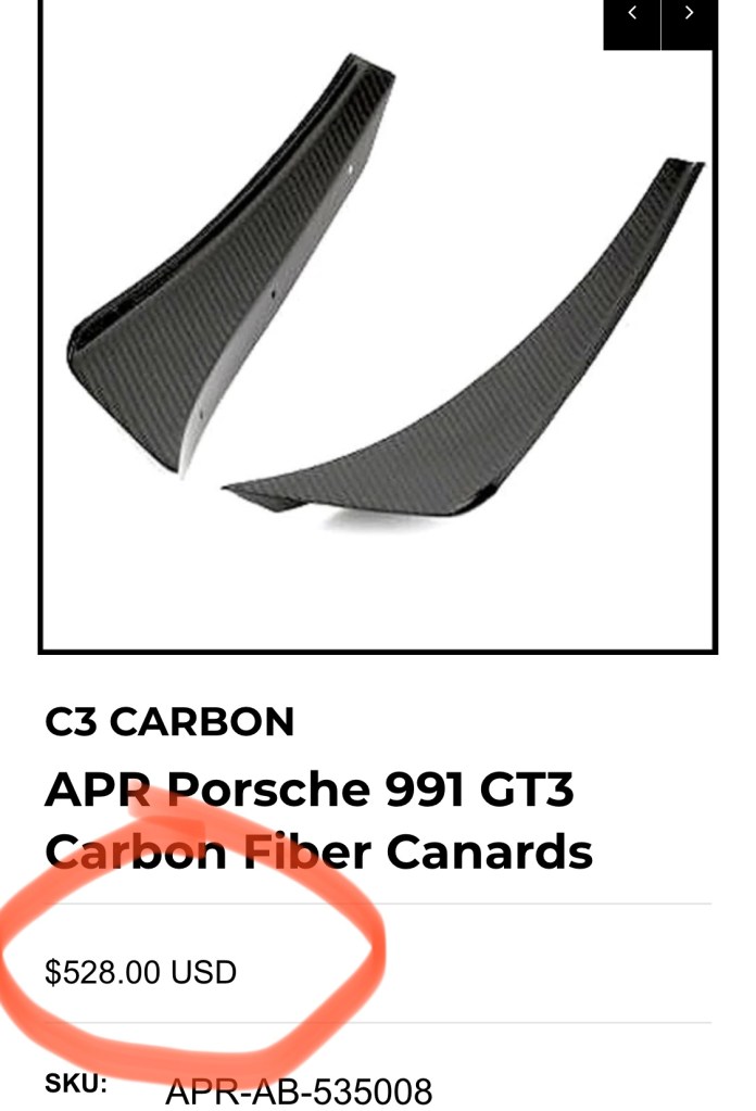
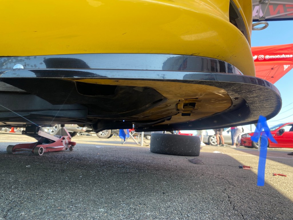
Canards
At the last minute (the morning after posting this article), I decided I needed to answer a question about canards. So I stumbled down to the barn at 4:30am and took a tracing I’d made and transferred that to an aluminum street sign.
I then cut tabs into the mounting side of the canard and alternately bent one up and one down. These would serve as temporary brackets so that I can tape them into place. This is wind-tunnel spec for sure, and if these work, I’ll need to make better ones that mount properly.
The canard design is pretty clever, in my opinion. On the top canard, I use a flat spot by the headlight to gain more surface area, increasing the high pressure side. On the bottom canard, I follow the lines of the air curtain vent, directing more air into the vent. I went for a fairly low angle of attack, hoping to avoid massive flow separations on the back side. We shall see….
Open windows
I’ve always wondered how open windows effects a car with and without aero, and so I’ll test the car with both open and closed windows with the full aero kit, and then again with no aero. I also brought rain guards to see if reducing the open window area will help.
Packing
To transport the parts I bought a 60” aluminum cargo carrier and a waterproof cargo bag, but I needn’t have. As I started loading all the large parts inside the hatch, I realized I could probably get everything inside. The people at the wind tunnel are going to laugh as I roll up like the Beverly Hillbillies, trunk packed to overflowing. Just one more reason to love the VN, so much junk in the trunk.