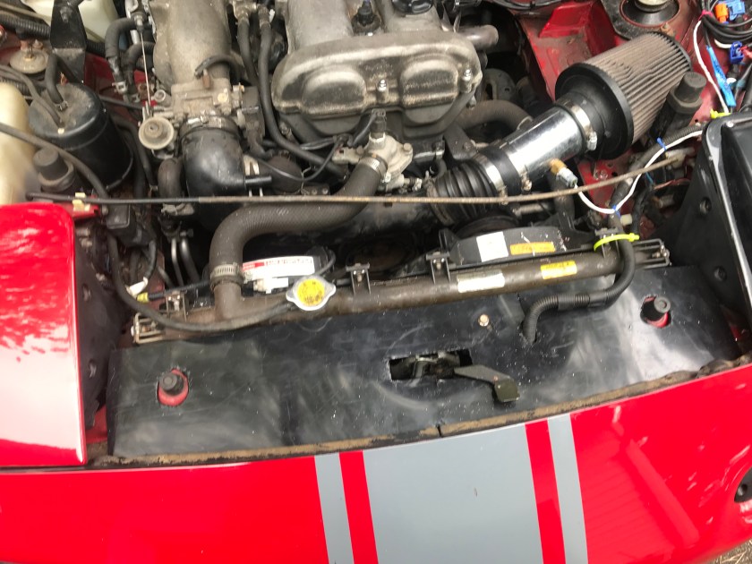
Backstory: I added a Megasquirt PNP2 to my 1993 street car in 2017. I replaced the airbox with a cone filter, and ran the IAT sensor through a tube just after the air filter. This allowed me to get rid of the restrictive AFM flapper valve, but I kept the stock crossover tube with the resonator, which is supposed to fill in a midrange flat spot.
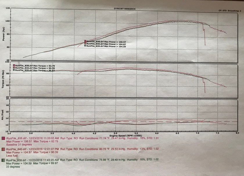
I was pretty happy with that setup because I picked up 4 mph on the uphill front straight at New York Safety Track. Overdrive Automotive in Johnson City dynoed the car, and it made 106 HP. I don’t know what the car was making before, but this is pretty good considering it’s only a Cobalt cat-back, a cone filter, and a Megasquirt PNP2 running on the base map.
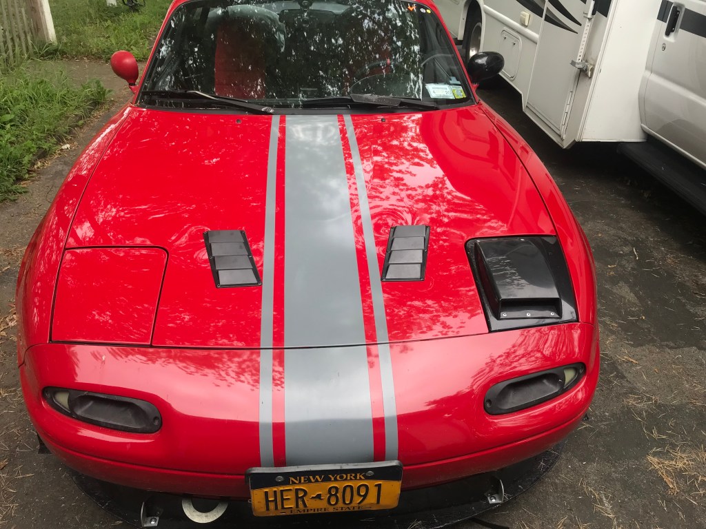
This winter I added a Raceland header and a Magnaflow direct fit cat. I felt like the intake needed more air than just the turn signal intakes, so I put a dorky hood scoop on the headlight. And because all those intakes on the front were probably pressurizing the engine bay and keeping the radiator from working efficiently, I added a pair of $8 hood vents.
The Raceland header doesn’t have a heat shield and I could feel a difference in the engine compartment. I was curious, so I bought a dual element thermometer and put it in different places in the engine compartment. I drove the car around like that, with one sensor at the air filter and the other at ambient temperature. I then put the outside temp sensor in the cowl behind the firewall and the temperature was very close to ambient.

The temp sensor only reads Celsius, converted to Fahrenheit, this is about a 48 degree difference. And this is running the car, not sitting at idle. A rule of thumb is that every 10 degrees F is equal to about 1% in power, so if I could move my intake from the engine compartment to the cowl, I should be able to get almost 5% more power.
Cowl intakes are nothing new, they take advantage of the high pressure zone where the windshield meets the hood. In the image below you can see the arrows mostly point upward indicating lift or negative pressure, but the cowl has significant positive pressure, which brings in cold air. This is a good place for an intake.

I didn’t want to re-use the existing intake crossover. While this might be good for midrange, once the engine compartment heats up , the plastic crossover tube is like a sponge and retains heat, which ruins the whole idea of reducing intake temperature. So I needed to replace the plastic with metal. At the same time, I decided I should move everything over to the cold side of the engine bay, away from the headers.
The first thing I did was see if it would actually fit. I would have to remove the charcoal canister and water bottle for sure, and probably relocate the main fuse box. But it looked like it would fit, so I ordered the parts:
- 2.5″ x 18″ aluminum tubing, $18
- 2.5″ silicone 180 elbow, $42.50
- 2.5″ cone filter, $15
- Universal washer bottle, $19
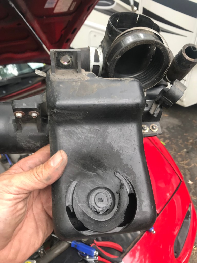
I then started making room for the parts, and as I did, I noticed that the alternator wheel had cut a hole in the back of the crossover tube’s resonator. So much for filling in the midrange flat spot! Note that since the MS PNP2 is a closed loop system, this didn’t make the engine run excessively lean, as this isn’t an introduction of unmetered air, as when running a AFM or MAF.
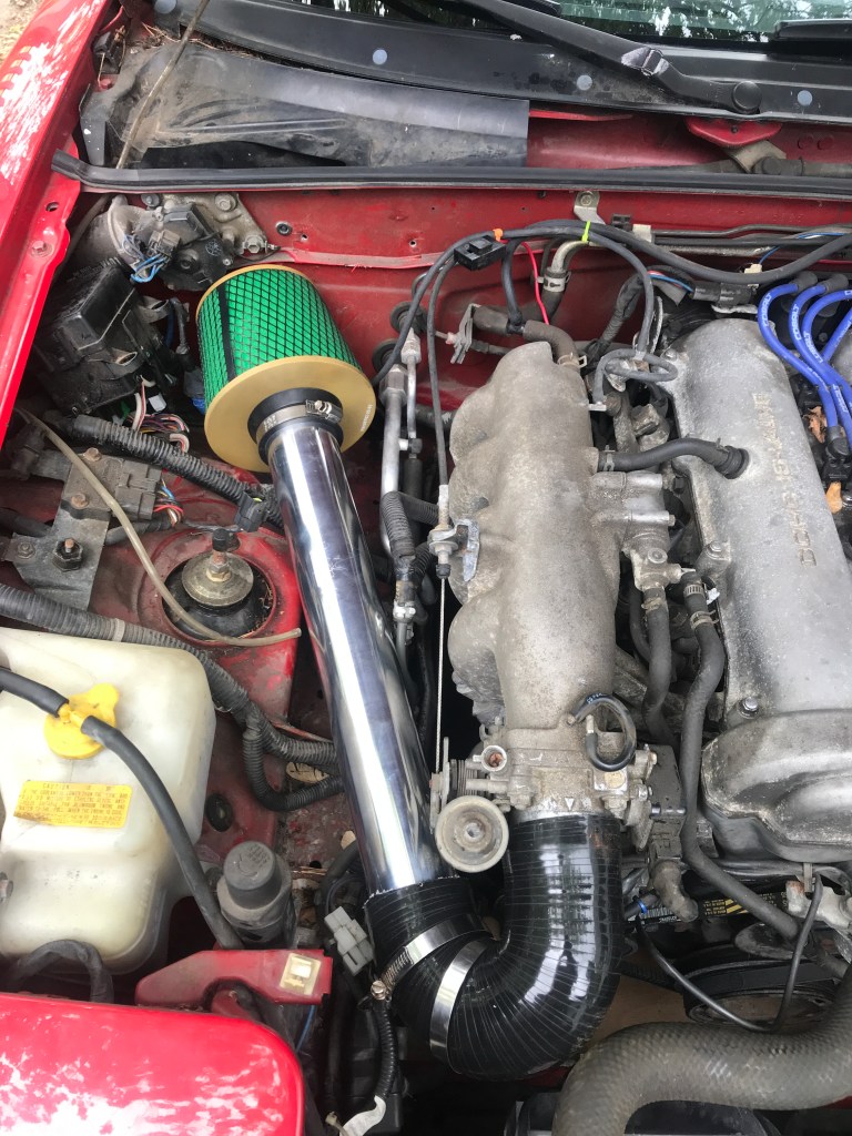
Next I test fitted the parts and found I could snake the aluminum intake tubing underneath the strut tower bar. But only just barely. In the end, I removed the STB, because I’m skeptical of how much it helps, and I wanted a bit more room.
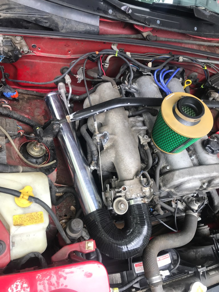
The intake tubing was a bit long, but after trimming the 180-degree elbow, I was able to fit the entire 18″ long tube and filter right up against the cowl. 949 Racing tested different length intake tracts and IIRC a 1.6 made the most power with a 19″ long intake (1.8s should be 21″). Close enough.
Then it was time to finish up some final details.
- Cut a hole in the cowl to feed the air filter. Since the hole is slightly above the filter, I made a small shield to deflect air down towards the filter.
- Put the fuse box bracket and fuse box back in. Can’t believe if fit.
- Clamp all the hoses. Also strap down the intake from moving, using safety wire. It’s a tight fit next to the throttle wheel, and I don’t want the two to make contact.
- Tape up all the holes in the cowl area and screen it off from debris.
- Get rid of the headlight intake scoop and turn signal intakes.
There’s only one final detail, which is to put a new washer bottle on the hot side of the engine. The old airbox location is perfect for a universal washer bottle, which will complete the project. Oh, and I have to dyno it again and report back.

Part 2: Ram Air
That intake lasted about a week and then I decided to change it into a ram air intake. I’d already done one version of this on a 1.8 using the stock airbox and the turn signal. I posted the results some years ago. I measured the manifold pressure using a DIY water manometer (aquarium tubing and a measuring stick), and watched the intake pressure move 4″ of water at WOT. This worked out to about 1% more power at 100 mph.

This time I decided to use the cowl rather than the turn signal for the intake, but once again I butchered a stock airbox to make it work.

I started by cutting the bottom off of a stock airbox and turning it upside down. I then cut matching (ahem) holes in the airbox and cowl. Effectively, I made the entire cowl into an airbox and I’m using the stock airbox mostly to hold the air filter.
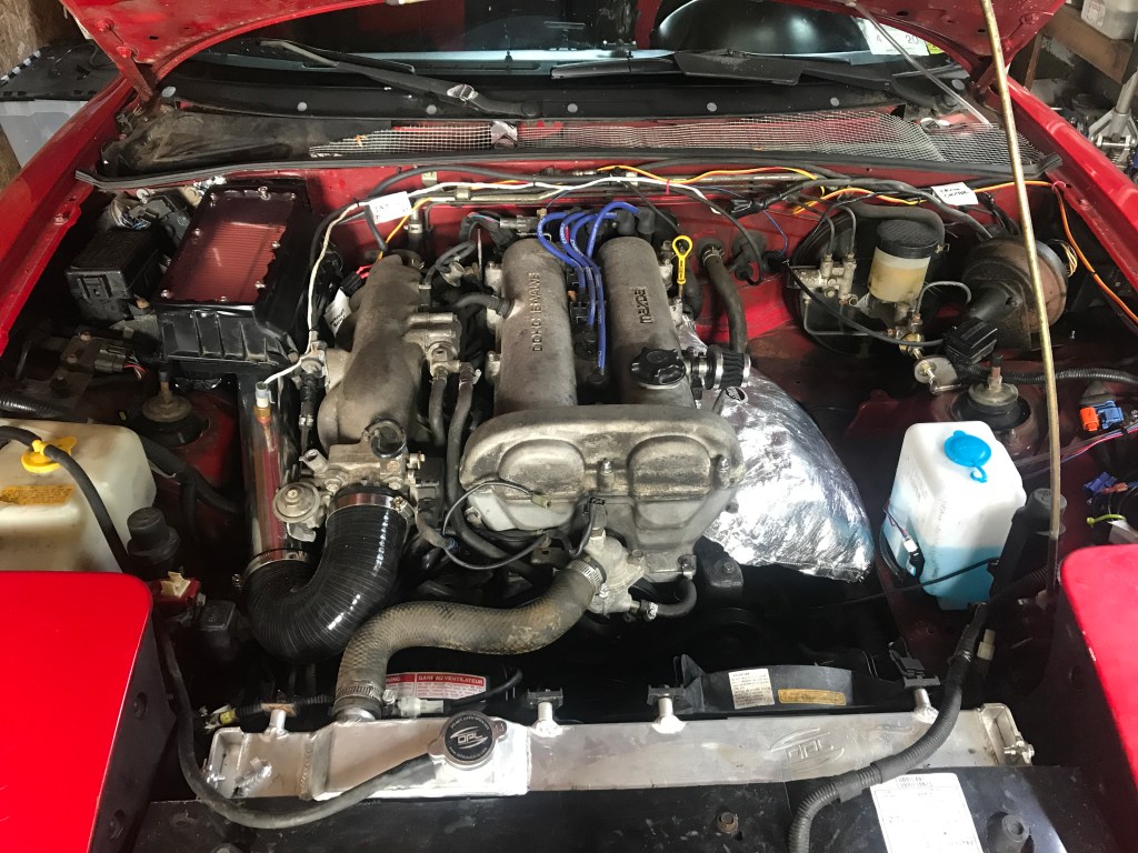
I fastened a clear cover to the airbox, so I can see how dirty the air filter is without opening it. Inside the airbox, everything is sealed up and pressure should build. From experience, I know this will be almost negligible, but it will be fun to measure this and find out.
Mark 2
I decided to make some more changes and this time I’m using the entire cowl as an airbox. (See user comment: this is appropriately called a plenum chamber.) I bought a sheet of Uni foam and put a double layer over the opening in the firewall, and then bolted in a flanged connector on the engine side.

My teammate Jim has a turbo Miata and replaced the intercooler, and so I used those spares to connect the dots. It’s mostly aluminum tubing and should have less heat soak. The 180 bend before the throttle body has a tighter radius than I’d like, but it’s larger than the previous version and part of the incremental improvements.
| Update – I removed the plenum intake, it was super fucking loud. Someone probably appreciates hearing every breath the engine takes, but it was annoying to me. At full scream it was OK, but at idle, low rpm, and cruising around town it sounded like a fat, old man, wheezing and catching his breath at the top of a staircase. That’s being a little unkind to the old man; it was worse than that. |

Version 1 was surely doomed to failure cos the underwood air pressure would be WAY higher than the piss-poor cowl “ram air” effect.
I’d be surprised if there was “ram” there at all.
How ’bout doing another manometer run with 2 tubes….one underhood and the other in cowl (proper name *plenum chamber*)
Comment from GM Body Design cad guy.
What’s WFO?
LikeLike
Corrected WFO to WOT and added plenum chamber. However, I’ve also since reverted the intake, it was loud and I found out I really don’t want to hear every single breath the engine takes.
LikeLike
I’ve been pondering this same idea.
I don’t think I’d need a kick in the dick for motivation, but wonder how much of a difference cutting a hole in the firewall would really make. 1.6l life means I need all the power I can get.
LikeLike
I’ll take a picture of my Mk 3 version of the cowl ram intake and update the post. In the meantime, I think you’ll probably get a similar gain in power that I did. Reducing intake temps is about 1% gain in power per 10 degrees colder. Reducing restrictions in the intake (fewer and more gradual bends) was about 4% total. Ram air didn’t do much until 100 mph, and then it was a 1% power gain.
LikeLike
Patrick, I updated the image and made some comments about the new version.
LikeLike
Out of curiosity, did you measure the temperature difference in the filter location before making the mods? I know that several people run a similar cold-side intake without the cowl box, and was wondering where that might fall. I’d assume that its cooler than the hot-side and not as cool as the cowl, but I’d just be guessing as to where on that spectrum it would fall.
LikeLike
I didn’t measure the cold side before cutting the hole in the cowl. Once I got started making the intake, I just kept going until I was done. I guess I could cover the hole and test it that way, but it’s going backwards at this point.
LikeLike