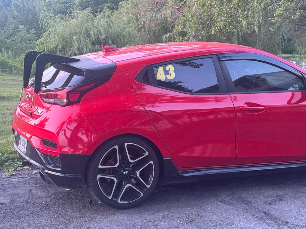
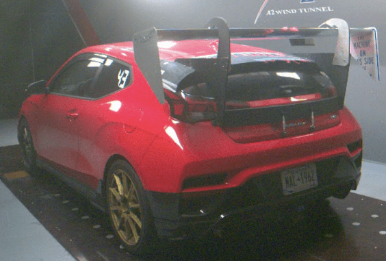
I’ve tested over a dozen wings on my Veloster N, and by this point a sane person would have settled on one of them. But I keep going mad scientist on new ideas, and this monster is my latest creation.
I started this project a couple years ago, before the Wing-Logic MSHD aluminum wing was available. I put this on the back burner for a long time, but recently resurrected it, with the intention of using it for testing low speed aerodynamics.
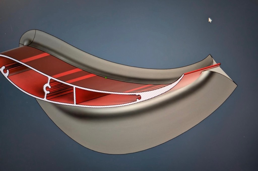
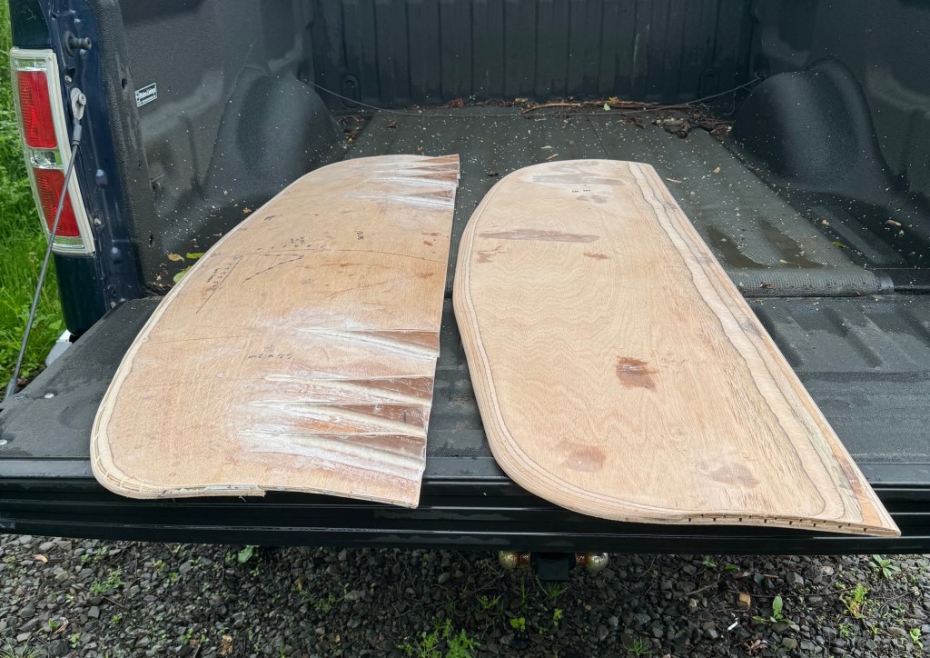
This is the second MSHD I’ve built from scratch. The first was made from 3D printed foam; this one is built sort of like a traditional airplane wing, with a thin skin over a frame of ribs and spars.
The central spar is a multi-lam of marine plywood, and is the main load-bearing member. The endplates and Gurney flap are also made from plywood, while the nose is a solid wood dowel. The skin is thin plywood with fiberglass on top.
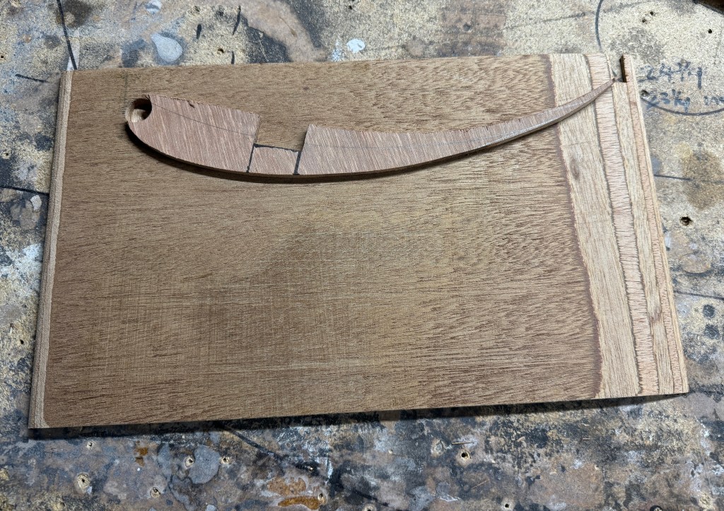
Unlike a traditional airplane wing, I started building this from the outside in. Meaning I began by gluing a MSHD template on the end plates. These were drilled to accept a wood dowel for the nose, and notched for the central spar.
The end plates are an integral part of the construction.
The end plates are 9mm plywood, bull nosed on the leading edge, and knife edged on the trailing edge. The top of end the plate is parallel with the chord of the wing, and so setting wing angle is as easy as putting a level across the top edge.
I may eventually shape the endplates into something more visually interesting, but the rectangular endplates made the building, fiberglassing, and sanding much easier. Because no matter which side of the wing I worked on, the wing was always sitting on a level surface (supported by the endplate), not rocking around on a curved surface.
With the nose and spars supported by the end plates, the next step was the ribs. I cut out several MSHD-shaped airfoils from marine plywood, spaced them out at even intervals along the central spar, and epoxied them into place.
One challenge with the MSHD airfoil is that it is very thin at the trailing edge, which is difficult to build in wood and fiberglass. So I decided I would cheat a little and build a Gurney flap into the trailing edge. This would act as a structural element, while keeping me from fretting over the trailing edge geometry.
This wing is intended for low speed and will be used near the maximum angle of attack, and so a built-in Gurney flap makes sense. The Gurney flap also keeps the trailing edge true, which is a challenge with these DIY wings.
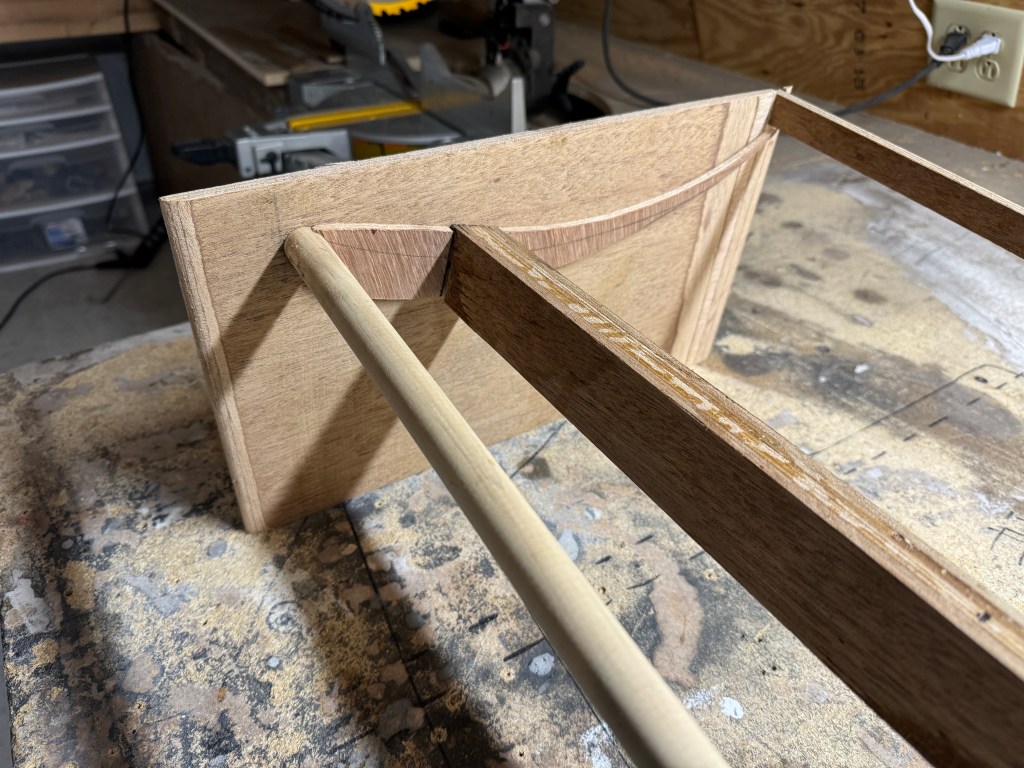
Nose piece dowel, central spar, and Gurney flap are all slotted into the end plate, and will be epoxied into place.
After the nose, main spar, ribs, and Gurney flap were glued into place, I had a skeleton of sorts. The next step was attaching the top and bottom skins. These are made from very thin plywood, glued down on top of the frame. I screwed these down to provide equal clamping force, and then removed all the screws after it set.
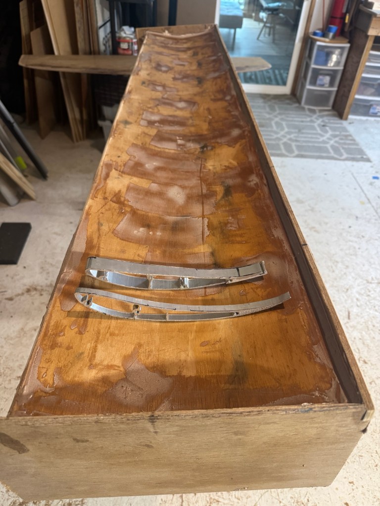
Screw holes filled and getting ready to glass it. From this angle it looks like a box. MSHD 250mm (front) and 9LR Big Wang both look small by comparison.
The plywood skin alone is not strong enough, nor water resistant, so I wrapped the entire wing with two layers of 6oz fiberglass. After that set, I did some minor fairing (filling and sanding), and then painted it.
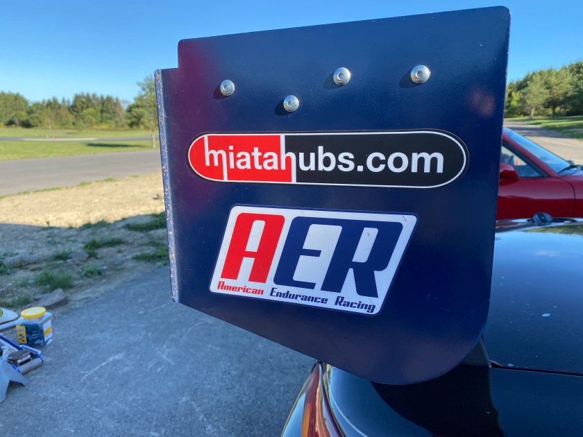
335 MSHD sitting on top of the wing mounts.
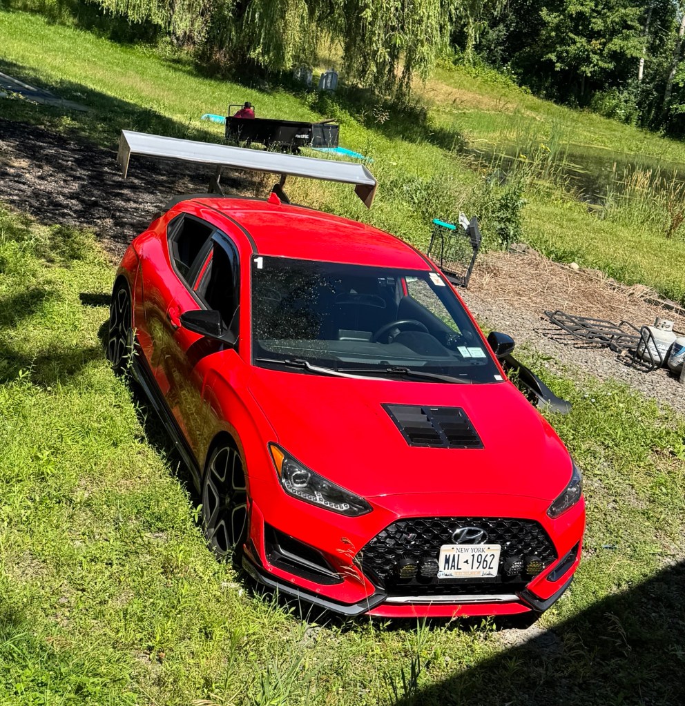
All complete, the wing measures 1800mm x 335mm, or about 71” x 13.2”, for a total area of 937 square inches. The total weight, which includes bottom mounts and endplates, is 6.5 kg, or 14.3 lbs. I was shooting for 6kg, but the second layer of fiberglass and paint pushed it over the edge. Material cost was maybe $100, but there’s obviously a lot of labor involved.
The hatchback wing mounts have a flat top surface that allow me to move the wing forward or back 7” or so. Moving the wing rearwards also increases the height slightly, so I can tune not only the wing angle, but the position as well.
Testing
If you’ve kept up with this blog, you’ll know I tested a few wings at Pineview and NYST last year. Weirdly, the car kept getting faster with more rear aero alone (no splitter or canards).
To recap those results, at Pineview Run, a short single wing (53”x11”) was .7 seconds faster than no wing, and a dual wing (4.7” wing on top of that wing) was 1.3 seconds faster. At NYST, those results were just about doubled, with the single wing being 1.5 seconds faster, and the dual wing 2.5 seconds.
This is weird, because you wouldn’t expect a rear wing to help a nose-heavy FWD car that much. Adding rear downforce at speed should make the front understeer more. But logic, math, and rules of thumbs be damned, more rear aero was more better.
The disbelieving side of me wants to re-run these tests at both tracks. Mass Tuning is at NYST in September, and weather permitting, I’ll back-to-back this new one with the previously tested wings, and report back.
I’ll also A/B test this wing at an autocross, because I want to see what happens at very low speeds. Seneca Army Depot is 25 miles from me, and there are two test and tune events there in August.
In this article I take a deep dive into endplates: why we use them, various design considerations, and then testing different endplates in a wind tunnel. I asked several endplate manufacturers to play ball. Some declined, some ignored, but I was able to secure a good batch for testing, and then borrowed or made what I couldn’t acquire. Across my various trips to the wind tunnel, I’ve now tested over 20 endplates, and this article is the first time I’ve put all that data into one place.
Because these tests cover a few trips to the wind tunnel, I’ll list details about the car and wing each endplate was used on. I always use a standard 12×9 endplate as the basis for the comparisons, and I try to be as scientific as possible.
There’s a lot to cover, let’s get started.
Wings need endplates
You won’t read this in a magazine
Endplates by the inch
144 square-inch shapes
Aviation-inspired experiments
CFD-designed endplates
9 Lives Racing endplates
Yeti Racecraft endplates
Miscellaneous endplates
Conclusions
Side force and center of pressure
Wings need endplates
Endplates improve a wing’s performance, but there are other reasons we use them.
Wing performance – According to Simon McBeath (Competition Car Downforce), wings without endplates lose up to 30% of their performance.
Stability – Moving the center of pressure rearwards makes the car more stable.
Structure – Endplates can be incorporated into the structure of the wing itself, and in a dual-element wing, provide the mounting points and adjustments for the upper wing.
Gamesmanship – Endplates hide the airfoil shape; it’s always good to keep your competitors guessing. Fancy endplates also distract competitors from more important things on your car.
Personalization – Endplates look cool, which is a minor point for some, but the entire point of aero, for others.
In this article I’m mostly concerned with point 1, and to a lesser extent point 2. So let’s jump directly into how endplates affect car performance.
Wings create downforce via the pressure differential between the upper and lower surfaces. At the wing tips, that pressure differential creates a vortex as the car moves forward, because the high-pressure top side wants to move around to the low-pressure bottom side.
Endplates provide a physical barrier, holding the air at the ends of the wing, rather than letting it spill over the sides. This fools the air into thinking the wing is longer (a higher aspect ratio). Larger endplates are better at blocking the air, and theoretically should provide better performance.
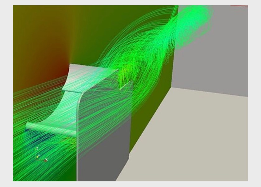
Wingtip vortex with endplate.
You can calculate the benefit of a simple rectangular endplate on a 2D wing using the formula AR = AR_actual (1 + (1.9 * h/b)). Mathematically, this means that aspect ratio (AR) is proportionate to the size of the endplate, or in plainer terms, the larger the endplate, the more it reduces drag and increases downforce.
In reality, I haven’t found that the math works out. In the wind tunnel, changing the size of a rectangular endplate doesn’t get me both drag reduction and more downforce, I get more of both or less of both.
That math formula is for rectangles, and rectangles are boring. Endplates can, and should, be sized and shaped to a specific airfoil. Every airfoil has a different shape and area of its high- and low-pressure regions, and most motorsports wings have a low pressure zone that extends very low and in front of the wing.
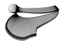
The low-pressure region extends in front of and below the wing. S1223 shown.
As you probably know, the low pressure side is much more important than the high pressure side. Wings make about 70% of their downforce from suction, and so it’s the underside of a car wing that matters the most. This is why endplates extend further below the wing than they do on top, and it follows that deeper endplates should make more downforce.
To gain even more downforce, you can add a small Gurney flap to the trailing edge of the endplate, to kick air sideways. This makes the wing seem like it has more span. You can also bend the endplate such that some air is deflected upwards, which creates downforce.
In addition to the size, shape, and bends on the endplate, you can add vents. Vents are usually in the form of slits or notches cut in the top of the endplate, or at the trailing edge. Although sometimes you see vents on the bottom of the endplate, mixing outside air into the wake. Regardless of where they are, the point of venting is to bleed some of the high pressure air to the low pressure side. This may seem counterintuitive, because lowering the pressure differential reduces downforce. But, if done cleverly, venting can reduce the wingtip vortex, and thereby reduce drag, while not losing too much downforce in the process.
In a nutshell, or perhaps a better idiom is, in this shell game, that’s what endplate design is: trying to get something for nothing. Either you’re trying to get drag reduction without losing downforce, or trying to get downforce without increasing drag.
So how do these different shapes and sizes combine with cuts, vents, Gurney flaps, and bends? Well, that’s what we’re here to find out. Before we dive into it, here are a few things to keep in mind:
All values are listed at 100 mph. The A2 wind tunnel operates at 85 mph, but I use 100 mph as a standard convention (as does Simon McBeath, AJ Hartman, and other people smarter than me).
A gallon of gas is about 6.2 lbs, and so if you see an endplate that makes that much additional downforce, an extra gallon of gas in the tank is about the same amount of additional grip.
One horsepower is about 7 lbs of drag (on the cars I measured here), and so an endplate that reduces drag by say 3.6 lbs gained about .5 hp at 100 mph, which is negligible.
You won’t read this in a magazine
I think I’m the first person to publish an exhaustive endplate test with wind tunnel data. It begs the question, why me? Or rather, why haven’t I read about this already in a magazine? Car magazines will dyno test different air filters, intakes, exhausts, motor oils, etc. They’ll rent track time to test a new 200TW tire as soon as it comes out. But aero testing? Notsomuch.
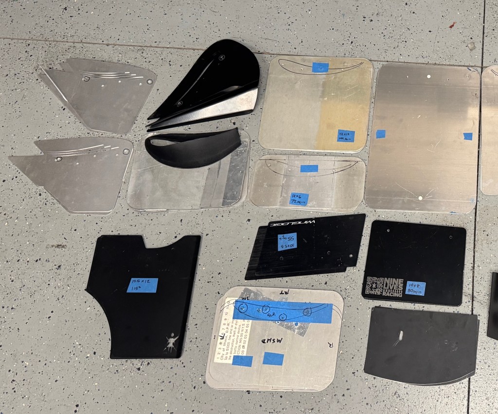
Some of the endplates I tested.
But people also want to know about aero, and one of the most intriguing items has got to be endplates! They are cheap, easy to install, and come in a variety of shapes and sizes. Most endplates are “CFD designed” and if we believe the wild (and unsubstantiated) claims of increased downforce and/or drag reduction, they are a great bang for the buck. Which is best?
I can’t say for sure why car magazines won’t test things like this, but it seems like a combination of the following:
Lack of interest – If you search the archives in GRM, Road & Track, or any other rag outside of Racecar Engineering (which stands head and shoulders above everything else in this regard), you’ll see precious few articles on aerodynamics. I can count them on one hand.
Conflict of interest – Manufacturers place ads in magazines, which puts food on the table. Comparative test only works out for the winner. So if Brand X is a regular advertiser and comes in last place, that’s difficult for the magazine. In the end, it’s probably better to write articles on vinyl wrapping, or HID headlights, or whatever else passes for motorsports these days.
Lack of knowledge – Most car magazines buy parts off the shelf, investigate nothing, and blindly trust manufacturers claims. On the Dunning-Kruger of Aerodynamics, car magazines are firmly in the FanBoi stage: high confidence, low knowledge.
So that’s why you’re not reading about endplate testing in a magazine. But at the price the aftermarket charges for a piece of aluminum, consumers deserve to know what different endplates do for drag and downforce, and ultimately, if they are worth it.
I guess the next question is, if not them, then why me? Why have I taken it upon myself to be the Consumer Reports of aerodynamics? Blame BBTI.
This would be a great time to hit the Buy Me a Coffee link, which supports true investigative journalism, and actual wind tunnel data. The money all goes back into more wind tunnel testing, which results in more articles on this site. Thanks for the support, let’s keep this going.
Endplates by the inch
One of the websites that has inspired my aero research, and this endplate test in particular, is Ballistics by the Inch. BBTI tests the velocity of different pistol and rifle bullets from different length gun barrels. They start with a long barrel, and then progressively cut 1” off it, fire a bunch of rounds to measure and average velocity, and repeat. When the barrel is reduced to a 2″ stub, they move onto another caliber and start over with a full length barrel.
The results show that some calibers, like .223 and 357 Magnum, get much better with a longer barrel, while some, like 38 Special and 45ACP, don’t. This is all down to the propellant (gunpowder) ammo factories use, so you could handload for different results, but it’s still great info for anyone buying off the shelf ammo.
Key takeaways are that short-barrel firearms using slower burning powders produce more flash and noise, but not a lot more velocity. If you have a snub-nosed 357 Magnum, you’re better off feeding it 38 Specials. Conversely, slower burning powders are better in longer barrels. So if you have a 6” 357 Magnum revolver, it has twice the muzzle energy of a 3” barrel of the same.
Good stuff. Useful knowledge. They’ve tested 25 calibers, real firearms vs bench barrels, cylinder gaps, and rifling. The ammo cost alone must have been staggering. Who are the people behind these tests? Are they ammunition manufacturers? Guns and Ammo journalist? Nope. Just a couple of guys who did it for science. They were willing to pay for crates of ammo, destroy a lot of barrels, and spend hours on laborious experiments.
I was doubly inspired by BBTI, not only for doing the Lord’s work on their dime, but also by the whole “let’s keep cutting it shorter and see what happens” methodology.
I wanted to see what would happen if I did that with endplates, but in reverse. So that’s what these first endplate tests are: start with a small rectangular endplate and get progressively larger. I don’t have the time (money) to dick around with 1″ increments like BBTI did, so I decided to make end plates at 3″ intervals: 6″, 9″, 12″, 15”, and 18”.
I didn’t start with a 3″ endplate, as that would have been only half an inch depth under the wing, and that seemed silly based on the size of the low-pressure region. And I didn’t go larger than 18″, for a couple reasons.
I use recycled street signs, and anything over 18″ long means cutting into a 24″x24″ or larger sign, which is wasteful.
I felt that if I extended the endplate over 18″, they might bend inward at the bottom. The aluminum signs I use are quite sturdy, but I’ve seen this bending on my buddy Bronson’s car, and it looks like anti-performance.
Very large endplates are going to have considerably more side force. Meaning that they would move the center of pressure rearward, and that might have a greater effect on handling than whatever the endplate is doing to the wing’s performance. That’s a separate topic, and difficult to discuss without knowing the weight balance and silhouette of the car in question.
Simon McBeath published a similar test in Racecar Engineering, using CFD. He started with a small rectangular endplate and then increased the depth of the endplate by 50mm each time. He stumbled upon magical in-between size (125mm IIRC), which outperformed all the others. Keep this in mind, because it kinda happens later in the test, as well.
I won’t republish Simon’s results here, subscribe to Racecar Engineering and you can find that article in their archives. If you want to cross-list my data with Simon’s, note that Simon measured the depth below the wing, and I use the total endplate height. My endplate depth is about 2.5″ less than the total height, so a 6″ end plate has about 3.5″ of depth.
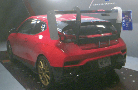
Note that I did the rectangular endplate test on my Veloster N with a 71″ Wing-Logic MSHD. I used reverse swan neck wing mounts mounted at roof height, with the usual quarter-chord overlap over the rear hatch. I feel the wing was high and wide enough that the body shape didn’t make much difference on the endplate performance, but it’s always worth noting that the car influences the wing and endplate.
The following table is listed in pounds (I’m embarrassed that I can’t think in metric; I’m too old to make the switch). Positive values are bad, negative values are good: less drag or less lift (= downforce). I list the total Lift, which is the lift at the front (Lift F) and rear (Lift R) added together. Rear downforce and drag can lift the front of the car, and it’s interesting to see that relationship here. I’ve also included a column for the L/D ratio the car, and how that changed with each endplate.
Endplate
Drag
Lift
Lift F
Lift R
Car L/D
12×6
-0.5
1.5
0
1.5
0.88
12×9
0
0
0
0
0.88
12×10.5*
1.1
-0.8
0.35
-1.15
0.88
12×12
2.2
-1.6
0.7
-2.3
0.88
12×15*
4.7
-2.55
1.15
-3.7
0.88
12×18
7.2
-3.5
1.6
-5.1
0.87
Rectangular endplates.
Let’s take a look at that results in detail:
12×6 – The smallest rectangular endplate reduced drag by .5 lbs and lost 1.5 lbs of downforce. Not a great tradeoff, but also these are tiny numbers, and if you have 6″ endplates now, there’s no reason to “upgrade” them.
12×9 – This is a street sign cut in half, and is the endplate I put on every wing, to baseline the testing of other endplates. Its values are all zero, because everything else is being compared to this one.
12×10.5* – I didn’t test this size, the values in the table are an average between 9″ and 12″, which is a fair assumption given the data. I included this in-between size because it’s the same dimensions as the 9 Lives Racing Megga endplate, which, if we believe the advertisement, is supposed to increase downforce by 10%. I’ll be kind to 9 Lives Racing and compare the Megga-sized endplate to the 6″ rectangle, and you can see the larger endplate increased downforce by 2.3 lbs. Given that the wing is making about 260 lbs of downforce, this is less than 1% more downforce than a 6″ endplate. Claiming 10% more downforce is 1000% wrong.
12×12 -This is the maximum area allowed in NASA Super Touring, and I’ll go into more detail about that in the following section. It makes 1.6 lbs more downforce than the 9″, and trades that for 2.2 lbs more drag. These are nothing numbers, which is why the L/D ratio of the car didn’t change.
12×15* – I didn’t test this size for financial reasons, the values in the table are an average between 12″ and 18″. This seems a fair assumption based on how little things change, and there’s no reason to use this size IRL.
12×18″ – This is a full-length street sign, and made the most downforce, but also added 7.2 lbs of drag, which is equivalent to losing about 1 hp at 100 mph. The endplates bent inward from the suction below the wing, and this can’t be good, because this is the only endplate that changed the L/D ratio of the car, and it did so in the wrong direction. The A2 wind tunnel operates at 85 mph, and so at a higher speed, you’d see even more bending, and probably less efficiency.
You can see the 18″ endplate bending inward at the bottom. Some of this may be influenced by the location of the wing and body shape. For aerodynamic efficiency, the 18″ endplate was worse than all of the others.
After reviewing all of this information, it appears that every 3″ of depth adds about 1.5 lbs of downforce, but it also adds proportionately more drag. If we remove the 18″ endplate from the test, I can conclude that different sized rectangular endplates result in the same L/D of the vehicle.
In my testing, I found two exceptions to the above statement:
We tested a 300×300 mm endplate (close enough to 12×12) endplate on Raul’s BRZ with a 68″ PCI wing, and the large endplate lost over 20 lbs downforce compared to a standard-sized flat rectangle. For whatever reason, on this wing, on this car, bigger was not better; it was quite a bit worse. I didn’t include this data in the preceding table, because I didn’t test my street sign endplate on his car, but something a little different in size. Anyway, avoid this size on a PCI wing.
In this experiment, I didn’t find a rectangular endplate that was too small, but later in this article, the trapezoidal Wing-Logic endplate also underperformed compared to a 6″ rectangle.
Both of these were outside the Goldilocks zone of “not too big, not too small” and if I were to make a rule of thumb about rectangular endplates, I’d say make them about a chord in height. If you have a 9″ wing, then a 9″ tall endplate is about the right size. Unless you stumble upon some magical size, then going significantly over or under a chord’s height could be a lot worse.
300×300 endplate was too large and oddly lost a lot of downforce compared to a smaller endplate.
144 sq-in shapes
NASA Super Touring rules specify a 144 square inch limit for endplates. Go over that size, and your car is illegal. The rule leads people to believe that bigger is better, but as we just saw on Raul’s PCI wing, bigger is sometimes a lot worse.
It begs the question, why did NASA create this rule? If you look at the rest of the rulebook and the aero values, it’s pretty obvious that guessing at aerodynamic performance, and not measuring it, is their modus operandi.
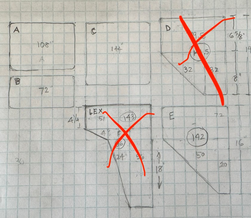
But let’s put that all aside for a moment and say that you want to maximize your endplate size for the NASA ST rules, the easiest way to do that is a square 12″ x 12″ endplate. But there are other size rectangles that result in the same 144 square inches. Indeed, there are other shapes that result in the same area, but that extend further below the wing. Theoretically, this should produce more downforce. Maybe we can get something for nothing?
I drew up a few endplate designs and sent them over to Tim Miller, and he suggested I try a delta shape with a long axis of 16″. This came out to 142 square inches, but close enough to 144.
I compared C to E: similar area, different shape.
Now you might be wondering which way the end plate faces? It’s a good question, and so I tested it both ways, delta forward (with the taper facing forward) and delta rear (with more surface area forward).
Note that the car, wing, and position of the wing are all the same as in the rectangular endplate tests. But this time I’m using the 12×12 as the basis, because it’s all about the max NASA size.
Endplate
Drag
Lift
Lift F
Lift R
Car L/D
12×12
0
0
0
0
0.88
Delta forward
2.1
-1.6
-0.2
-1.4
0.88
Delta rear
1.9
-2.5
0.4
-2.9
0.88
144 square inch shapes compared
12×12 – This is the basis for the comparison, and so all its values are zero.
Delta forward – The endplate was placed such that the tapered edge faced forward, with more surface area to the rear. This made 1.6 lbs more downforce than the 12×12, but also more drag. End result, no discernable difference.
Delta rearward – The same endplate flipped around so that it had more surface area forward, made more downforce. This makes sense, since much of the low-pressure region is ahead of and below the leading edge of the wing. What’s surprising is this direction also had less drag than the other way around. I’ve been saying this for years, that endplates should be designed with more surface area forward, and I feel vindicated with this evidence. But also, these are such small numbers that it didn’t change the L/D ratio of the car, and whatever point I was trying to prove is pointless.
This is the delta forward direction.
At this juncture I can conclude that that any rectangular endplate from 6″ to 12″ tall, and probably any 2D shape, will result in the vehicle having the same aerodynamic efficiency. Unless you go too small or too large, or somehow luck into a size that has magical abilities, endplates of different sizes and shapes are just tiny tradeoffs between drag and downforce, and all of them amount to the same aerodynamic efficiency.
So if all 2D shapes and sizes are the same, what about 3D shapes?
Aviation-inspired experiments
I wanted to try a couple different endplate ideas based on things I’ve seen on aviation wings. These tests were on the Veloster with the 71″ MSHD, reverse swan necks, etc.
Airfoil shape – The first experiment was to use an endplate that’s shaped like an airfoil, with a thick leading edge, tapering back to a sharp trailing edge. I made this out of foam and covered it with tape, and then stuck it to a 12×6 endplate. I eyeballed the shape, it was probably close to a Clark-Y. Theoretically, this should work better when the wing is in yaw (going around a corner), as the rounded leading edge should have better flow attachment, and the shape of the airfoil should kick air a little more sideways, making the wing seem like it has a higher aspect ratio.
Fillets – The other thing I wanted to try was to reduce the intersection drag between the endplate and the wing. You see this on airplane wings, at the wing root. That 90-degree corner where they meet is a place where flow separates, and radiusing that area should help flow attachment. I had my friend Alyssa 3D print me some plastic fillets with a radius.
Rounded fillet idea was better on paper than in the wind tunnel.
While both of these ideas sounded great in theory, neither of them worked out.
Endplate
Drag
Lift
Lift F
Lift R
Car L/D
12×6 plain
0
0
0
0
0.88
12×6 airfoil
-1.3
26.8
8.8
18
0.79
12×6 fillet
-4.8
24.7
9.7
15
0.81
12×6 – This is the plain rectangle I used in the endplates by the inch test. All of its values are zero, because the other endplates are based on this.
Airfoil – Making the endplate thicker and shaped like an airfoil reduced drag, but it also lost 26.8 lbs of downforce compared to the unadorned street sign. The aerodynamic efficiency took a dive, down to .79. Ouch.
Fillet – The fillet reduced drag even more, but downforce went down by almost 25 lbs. For a low-drag application like an airplane, where maybe lift is not the primary concern for long distances, perhaps this is a good idea. But for a car wing, not at all.
In retrospect, the airfoil shape was probably too thick, and reduced the effective length of the wing by 3″, which was the thickness of the airfoil, and about 4.5% of the span. Total downforce went down by 11.5%, which means there was still an unfavorable tradeoff between drag reduction and downforce. The airfoil shape would be most effective when placed in yaw, but I didn’t test that. There may be some benefit to thickening and rounding the leading edge, but not at the expense of reducing the area under the wing!
The fillet under the wing also shortened the effective wing length, and that’s probably why it lost downforce. It’s a similar problem to the airfoil shape. If I redesigned this, I’d radius only the trailing surfaces after the thickest part of the wing.
But neither one of these is a game changer, and in fact both were utter crap. The theme of “you get drag reduction or downforce, but not both” remains true.
CFD-designed end plates
My guesses at improving endplate design were interesting but not fruitful. Taking my ideas and shaping them into reality, and then testing them in a wind tunnel, is a slow and expensive process. People smarter than me do their development in CFD. This allows them to try many different iterations on the computer, and arrive at an acceptable tradeoff between drag and downforce.
But there are three common problems I see with the CFD approach.
Testing – Nobody seems to test their CFD-designed endplates in a wind tunnel. They think (or rather, want you to believe) the CFD is valid, when in fact it’s never been calibrated by putting it into a feedback loop. “CFD-proof” isn’t proof; if you see those words you are being scammed.
Free stream – Most of the CFD I’ve seen is done in free stream. The fact is, endplates should be designed not only for a particular wing, but for a specific car, with an exact wing size and wing location. If you test wings in free stream, meaning that the wing is suspended in air, but not attached to the car, you can absolutely design the most efficient endplate for any given wing. But when you put the wing on the car, the game changes entirely. Developing endplates (or any aero device) in free stream CFD and applying that to all cars is utter bullshit.
Wing efficiency vs vehicle efficiency – Cars are large and draggy, and have shitty aerodynamics. In order to improve the L/D ratio, you need to make huge changes to downforce, not small changes to drag. Adding more wing angle makes the wing less efficient, but it makes the vehicle more efficient.
But if CFD isn’t real, the wind tunnel isn’t real either. In the real world we have winds from every direction, cars in front of us, and in the situations where when we want the most downforce, in a corner, the car is in yaw.
I didn’t test those things, and they are certainly important. So as much as I might malign CFD for giving us false hopes, I’m also acknowledging that wind tunnel testing isn’t 100% accurate, either. We are all doing the best we can, with the information we have available.
I tested CFD-designed end plates from Yeti Racecraft and 9 Lives Racing, which I cover below. At the wind tunnel we also tested some CFD-designed top secret endplates I can’t show any pictures of. The results were exactly in line with all of the other CFD-designed endplates, with their fancy vents, cuts, and shapes, and so I’ll wrap up that in the final conclusion.
9 Lives Racing
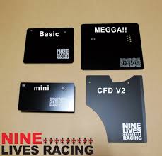
9 Lives Racing sells four endplates, three rectangles of different sizes and a CFD-designed shape that has a couple cuts and a bend in it.
The basic endplate measures 10” chord by 8” depth. The wing is positioned at the rear of the endplate, so that the trailing edge of the wing is at the rear edge of the endplate. This puts most of the endplate’s surface area in front of and below the wing, which is proper.
The mini endplate looks to be the same as the basic, but with less depth. I didn’t test this one, but I’d guess it performs similarly to the 6” endplate I tested.
The MEGGA!! endplate is larger than the basic in both directions, measuring 12” chord and 10.5” depth. I already covered this size in the Endplates by the Inch section.
The CFD V2 measures 10.5″ chord by 12” depth with a semi-circular arc cut into the leading edge and a vent cut into the top side. It measures about 115 square-inches, well under the silly 144 square inch NASA Super Touring rule.
Years ago there was a CFD V1 endplate, which had the same shape, but without the bend on the trailing edge. Based on the shape of the low pressure region below the wing, this semi-circular cut seems like it would reduce downforce, just the way that the Delta-shaped endplate I tested showed that more area forward was better than more area reaward. Anyway, I tested CFD V1 on a previous trip to the wind tunnel, and I ran it in both directions to test my hypothesis. I’ll include that data in the summary table.
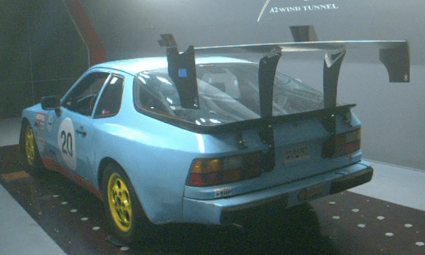
Note that the these endplates were tested on two different cars, my Veloster N with a 55″ 9LR original (Express) wing, and Pete Mink’s Porshe 944 with a 68″ Evo wing. I didn’t include a vehicle L/D ratio column in the table, because I can’t relate it to both cars. In any case, you can probably guess that the vehicle L/D didn’t change much.
Endplate
Drag
Lift
Lift F
Lift R
12×9 rectangle
0
0
0
0
9LR Basic
0.8
-7.2
1.2
-8.3
CFD V2
1.1
-3.7
-1
-2.7
CFD
4.1
-1.8
-0.8
-1
CFD reversed
3.5
-1.5
-0.4
-1.1
12×9 – Street sign cut in half, everything here is compared to this.
9LR Basic – What’s super interesting about this endplate is how well it performed compared to the 12×9. It has 2″ less chord and 1″ less depth, and yet it made 7.2 lbs more downforce. Drag went up, which is what happens when you add downforce, but by less than 1 lb. Nevertheless, this is better performance, and if I had to guess, I think it has to do with a) stumbling upon a “magic” size, and b) positioning of the wing on the endplate. On the street sign endplates, I centered the wing fore and aft, but on this endplate, the wing is as far rearward as you can put it. This endplate shows that a proper rectangle is as good, or better, than most anything.
CFD V2 – Compared to the Basic endplate, the CFD V2 makes less downforce and more drag. Which is odd, because their advertising claims the CFD V2 makes 10% more downforce and 7% less drag, and it’s actually worse in both directions. But maybe they were comparing that to no endplate at all? In any case, the Basic is better.
CFD V1- I tested the first version of the CFD shape on my Veloster, and it made more downforce than the 12×9 street sign, but also more drag. When I reversed the endplate on the wing (the holes didn’t even match up, so the endplate was askew), the numbers were slightly different, but basically the same. This is no surprise, since we saw this already with the Delta-shaped endplates, putting them forward or backward didn’t move the needle. So it’s expected that the same result happened here.
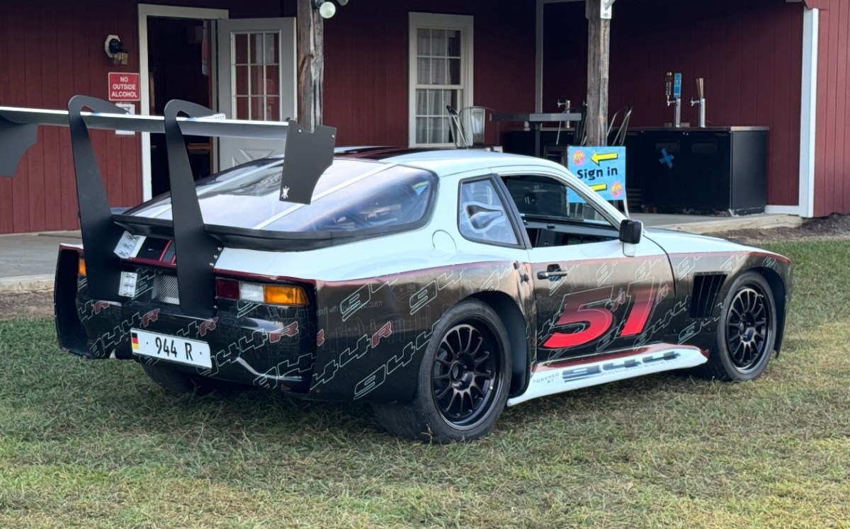
9LR CFD V2 on Pete’s 944
Two things of interest came out of this test, one is that there is sometimes a sprinkle of magic in rectangular endplates, and one size may work slightly better than others. Simon found this in his CFD experiment, and I’ve found the same in this test, both in sizes that work better than they should, and sizes that are quite a bit worse. Now we are only talking about a difference of 7 lbs of downforce at 100 mph, and that wouldn’t change the performance of the car in a way that you’d notice. Still, it’s neat to see this.
The other interesting tidbit is the difference between the CFD original and CFD V2, with the rear bend on it. The rear bend added 2 lbs of downforce and reduced drag by about 3 lbs, and is an obvious improvement. While these are tiny numbers, they are at least going in the right direction. But the Basic rectangular endplate still outperformed both V1 and V2.
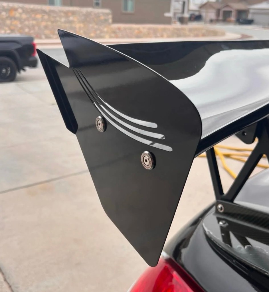
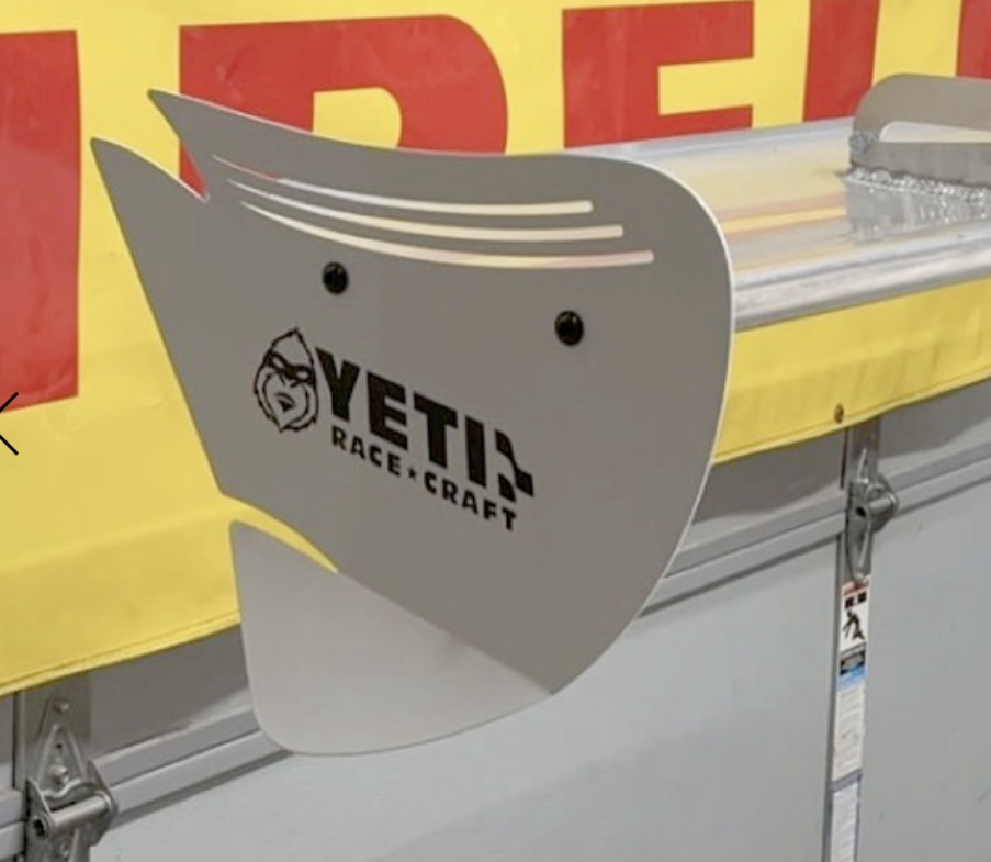
Yeti Racecraft
Yeti Racecraft is an aftermarket manufacturer making CFD-designed endplates and other aero parts. Yeti’s Brian Kemerley designs each one specific to an aftermarket wing. Meaning that Brian’s endplate for a PCI wing is a different size and shape as the one he makes for 9 Lives, which is different from the one he designs for Wing-Logic. This makes sense because the pressure distribution is going to be a different size and shape on different wings.
But the endplate shapes aren’t hugely different, they all have the same family resemblance, with more surface area forward than aft. A rectangular endplate forms a vortex on the corners, but Brian’s “swoosh” shape merges two vortices into one, which results in less drag. There are vents cut into the top, to bleed some high pressure air to the low pressure side, and a long tail with a notch in it, presumably to do the same.
I tested this model, both with and without the rear flick at the trailing edge.
Some of the Yeti endplates are flat, and some have a small Gurney flap on the trailing edge. Unlike the 9LR CFD V2 endplate, the Yeti bend is only on about half the trailing edge. In the data below you’ll see that this worked, although I wonder how it would have performed if the lower half had the flick on it, rather than the upper half.
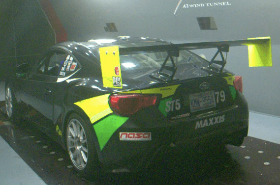
These endplates were all tested on a Porsche 944 with a 68″ 9 Lives Racing Evo wing and their standard wing mounts. As a side note, I helped Pete install the wing mounts and I found them to be well designed and constructed.
Endplate
Drag
Lift
Lift F
Lift R
Car L/D
12×9 rectangle
0
0
0
0
0.64
Flat swoosh
-0.9
-0.1
-0.3
0.3
0.64
Flick swoosh
0.2
-4
0.5
-4.6
0.65
Time Attack
5.9
-16.7
5.8
-22.5
0.69
12×9 – Same rectangle, baseline for others.
Flat – The swoosh shape, topside vents, and rear notch combined to do… not much. Compared to the basic 12×9 rectangle, the fancy shape had 1 lb less drag and .1 lbs less downforce. These are barely measurable figures, and no better than a generic rectangle, and worse than a 9LR basic.
Flick – The same shape with a half-length Gurney flap gains 4 lbs of downforce and .2 lbs of drag. That’s so little drag that we can ignore it, and call it a 1.5% gain in downforce for free. Well, not exactly free since the endplates cost $175, but this is an actual performance gain, not fantasyland. But still the 9LR Basic was better.
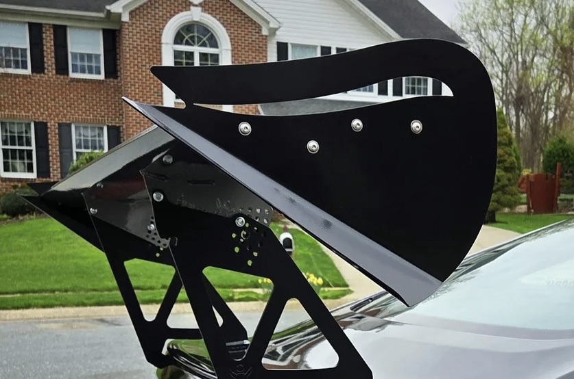
Time Attack – This endplate has a much larger top vent and a radical double bend at the bottom edge, which scoops air almost like an outboard wing. It made 16.7 lbs of downforce and added 5.9 lbs of drag. That’s a 2.8:1 L/D tradeoff, which is remarkably good. This is slightly better than the L/D you see when adding Gurney flap to a wing.
Yeti Time Attack endplates have a large scoop at the bottom, almost like a mini wing.
I have a knee-jerk reaction against CFD designed endplates, because most of what I’ve seen is an expensive product, supported by misleading claims, and a zero-sum result. But Yeti Racecraft has made at least one endplate that proves Brian can design a CFD endplate that outperforms everything else.
Given all the data on different shapes and vents so far, I’m not going out on a limb to say that the performance isn’t based on the shape of the endplate, but how the shape works in conjunction with specific bends Brian puts in the endplate. This isn’t magic or luck, but the kind of thing one arrives at by many hours of CFD work. You can’t copy this shape, send it to SCS, and get the same performance as the Yeti Racecraft endplate.
And shame on you for even thinking of that! Many hours of development time went into this endplate, and stealing someone else’s work makes you a thief. So if you want these endplates, buy them from Yeti and get the real deal. Don’t be an asshole and copy something that won’t perform as well, because you don’t know where to put the bends, how much to bend them, and how that changes for different airfoils.
OK, one nit: the description on the Yeti site says this endplate also reduces drag, and while that may be true in the CFD, it’s not true in the wind tunnel. No endplate adds downforce and reduces drag. But what is true is that this is an excellent endplate, that results in better vehicle efficiency than any other endplate I tested. Bravo.
Yeti’s CFD shows how effective that bottom bend is, effectively making the wing seem like it has more span. That it does this with such a favorable L/D ratio is astounding.
Yeti also makes a hybrid shape that combines their basic swoosh shape with a less aggressive bottom bend than the Time Attack. I didn’t test this one, but it probably sits somewhere between their Time Attack and swoosh-flick.
I didn’t test this one, which combines the Yeti swoosh shape with a less aggressive Time Attack bend.
At the end of this article I give each endplate a grade, and the only thing keeping the Yeti Time Attack from getting an A+ is a couple adjustment holes. With an endplate like this, when you adjust the angle of attack on the wing, it also adjusts the angle of the “winglet” on the endplate. So I’d like to see adjustment holes here, so that the endplate can be pivoted a few degrees fore and aft.
Miscellaneous endplates
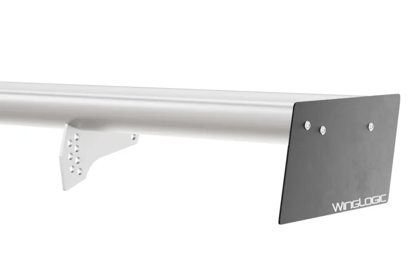
I’m going to add three more endplates to this discussion, the first is the endplates that come in the box when you buy a Wing-Logic MSHD, the next is the basic 12×9 street sign with a bottom vent, the last is an endplate I made back in 2019.
The Wing-Logic endplate is a 10×5.5 parallelogram. This is the smallest endplate in the test. It doesn’t come pre-drilled, and so I placed the endplate about where I placed the rectangular endplates, with most of the area below the wing.
The next one is the standard 12×9 street sign, with a single slash cut into the bottom of the endplate, and then bent such that it directs air from the outside of the endplate into the wake behind the car. The purpose of this is to (theoretically) reduce the trailing vortex and reduce drag. There’s no picture of this one, not because it’s a secret, but because you don’t want to do it.
Finally my Occam’s Racer endplate was one I made back in 2019. I shaped it so that there’s more area forward and less at the trailing edge. I put a notch in the top side trailing edge, because I’ve seen that on other endplates, and I bent a small 90-degree Gurney flap into the trailing edge.
Occam’s Racer endplate on a 9LR wing.
The endplates were tested on different cars and with different wings, but I did baseline the 12×9 endplate on every comparative test, and so we can have a valid discussion about the results.
Endplate
Drag
Lift
Lift F
Lift R
12×9 rectangle
0
0
0
0
12×9 vented
2.8
-2.4
.8
-3.2
Wing-Logic
4.2
11.3
7
4.3
Occam’s Racer
6.9
-8.9
0.8
-9.6
12×9 rectangle – Baseline for all runs.
12×9 bottom vent – I thought the bottom vent would reduce the wingtip vortex, thereby reducing drag, but it actually did the opposite. By adding outside air into the wake downstream, it energized the flow and downforce went up by 2.4 lbs, which surprised me. However, drag went up by 2.8 which is the usual tradeoff, and not a very good one, at that.
Wing-Logic – This is a really weird and useful result. The total area is 55 square inches, which is not that much smaller than a a 12×6 rectangle at 72 inches, which you may recall performed about the same as a 12×9. However, the Wing-Logic endplate lost 11.3 lbs of downforce and gained 4.2 lbs drag. Ergo, this endplate is undersized, and doesn’t block enough of the high- and low-pressure regions, resulting in losses both ways.
Occam’s Racer – We’ve already seen that shapes are basically meaningless, and I doubt that top notch does anything, so the 9 lbs of downforce is probably down to the Gurney flap alone. This comes with a drag penalty, and the resulting 1.29 L/D ratio would only be beneficial on a car with lousy aerodynamics or at low speed.
The key takeaways from these tests are that there is an endplate size that is too small, and we found it. We also found out that bottom vents are a zero sum modification, just like most everything else. While the Gurney flap worked to increase downforce, I think it was too aggressive and too vertical. Angling the flick upwards, like Yeti does, makes more sense.
Conclusions
An endplate can be designed to reduce the strength of the wingtip vortex, and thus reduce wing drag. This can be accomplished by cutting vents in the top of the endplate, or using a 3D airfoil shape, or radiusing the intersection between wing and endplate, or shaping the endplate to combine smaller vortices into one. From my testing, I can say that anything that reduces drag also reduces downforce.
Conversely, an endplate can be designed to increase downforce. This can be simply a larger endplate, or sending more air sideways using a Gurney flap on the trailing edge, or mixing outside air into the wake, or by deflecting air upwards. From my testing, I can say that anything that increases downforce, also increases drag.
Combining the drag reduction tricks with the downforce producing tricks is a zero sum game. Of the endplates I’ve tested, there is no endplate that both reduces drag and also increases downforce. None. Most modifications to the size, shape, vents, etc., all result in a vehicle with the same L/D ratio.
However, that doesn’t mean the performance would be exactly the same. You might want to choose the endplate that has the least drag for a high-speed track, and the most downforce for a low-speed track. It’s a very minor consideration, but it’s worth noting that overall vehicle efficiency doesn’t mean it’s the same performance. Although what you’re really after is better vehicle efficiency.
Because cars are large complex objects with terrible aerodynamics, endplates that increase downforce usually results in the vehicle having a better L/D ratio, even though the downforce-producing endplate adds drag. For example, if your car has a L/D of 1:1, then any aero modification that is better than a 1:1 L/D ratio is going to improve the aerodynamic performance of your car.
Of the endplates I tested, only the Yeti Racecraft Time Attack endplates improved downforce and vehicle efficiency by a meaningful amount. As such, the Yeti Time Attack endplate is the clear winner of this test. Everything else is meh, or worse.
And here’s where a real opportunity lies. If you replace the Wing-Logic endplates with the Yeti Time Attack, you’d get something like 28 pounds more downforce for not even 2 lbs of drag. This combination should be offered out the door, because that’s about 10% more downforce for almost no penalty to drag. Wow. Loot. Wing-Logic and Yeti Racecraft need to get together and offer this peanut butter and jelly sandwich.
Other than combining this worst-of case with a best-of case, there isn’t a lot to recommend one way or the other. These are tiny numbers, people. For most of us, a plain rectangle one chord in height is going to perform as well as anything else. Any amount of time and money spent developing something better than a medium-sized rectangular end plate is better spent doing anything else, anywhere else on the car. Spend this time, money, and energy on your spouse.
At the highest level of motorsports, I’m sure it’s possible to design an endplate that works with a with a particular wing, on a specific car, at an exact angle, height, and setback distance. With those variables locked down, maybe there’s a minuscule gain in performance? But on all the cars, wings, and endplate combinations I’ve tested (and some data I can’t share), the different shapes, sizes, cuts, vents, etc., do nothing for the performance of my car.
There are a few things I didn’t test, or rather would re-test, given unlimited funds. As it is, I don’t plan to test endplates ever again (NEVER AGAIN – I’m shouting). But if I did…
Position – Placing the wing further rearward on the endplate, such that the trailing edge of the wing and trailing edge of the endplate aligned, seemed to be better. Whether this was because there’s more surface area in front of the wing, or whether it’s because there’s less surface area after the wing, I don’t know. Flying in the face of that generalization are the Yeti endplates, which all extend rearward a good amount, and they were all pretty decent. I should have cut one of the Yeti endplates right at the trailing edge to see what happens. But if there are gains to be had, they are likely to be pretty small.
Yaw – Race cars go around corners, and in doing so, typically have around 5 degrees of yaw. As a result, thin and flat endplates will experience some degree of flow separation at the leading edge. 3D endplates, with thick radiused leading edges would seem to be better in this regard. I tested thicker endplates, which were not good, but perhaps in yaw, they would have been? Maybe with a different airfoil profile? That mystery remains.
In the end, endplate performance doesn’t matter much. So perhaps the least important performance aspect is the most important purchasing decision: how the owner feels about it. If you like the look of a certain endplate, buy that endplate. If you’re a fanboi of a particular company, buy their endplates. And if junkyard-chic appeals to you, go to a scrapyard with $2 and cut a street sign in half.
Side force and center of pressure
Before I wrap up this article I want to discuss one more datapoint that I included in the final table of results: side force. This value ranged from -1.7 lbs to +5.7 lbs, with larger endplates having a greater side force, as you might expect.
I can’t tell you how much side force is going to affect the handing of the car; all cars are different, and I haven’t experimented with it myself. But any surface area at the rear of the car moves moves the center of pressure rearward. Station wagons and hatchbacks, with their large cargo areas, and LeMans prototypes, with their shark-fin bodywork, all move the center of pressure rearward.
Moving the center of pressure rearward changes how the car handles. The distance between the center of gravity and the center of pressure is called the static margin. From a driver’s perspective, a low static margin means the car gets looser at high speed. Conversely, a higher static margin means more high speed stability, and fewer corrections when the car goes over the limit. But the tradeoff is a car that is harder to steer, or may in fact understeer at high speed. Since wings are at the very rear of the car, the size of the endplates can have a significant effect on the static margin.
On a mid- or rear-engine car, the center of gravity is rear biased, and the static margin is low. Using larger endplates is a way to increase the static margin, and gain some high speed stability. If I had a 911, I’d use big-ass endplates.
Conversely, on a FWD hatchback, there’s a lot of weight up front, and a lot of surface area on the rear of the car, which results in a very large (too much) static margin. In this case, I’d use smaller endplates, because I don’t want to make a bad situation worse.
So when you look at the summary table, you might use the side force value and the weight balance of your car as another variable that factors into your choice of endplates. We already know that most endplates aren’t doing much to affect the car’s performance, and so side force might prove to be more important than a couple pounds of drag or downforce, this way or that way.
I’ll leave you with this summary table and a subjective performance grade. The price of the endplates isn’t factored into the grade, or you’d see a bunch of street sign trash at the top of the list.
Endplate
Grade
Drag
Lift
Side
Cost
Yeti Time Attack
A
5.9
-16.7
-0.6
$200
9LR basic
B+
0.8
-7.2
-0.5
$72
Yeti flick
B
0.2
-4
-0.7
$175
Yeti swoosh
B-
-0.9
-0.1
0.3
$150
Occam’s Racer
B-
6.9
-8.9
0.2
$10
9LR CFD v2
B-
1.1
-3.7
0.9
$240
12×6
C
-0.5
1.5
-0.7
$2
12×9 basic
C
0
0
0
$2
12×9 bottom vent
C
2.8
-2.4
1.7
$2
12×16 Delta R
C
4.1
-4.1
2.3
$4
12×16 Delta F
C
4.3
-3.2
3.5
$4
Megga (12×10.5*)
C
1.1
-0.8
1.35
$198
12×12
C
2.2
-1.6
2.7
$4
12×15*
C
4.7
-2.55
4.2
$4
12×18
C-
7.2
-3.5
5.7
$4
9LR CFD v1
C-
4.1
-1.8
2.2
n/a
9LR CFD v1 rev
C-
3.5
-1.5
1.2
n/a
12×9 fillet
D
0.3
4
1.8
$10
Wing-Logic
D
4.2
11.3
-0.1
$0
12×6, airfoil
F
-1.3
26.8
-1.7
$2
12×6 fillet
F
-4.8
24.7
0.6
$10
If you found this information useful, please Buy Me a Coffee. I’ve spent over $2000 testing endplates in a wind tunnel. The time to build, organize, and write that all up is not included. You may have noticed there are no ads or popups or other annoying shite on my website, because you probably hate that as much as I do. Please support science, open data, and further testing by buying me a cuppa. Thanks!
In a previous article, I go over the origin story of the MSHD, and the minor role I played in getting this wing to market. I have no financial relationship with Wing-Logic, and only met the owner Michael Jui last week, when I invited him to come to the wind tunnel to test his wing.
Wind tunnel testing is important because it’s real, accurate, and measures the entire vehicle. You see a lot of companies using CFD alone, often in free stream (not the entire vehicle), which is often misused as a marketing gimmick.
Professional race teams develop in CFD, but they struggle to get within 10% of reality. They then use wind tunnel and track testing to verify CFD. That’s because CFD is just a computer calculation. The simulation gets better and better with feedback from the real world, but if you’re not putting real data back into the feedback loop, CFD results in colorful pictures, wild claims, and aero balance figures that are laughably incorrect.
I don’t do CFD. I do track testing and wind tunnel testing. Only. There are enough people publishing CFD, and not enough doing wind tunnel testing, so I’ll keep doing the harder work.
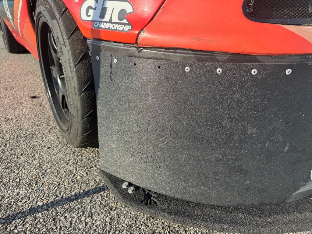
At this point I’ve tested 40-ish car/wing combinations in the wind tunnel, including Pro Car Innovations (55”, 68”), 9 Lives Racing single (55”, 64”, 68”, 72”), and dual wing (64”, 72”), Wing Logic original (70”), APR GTC 250 (61”), S1223 (54×11), 3D MSHD 500 sq-in (63”), GLTC 250 sq-in, lots of my own DIY wings, and a few others that are sworn to secrecy. So getting the MSHD tested and compared against this database of knowledge was important.
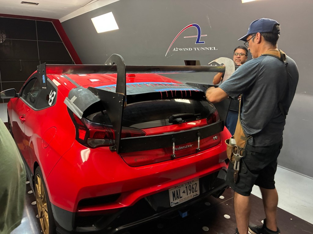
I brought three Wing-Logic MSHD wings for testing: 71”, 68”, and 64”. I tested both bottom mounts and swan necks, and put 10 different endplates on them. The 64” wing is set up to be used as both a single wing and a dual wing so that I could test that as well. I’d put these wings on my Veloster N and a first gen BRZ, and get not only the data, but apples to apples comparison with other wings.
If you’re wondering who pays for these wind tunnel tests, I do. It’s insanely expensive, and the only way I can offset the expense is by taking donations. There are no annoying adds or popups on my site, because you don’t like them either. Please consider buying me a coffee, which supports this and future wind tunnel tests.
MSHD airfoil
MSHD stands for Motor Sports High Downforce and that’s what it was designed for. It has more camber and thickness than airfoils developed for aviation.
Which makes sense. A wing should be designed for a particular application and speed. Cars are not airplanes, and so putting an airplane wing on a car makes about as much sense as putting a car wing on an airplane.
As a motorsports airfoil, the MSHD needed to be useful not only as a rear wing, but also as a front wing (taking advantage of ground effect), and as a dual element. But primarily it needed to work at lower Reynolds numbers, which means lower speeds and smaller wings (less chord).
Someone recently sent me an Instagram reel about the MSHD being only useful for low speeds, since it was developed for FSAE cars, with Reynolds numbers of 300K. Doing your aerodynamic research on social media is eating other people’s vomit, but I’ll address that nonsense right away.
Just because a wing was designed to work at low Reynolds numbers doesn’t mean it won’t also perform well at higher Re. Go to Airfoil tools and look up all the low-Reynolds high-lift wings and notice how they improve in efficiency the faster you go, even up to 2 million Re.
The Wing-Logic MSHD has a 250mm chord, and 300K Re calculates to about 38 mph (61 kph). The A2 wind tunnel operates at 85 mph, which is around 680K Reynolds. So if the MSHD works well at over 225% of its designed speed (it did), rest assured that it will work at whatever speed your car goes (it will).
And finally, if you need a wing for FSAE or autocross, then this is your guy.
MSHD vs 9 Lives and PCI
Probably what most people want to know is, how does the MSHD compare to industry standards, like the 9 Lives Racing Big Wang and Pro Car Innvoations (PCI) wing? So let’s start right off with comparisons. To even the playing field, all of the wings were tested with the same endplates, and not the ones that come in the box.
Note that for all of the data that follows, I use 100 mph as the reference speed. This is lower than many manufacturers use, because people like large numbers. But I feel this is a more realistic speed, at least for my audience.
For simplicity, I measure wing angle from the horizontal. But note that air comes down the rear window at an angle, usually around 5-7 degrees, such that a zero degree setting is actually 5-7 degrees angle of attack. Most wings will stall at over 12 degrees, and so I usually stop at about 5-6 degrees from the horizontal. Obviously the shape of the car, and the location of the wing (height and setback distance), also change the angle of incidence, and unless you know those exactly for every car, measuring from the horizontal is just a heck of a lot easier.
First I tested a 64″ MSHD versus a 64″ 9 Lives Racing Big Wang. This is their original wing, which is now sold as the Express. I put these on my Veloster, which doesn’t work particularly well with wings, so it’s a great worst-case scenario.
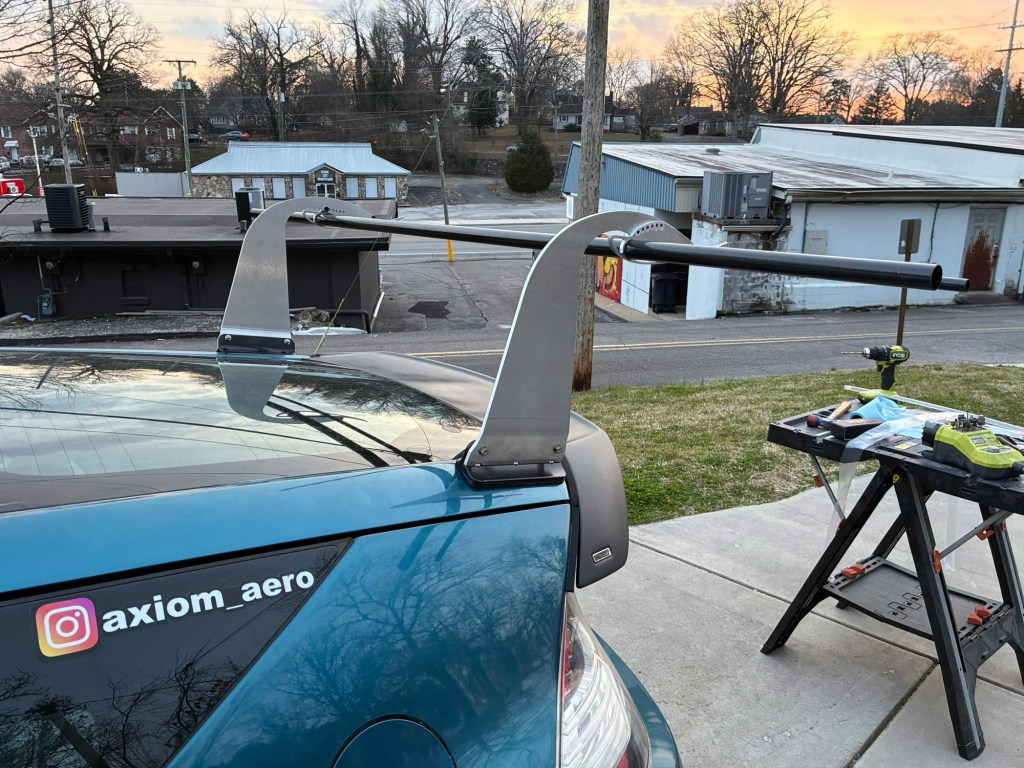
I made a custom roof mount so I could test wings with Miata spaced brackets at various heights and setback distances.
In the following table I list both the L/D ratio of the wing itself, and also the L/D ratio of the entire vehicle. This is an important distinction, because an ultra efficient wing that doesn’t make a lot of downforce won’t influence the overall aerodynamics of the car. It’s far more important to make a lot of downforce, which results in the vehicle having a better L/D. In the end, this is what matters.
Also, if you’ve read my other articles you may have noticed the L/D ratio of the wing is different every time. That’s because the shape of the vehicle has a lot of influence on the performance of the wing. The same wing on my hatchback might be 4:1 L/D, while on a Miata it might be 10:1, and on a 8th gen Civic Si, a magical 25:1. That’s yet another reason why looking at the L/D of the wing is less important, and what really matters is the aerodynamic efficiency of the entire vehicle.
Wing
Downforce
Drag
L/D wing
L/D car
9LR 0-deg
130.9
30.2
4.334
.53
9LR 5-deg
157.6
38.3
4.116
.61
MSHD 0
148.4
37.5
3.961
.58
MSHD 5
191.1
49.2
3.884
.72
MSHD 9
210.5
57.7
3.651
.76
As you can see, the 9 Lives Racing wing is more efficient, in the sense that it has less drag for the downforce that it produces. However, the MSHD makes significantly more downforce, and results in a better L/D ratio of the entire car.
Next I compared a 68” MSHD vs a 68” PCI on Raul’s first gen BRZ/FRS/86. This is a properly shaped fastback and a better test of rear aero.
Wing
Downforce
Drag
L/D wing
L/D car
PCI 0-deg
150.6
21.7
6.95
.57
PCI 6-deg
170.1
25.8
6.60
.7
MSHD 6-deg
191.7
28
6.85
.78
On the BRZ we only ran the MSHD at 6 degrees, to match the high-downforce setting of the PCI wing. Again, you can see the MSHD results in a better L/D of the vehicle, and surprisingly the MSHD wing itself is also more efficient than the PCI at the same 6 degrees.
(If you’re wondering how a 9LR and PCI compare, see my first wind tunnel report, they were quite similar.)
Isn’t this just about more chord?
The Wing-Logic MSHD measures 250mm chord, which is 106.5% more chord than the 9 Lives wing, and 113% more than the PCI. If we just scaled up the 9LR and PCI to the same chord, wouldn’t they perform better, and maybe even beat the MSHD?
Possibly. For sure more chord is better, it means you can a) make the same amount of downforce with less wing angle, and b) wings are more efficient at higher speeds or larger chords (which are essentially the same thing), and so a wing with more chord is more better.
But one thing that sets the MSHD apart from really any other wing I’ve tested is that it can be set to absurd angles of attack. This is why we tried the 9-degree setting, and even at that, the wing wasn’t stalling yet. It’s likely that with a Gurney flap, we could have gone to 12 degrees or more. Which is crazy, because the roofline itself is adding 5-7 degrees to the wing angle.
But that’s one of the great things about the MSHD shape, is that it can use aggressive angles of attack. The wing won’t be especially efficient at high AoA settings, but it does mean you don’t necessarily need a 3D wing.
3D shapes, or twisted wings, are made so that the center of the wing doesn’t stall. This is because the air coming down the middle of the wing is effectively at a greater angle of attack than the air on the sides of the car. Twisting the ends down means the entire wing is at the same angle of attack. However, you can use a 2D MSHD wing and the center still won’t stall, getting much of the benefit of a 3D wing.
MSHD single vs a dual element wing?
Wing-Logic’s Michael Jui wondered out loud how his MSHD would compare to a 9 Lives dual element. I told him that the dual element has more chord and camber, and so there’s no way they can compete against each other. But for shits and grins, I’ll combine a couple data points from the wind tunnel to see how close we can get.
For comparison sake, I’ll use a 9 Lives dual element using standard bottom mounts, with the main wing set to zero degrees and the upper element to 35 degrees. This is about the maximum downforce setting, and very hard to beat.
For the Wing-Logic, I’ll use swan neck wing mounts, a 1/2″ Gurney flap, and set the wing to 5 degrees. (It would have been better to use 9-degrees AoA, but I didn’t run that angle with the Gurney flap, and I don’t want to guess at the values.)
Wing
Downforce lbs
Drag lbs
9 Lives dual, 0/35
284.2
76.4
MSHD swan, 5-deg
250.1
70.8
You can see the MSHD single falls short of the 9 Lives dual element by 34 lbs of downforce, but it also makes less drag. So the 9LR dual element is clearly superior to a MSHD single element for outright downforce, but I’m surprised how close the MSHD got. And I wonder about a higher angle of attack, and using higher downforce endplates (you can read about that in my next article, Time Attack endplates closed the gap to just 18 lbs between MSHD single and 9LR dual).
So the next obvious question is, what about using the MSHD as a dual element?
MSHD dual element
I already wrote up an article on how I built a MSHD dual element, and so click over there if you want the backstory. The upper element is eBay crap I cobbled together, and not a great wing. Nevertheless, the MSHD dual element worked great.
ng
Downforce lbs
Drag lbs
Car L/D
9 Lives dual, 0/35
284.2
76.4
.97
MSHD dual 0/30
314.0
97.0
1.00
MSHD dual 5/35
331.3
111.2
1.01
That’s a lot of downforce, especially in the 5-degree setting, and also a lot of drag. For an autocross or low-speed track, where downforce matters and drag doesn’t, this would be pretty awesome. Michael Jui was so impressed by the results that he’s planning on making a proper MSHD extrusion for the upper element. More on that in the future.
Conclusion
I have no financial relationship with Wing-Logic, but I wish I did. Compared to the original Wing-Logic, the MSHD makes more downforce, even without the built-in Gurney flap of the original wing. The MSHD is also significantly lighter than the original wing, and a better product at the same price.
At the same length, the MSHD makes more downforce than any other aluminum wing I’ve tested. The end result is that a car with a Wing-Logic MSHD will have a higher aerodynamic efficiency than with any other wing. (I’m not including carbon fiber wings with 12+” chord, as that’s a different playing field, and market).
When I graph the downforce and drag of the MSHD at different angles of attack, and then compare the resulting vehicle lift-drag ratio with other wings, it’s clear that the MSHD results in better vehicle efficiency at all angles. Equally important, the MSHD allows you to use a higher angle of attack than any other wing, which obviates the need for a 3D wing. With a swan neck wing mount and a Gurney flap, the MSHD isn’t that far off the maximum setting for a dual wing, although I have to admit I’m looking forward to a proper dual element as well.
I tested a bunch of endplates and Gurney flaps on this wing, and I’ll get around to posting those results sometime soon. I’m also putting the dual-element on a Lancer EvoX for some real-world track testing. But stop reading now and jump over to Wing-Logic. Michael tells me he sold out his last shipment quickly, and I expect the latest batch to go fast as well.
Last week I went to VIR and the A2 wind tunnel. Both are about 10 hours away from me, so I made it a twofer and hit them on the same trip. I couldn’t get two consecutive days at A2, so the wind tunnel testing was on a Monday and a Thursday, with VIR in between.
I’ll get around to sharing some of the data in the upcoming weeks, and follow up with another wind tunnel report. I’ve been talking to AJ Hartman about writing a book together, and I think I think this could take the place of the wind tunnel report, but we shall see.
Monday was slated as hatchback day, with my Veloster and Andrew Rivers’s CRZ. We also had some extra company, with Kaan from the Blind Apex podcast, Michael Jui from Wing-Logic, and Robertson Racing’s aerodynamicist Tim Miller.
Thursday was fastback day. AJ Hartman brought a customer’s C7 Corvette, Raul Iriarte brought his ST5 BRZ, and Pete Mink a Porsche 944. We also had a few more guests with fellow blogger TJ Lathrop from The Rising Edge, and aerodynamicist Ido Waksman, who used to work for Honda and Pratt Miller, but now has his own business called MAD Aerodynamics. AJ also brought along a couple employees, past and present, who hadn’t been to the wind tunnel before.
So it was a full house on both days, and sometimes chaotic. But with plenty of hands on deck, we had extra people to turn wrenches, fetch things, wool tuft the cars, and fabricate parts as needed. All of which is necessary because nothing goes exactly as it should.
I spend a lot of time organizing, building parts, figuring out the order in which to test things, and putting together spreadsheets. This mostly works out, but there’s always a fitment problem, or something you left at home. No plan survives contact with the enemy.
For example, Andrew’s S1223 foam-core wing didn’t make the test. During vacuum bagging the core shifted, and so he got a pretzel instead of a wing. Andrew ordered a Simon McBeath wing, but it wasn’t ready until the day after the wind tunnel test. I thought maybe we could use a new nylon wing from Adam Bao of Epsilon, which was coming hot off the presses from Asia… but it too was stuck in shipping.
In the end, I made up a set of temporary mounts for my 71″ MSHD wing, and I’m glad that worked out, because we got great data from his car.
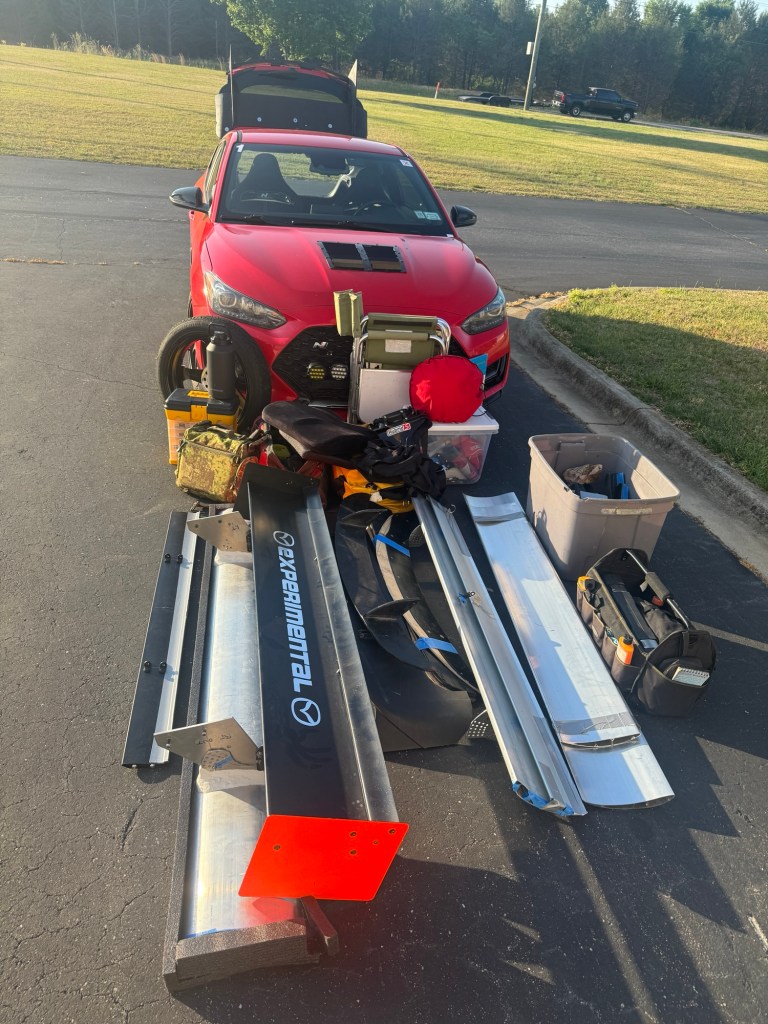
Day one testing
After unloading 8 wings, 4 spoilers, a roof extension, tools, parts, raw materials, etc., the Veloster went first into the tunnel. The first four runs were canard size and edge height, the former being obvious, the latter less so.
No trailer needed, all of this went inside the car.
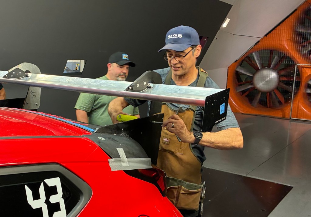
Then I was onto wing mounts and locations. I started with basic mounts below the wing, then also used radiused fillets, which both reduced drag and increased downforce. I ended with reverse swan necks, which oddly increases drag, but also increased downforce a fair amount.
Attaching the reverse swan mounts while Kaan does absolutely nothing.
All of this testing was with a 71” Wing-Logic MSHD. I then tested endplate shapes, sizes, vents, etc., then set the wing aside so that I could do wing comparisons.
I swapped to a 64” version of the MSHD, so I could test it versus a 64” 9 Lives original wing. I tested both as single wings and dual wings, and the MSHD made more downforce, which resulted in higher efficiency for all angles and arrangements.
I’ll do a full write up on the MSHD performance soon, but to sum it up, it outperformed every other aluminum wing I’ve ever tested.
We then switched to Andrew’s CRZ, which put down some of the best numbers I’ve seen, with over 1.6 L/D ratio. This is pretty astonishing since he doesn’t have a splitter (but does have an undertray), and that he borrowed a wing which we riveted on just before the test.
He did some tests on canards, open/closed windows, and a wing sweep. All of this should be quite useful when he gets his new wing, which is of course different, but should give at least some point of reference.
All told I did 31 runs on my Veloster, and 8 on the CRZ, which brings me up to about 70 runs just on hatchbacks, over my various tests. I really should write a book on hatchback aero at some point.
And then I was off to VIR for what was supposed to be a couple days of instructing and driving.
A day at VIR
I was supposed to instruct for two days VIR, but we had more instructors than students and so I had nobody to teach. Which was fine for me, since this was my first time at VIR.
The first session was spoiled by my helmet being soaking wet because the Veloster A/C vent gets clogged easily, and then dumps water into the passenger footwell. I forgot about that, which is where my helmet and DE gear was.
But it was hot at VIR and my gear dried out quickly. I made the second session, which was a “how does Assetto Corsa match up with real life” experience, and it went well enough, except for the number of cars passing me. Everyone was on better tires and had more power, which made me the rolling chicane in the advanced group.
By the next session it was 130 degrees on the asphalt. My “cold” tire temps measured 117 with my pyrometer. I started to pick up the rhythm, but I was slowing too much for South Bend, T14, and Hog Pen.
I did one final session at the end of the days and managed a 2:20. I’m not particularly proud of that, it should have been a 2:14-15 based on the fact that VIR is a couple seconds faster than WGI.
Anyway, it was hot, three sessions wasn’t really enough for me to feel comfortable, my RS4s were toast, and whatever other excuses I can manage. The straights are too long for my tastes, but wow, it’s a fun track. VIR is every bit as good as people say it is.
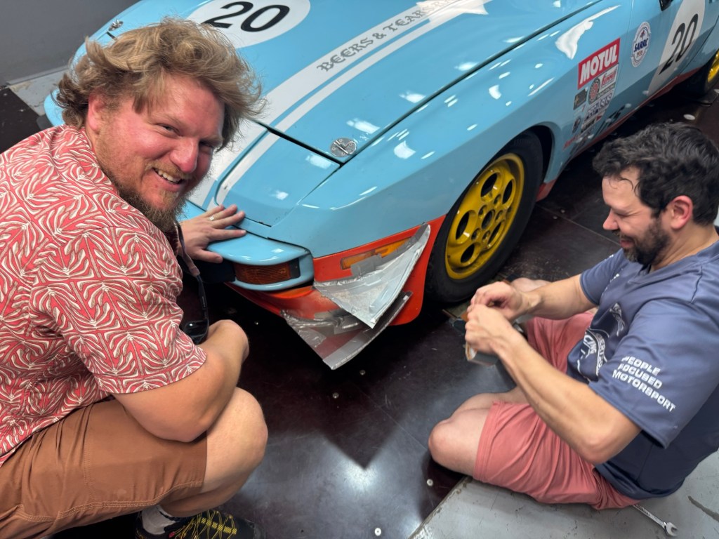
Interlude: Pete’s 944
Getting back to the “no plan survives contact with the enemy” theme, let’s talk about Pete Mink’s Porsche 944 endurance racer. In this case the enemy was his neighbor’s son, who broke into Pete’s garage, stole his racecar, and took it for a joyride! I give the kid props for figuring out the kill switch, but teenagers these days don’t know how to use a manual transmission, so he money-shifted it, locked it up, and crashed into a ditch.
I found out about this midday Tuesday, while I was at VIR. Pete’s truck broke later that same day, and so he was well and truly fucked with no car, no truck, and much to do before the wind tunnel test on Thursday. Talk about kicking a man when he’s down.
So I did what any fellow racer would do and sacrificed a day at the track to help a brother in need. I left VIR at 6am the next morning, drove to Asheville, spent all day with Pete, and got back to my hotel in Mooresville some 14 hours later. A long day surely, but we got the aero installed, fetched his fixed truck, pushed the 944 into the trailer, and called it a day.
The forest rally stage part of the trip going from garage to garage on Pete’s property.
We didn’t get all of the aero transferred over to Pete’s backup car. The front was trashed, and so all the runs were done with no splitter or undertray. The backup car also didn’t have a transmission, so we had to push it in and out of the trailer, and so it was good that Pete is an ex-strongman competitor. He literally used to put on a harness and pull a semi truck from a standstill. This came in handy.
Back to the tunnel
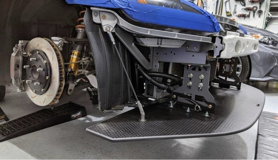
Day two in the tunnel was hectic, with three cars to test. AJ Hartman went first because Raul and Pete were still in transit, but we had planned for that. His customer’s C7 put down some impressive numbers with the 14” chord wing and well developed splitter.
Then it was Pete’s turn, and we did a wing sweep with the new 9 Lives Evo wing. Since his car has no front aero, the balance is way off, but now Pete knows where to set the wing before it stalls.
We also made some DIY canards, using some of the knowledge from my Veloster testing. These worked really well, with almost no loss of rear downforce, and really good gains on the front. The surprising part was an efficiency of nearly 5:1, which you don’t generally see from canards.
We made canards on site. Pete (left) and Raul can’t keep a straight face about it.
Raul was next, and we did some of the coolest stuff on his car. Wing sweep and wing swap (PCI, 9LR, APR GTC200, Wing-Logic MSHD). We even did the 250 sq-in spoiler vs wing (swan neck this time) test for GLTC free points.
Raul got some great results out of splitter test, with both splitter angle and tunnels being evaluated.
I will say, the fastback shape of the BRZ makes it tricky to get the aero balance correct. The sleek shape means the rear has a ton of lift with no rear aero, but also makes a lot of downforce with a wing. And so the front/rear balance shifts more on this car than any other car I’ve seen.
You can’t just throw parts on a car like this and know what you’re getting, you have to test it. The car on the first turn, with a splitter and wing, had 0% front aero load distribution, but by the end of the test, was hitting the right numbers.
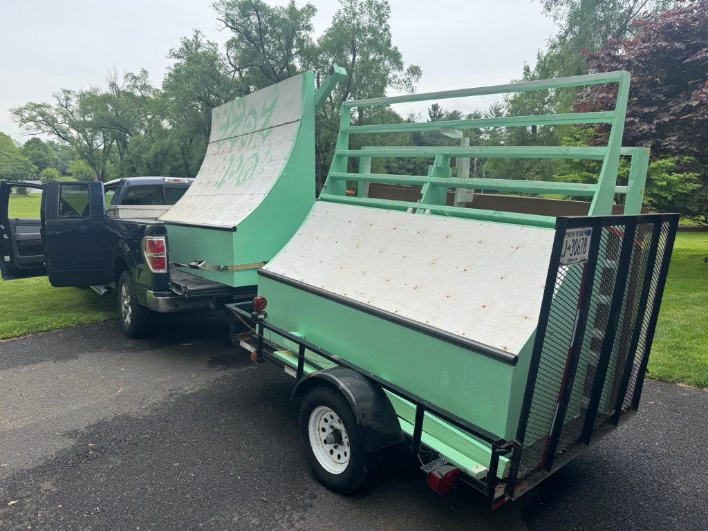
After that it was load up all the gear again, and drive the 10 hours back home, with a stop at Phil’s house to drop off the 9 Lives dual element I borrowed. I was back at Phil’s a couple days later to pick up some skateboard ramps his son Andy made. They generously gave these to me, and so thank you wind tunnel community, lets keep growing and sharing.
New skateboard ramps for me! From the team that has the Miata I took to the wind tunnel.
This site recently hit half a million views, and that milestone seems like a good time to reflect on how this all began.
I started this website in January 2019, with the intention of filling gaps in the Miata aerodynamics knowledge base, such as roofline shape (fastback vs OEM vs open top, etc.). I also wanted to make it easier to find information on Miata aerodynamics in general. There’s a lot of great information strewn about online, but it’s mixed up with things that are misleading or outright wrong (ahem, CFD). My intention was to put all the good stuff in one place, and keep adding to it.
Seven years later, my own site is becoming difficult to navigate. I’ve polluted all the good Miata information with tire tests, waded into articles on performance driving, mixed that in with a silly hatchback, and have even used this website as a goddamn diary. Now I have the same navigation problems I was trying to solve! So I thought an annotated list of my best articles could prove useful.
But it also occurred to me that recycling old content is anything but original. It’s like when a band releases a Greatest Hits album… is there a clearer sign that the band has hit the end of their career than recycling old songs on a new album? Well I guess there is something worse, they could start writing songs about Rock and Roll.
Songs about Rocking are the death knell of writer’s block. Whether it’s I Wanna Rock, or Rockin in the USA, or the worst song of all time, We Built this City (on Rock and Roll), writing about rocking is the opposite of rocking. It’s sucking.
So here we go. Here’s my Greatest Hits of the Occam’s Racer website, and I hope it Rocks Out!
Top five hits
The top five songs articles in terms of traffic are:
Car Wing Comparisons – I investigate different wings you see on cars, with some low-Reynolds, high-lift standouts like the MSHD, S1223, etc.
How to Calculate Wing Downforce – I would never use such a simple formula to estimate downforce, but apparently other people use this a lot.
Spoiler vs Wing – Wings get a lot of attention, but spoilers don’t reduce front downforce the way wings do, and so spoilers are actually better for cars without a splitter.
These are slightly less popular, but are referenced a lot.
The Dunning-Kruger of Car Aerodynamics – We all start our aero journey without knowing what we’re doing, but with all the confidence in the world. Eventually that flip flops and we find ourselves in the pit of despair. And then we crawl out.
Active Aero Wings and Spoilers – Wherein I run simulations in OptimumLap and discover that DRS isn’t that useful on single-element wings and spoilers.
GT7 Aerodynamics – A self-indulgent nerd article on the non-realistic aerodynamics in Gran Turismo 7 results in some pretty cool discoveries, like the speed they use for downforce values, and the aero balance of all the cars.
Performance driving
My identical twin brother has a website, You Suck at Racing, which is largely about performance driving. So I don’t delve into this topic much, but I have written a few articles on the subject.
Understeer is Faster than Oversteer – Proof that forcing an understeering car to oversteer on corner entry is faster than catching a car that wants to oversteer everywhere.
Twin studies – My identical twin brother and I have opposite driving styles, and yet we’re both very fast. Lots of data here.
These aren’t listed anywhere on this website, but I’ve been on a few podcasts. Some of these are Spotify links, or Apple, or whatever. I don’t manage them, so don’t kill the messenger.
Aero for Endurance Racing – I try to use the Socratic method with Bill and Vicki, but I get blindsided by questions. This is a good one, though.
Miata Aero – I go on the Blind Apex podcast to talk about wind tunnel tests on a Miata, and how they don’t match the CFD. But we get into some other great results.
Visualizing Airflow for 2D and 3D Wings – I put a GoPro on the side of my car and capture video of cardboard telltales at various positions. This is how you figure out the angle of incidence on the rear wing. Good stuff.
Miata Wind Tunnel Report – I take a Miata dressed up in full 9 Lives catalog, and get very different results in the wind tunnel than they got in CFD. Lots of other very cool stuff tested.
Miatas, but not aerodynamics
I’ve written a couple good articles on Miatas that aren’t just about aero.
Miata Suspension Calculator – Wherein I use Fat Cat’s calculator to examine different combinations of springs and sway bars, and how that affects front roll couple (understeer vs oversteer).
Tuning a 1.6 Miata – A modern take on the solomiata.com formula. After two previous articles on why I wasn’t going to do a 1.8 swap (part 1 and part 2), I go deep into the weeds squeezing the last performance from a NA 1.6. The punchline is that I’m currently in the middle of a 1.8 swap. However, back when it was a 1.6, there was that one time it beat up a KMiata and took its lunch money.
Making Lemonade from 24 Hours of Lemons – Pre-race preparation fails, a DIY shooting brake, shitting all over myself (literally), and then the fine taste of sour grapes, this article has it all.
Veloster N aerodynamics
Hatchback’s have shitty aero, but I keep polishing this turd.
How Much Downforce Do Canards Make? – I test the exact same canards in three different locations and get anywhere from 9 lbs to 81 lbs of downforce. Astonishing.
Testing Spoilers and Wings on a FWD Hatchback – This is a must-read for people who believe aero balance should match chassis balance. What’s surprising is that the car goes faster with more rear downforce and no front downforce. I then do the same test at NYST, and the results are even more dramatic, -2.5 seconds per lap only with rear aero. I then try a similar test at Watkins Glen.
Veloster N Splitters – Kinda everything on the subject, including aftermarket products, DIY build, and wind tunnel results.
Testing Wing Endplates – I test a bunch of endplates and find out that the 9LR CFD endplate works the same forward and backwards, and that the best of the test is a street sign cut in half.
Diffusers Without Flat Bottoms – The A2 wind tunnel isn’t the ideal place to test underbody aero, but I do it anyway, and come away unimpressed.
Veloster N, but not aerodynamics
More words on the best car I’ve owned.
Long-term Track Report – I recap a couple years of ownership, and why I bought the same car twice.
Tow Hitch – There’s no tow hitch available for the N, so I modified the tow hitch for a base model Veloster. Twice.
Mando ECS10 for Veloster N – How to install and configure the Mando suspension controller for your Veloster N or Kona N.
Hood Vents and Cooling – I test engine temperature using 50/50 anti-freeze versus Water Wetter and also hood vents. I later did an article where I installed Race Louvers.
Engine Modes Dynoed – I take my car to the dyno and get 244 hp at the wheels. And then I test the different engine modes and find out it’s basically the same in every mode.
DIY
I build a lot of my own aero parts, so it was hard to cull this list to just five.
MSHD GLTC 500 – I build a foam and fiberglass wing with a MSHD profile, 3D shape, and 500 square inch limit. I test it in the wind tunnel and beats all the other wings.
DIY Selig S1223 – I build a low-Reynolds high-lift wing the old-fashioned way.
Miata Opera Coupe – This is the stupidest DIY project I ever did, giving my Miata the “She’s my sister and my daughter” look of an opera coupe.
Gas Can Speed Test – I try different ways to dump 5 gallons of fuel as quickly as possible.
Cold-side Ram Intake – I make a ram-air cowl induction system that is so loud I have to remove it. In keeping with the DIY theme, I make a manometer out of a soda bottle and yard stick.
Tire Tests
I have hundreds of laps at Pineview Run, and can consistently put a car on the limit. I feel like this makes my tire tests pretty decent.
Is the Blu Trac Race the Best HPDE Tire? – This is a 400TW tire with a 200TW label. Nevertheless, I conclude that the all-season grip level and predictability make this a great learning tire.
My race reports are long and narcissistic, and belong in a worst-of Occam’s Racer. Skip these.
Beating up Miatas in a Yaris – We race Thunderhill backwards in a 100-hp FWD hatchback and beat 10 out of 12 Miatas.
Everturrible: I race a Honda minivan at Thompson, Thunderbolt, and PittRace. This was my last and best race in it, in which I also used Accelera 651 Sport tires.
Mid Ohio Part 5. Driver-mod coach and Supermiata driver Sonny Watanasirsuk joins the Occam’s Racer team for an enduro at Mid-O. Alyssa, who had never driven the track before, beats Sonny in every session.
Sebring Race Report – I drive a first-gen MR2 in the rain, beat the team’s best lap by 10 seconds, break the car, and kill a wild boar.
Snark
Because aerodynamics is a math-heavy, nerdy subject, I try to be both informative and amusing at the same time. Sometimes I have fun at someone else’s expense, but it’s meant in jest, not to harm.
Who am I kidding? Sometimes I’m out to hurt feelings. I mean, that’s why I drive a fucking Miata. It’s underpowered, a disrespected hair-dresser car. So when I pass a GT4 Clubsport on the outside, and they park it in the next session… bitch, that’s winning.
So here are a few of my most insulting articles.
The Dumbest Aero Rules? Splitter Rules – I bash everyone who regulates that splitters must be flat and horizontal. And I bash Lee Childs for conflating a M1 Garand and a M14.
Autocross N00b: In which I try to class my Miata to a fecking ridiculous set of rules, drive poorly, and realize I have Lyme disease. Again.
The Aerodynamics of Open Windows – This is actually a really useful article, but I never turn down the chance to poke fun at a Porsche owner bringing a Cup Car to a DE.
I’ve been itching to use a smoke wand for some time, but whenever I go to the A2 wind tunnel, I never use it. Smoke doesn’t return any numbers, and it takes time, and time is money. So being a cheap bastard, I use short yarn tufts to visualize what’s happening in the boundary layer, and call that good enough.
But yarn isn’t great for scratching the smoke wand itch, so when I saw a prototype scale model wind tunnel a couple years ago, I got on kickstarter and became an early backer of Windsible.
As a backer, I got regular progress reports and saw the development process evolve. It’s a shit ton of work! From my initial backing to delivery took 22 months.
The unit required very little assembly, and the quick start instructions got me up and running within minutes of unboxing. The machine was already set to my preferred language and to mph, which was a nice touch.
It also comes with cleaning tools, an extra filter, and two bottles of fog fluid. There are two fog dispensers, one vertical and one horizontal. They attach magnetically to the fogger base, so there no futzing around with small parts. Very clever. You can also buy more fogger attachments from Fun-Tech-Lab.
You can adjust the color and brightness of the internal lighting, but most of the illumination is at the front of the tunnel, and I’m more interested in what happens at the trailing edge. Anyway, this works well in a dark room, and not as well with lights behind you (glare).
For build quality, design, and ease of use, I’m giving this a solid 10 out of 10.
Scale models
The Windsible is designed for 1/18 cars, and the fan speed scales up to 210 mph in that size. You can of course put any size cars in the wind tunnel, and I think 1/18 is actually too big. 1/24 scale cars are cheaper, and the smaller size lets me see more of the trailing wake.
My local CVS pharmacy has a bunch of 1/24 scale cars and I got a Celia GT and C6 Corvette there. I would have bought more cars, but many were missing mirrors or other small parts. Alibaba and eBay are both good sources for 1/24 diecast cars, and many plastic Tamiya models are also in this size.
Lowe’s has a bunch of smaller scale vehicles for just $7. These range from 1/28 scale to 1/36. Most of the cars are 1/32, but there are some oddball sizes mixed in, such as 1/31 and 1/33.
I can see a problem developing already….
I bought a Subaru rally car at 1/36 scale, and it’s borderline too small. The problem isn’t just the size of car and its parts, but the height of the streamlines. It’s necessary to raise the cars up slightly to get into the bottom stream.
1:36 scale WRX STi. When pointed straight ahead, the low and short rally wing is entirely in the wake behind the canopy. When the car is in yaw, the wing and strakes come into play.
The only Veloster N I could find is in 1/38 scale, which is too small to develop parts for. I’ll use this one to mock up interactions with a teardrop trailer I’m building, but for visualizing aero parts, I’ll need something larger.
I plan to do a whole series of tests and videos, but I need a repeatable way to set up cars exactly the same way, a static camera mount, and lots of little parts.
Open windows
I can tell you one thing right away, which is that every car is different with respect to open windows. Some cars seem to be designed for open windows, with mirror placement and other factors actively shunting air away from the window.
1/24 Celica GT seems quite good with open windows.
On other cars, air smashes into the B-pillar and creates turbulence inside the cockpit. This results in a vortex of air shooting out the top rear edge of the window.
C6 appears much worse with open windows. I like spoilers, and will test them at various heights on lots of cars.
How open windows affects aero is a fascinating subject, and an area I will spend some time investigating. This is something I’ve already experimented with in the A2 wind tunnel, and so I’m not surprised every car is different.
If you’ve read my first wind tunnel report, you know that open windows reduced rear downforce by 15% and increased drag by 7% on my Veloster. I was able to halve these with rain visors.
Meanwhile the Miata I tested in the second wind tunnel report did not lose as much with open windows. But I was still able to reduce drag and increase downforce meaningfully with some clever tricks. (Also, don’t remove side mirrors on an open-window car.)
Finally, Kaan’s 8th gen Civic Si didn’t seem to care one way or the other if the windows were open, or if we put on a safety net, etc. Weird, and wonderful, these differences in just open windows!
Not for drag and downforce
Measuring drag and downforce in a wind tunnel of this size is a waste of time. Anything you’d learn from such an exercise would be just as likely to send you down the wrong path as the right one.
This isn’t a problem of not having an accurate scale (I have scales that go down to a thousandth of a gram), nor the usual things people say about the A2 wind tunnel, like like the wheels don’t spin, or the growing boundary layer, or the blockage ratio from the size of the tunnel. The reason you can’t use the Windsible for drag and downforce is that things behave differently at different Reynolds numbers.
As an example, let’s take an aero modification everyone is familiar with, the dimples on golf balls. The dimples create a thicker boundary layer just before the air separates off the back half of the ball. This thicker area of turbulence delays separation, which essentially fools the air into thinking the ball is more egg shaped, than sphere shaped. An egg is more elongated and has better aerodynamics, and so the ball flies further.
Now what’s truly interesting is that at high speed, the dimples increase drag. Also at low speed, the dimples increase drag. But in the range of speed at which golf balls travel most of their distance, the dimples decrease drag.
Testing a scale model golf ball in this wind tunnel would be folly, because you can’t accelerate the air to a speed where the dimples would reduce drag. It would always show that dimples increase drag. Which we know isn’t true.
Likewise, a scale model wing would be something like 5k Reynolds in this tunnel. In Airfoil Tools, you can’t even enter values under 50k Re! Whereas a typical car wing in a typical corner is going to have a Reynolds number of around 500k.
So any downforce data you’d get from testing at this size and speed (Reynolds number) would not relate to the real world. Total. Waste. Of. Time.
Future testing
So I won’t be testing downforce, but you can expect to see more posts on visualizing flow, including wing placement, yaw, drafting, trailering, and lots of silly aero mods. I’ll title these posts “Windsible # x:” so you can find them or ignore them.
This is definitely more of a winter doldrums kind of toy, and with track season now fully underway, I have full size parts to build and test. So don’t expect a lot of Windsible posts just yet, but they will figure into a Lancer Evo project I’m working on right now.
If you want to join in the fun, but don’t want to invest in a Windsible, I can help. Get a 1/24-ish scale model of your car, preferably in a dark color that contrasts well with the smoke. Optionally modify it to look like your piece of shit Lemons car (or whatever), and send it to Mario Korf, 137 Hopkins Rd, Ithaca NY 14850. I’ll be happy to take videos and pictures with things you want to try. Pay for postage, and I’ll send it back when we’re done.
My annual trip to the wind tunnel is coming up soon. I had originally planned to do just a single day of testing, but two cars became three, which became four. Now I’m at five. And that’s too many to test in one day.
So I’ll be headed to A2 on 5/18 for hatchback day, then to VIR to instruct for a couple days, and then back to A2 on 5/21 for fastback day. There’s room for a third car on the first day, contact me if you want to get in on this.
Hatchbacks 5/18
The first day will be my Veloster N and Andrew Rivers’ Honda CRZ. We are both testing canards and wings, and some other odds and ends.
I’ve tested canards on my Veloster twice now. The first time I was mostly concerned about the location of the canard. If you bought Wind Tunnel Report 01, then you know that location played an enormous role in downforce. The same exact canard produced anywhere from 11 lbs to 80 lbs of downforce depending on how high I mounted it.
The second time I tested canards I wanted to find out if I was getting downforce from the interaction between the canard and splitter, or was it just the canard itself? I was also able to test a CFD-designed canard from Verus, which didn’t produce a lot of downforce, but also had zero drag.
This time I’m testing canard edge treatment and size. The DIY canards I’ve tested on my Veloster have had a sharp outer edge, but I often see canards with a vertical outer edge, kind of a fence or Gurney flap. So I’m testing two different heights versus a plain edge. Then I’ll also increase the size of the canard to see if more area produces more downforce.
Finally, I want to see if I can get a mid-height canard to interact with the lower canard. On other cars I’ve tested, the lower canard does most of the work, while the mid-height canard seems to reduce the drag of the entire system. I want to see if I can make that happen on my car.
Andrew is doing some different canard experiments, seeing if there’s interaction between various front end components. I don’t want to say too much on this, as those are his tests, but they should be super cool.
Next we are both testing wings. I’m finally getting around to testing a MSHD wing, both as a single and dual element. I’ll bring along a 9 Lives with me as well, since that’s a popular benchmark, and easy to test as a single or dual element.
Because hatchbacks are weird, I also plan to test wing location. I’m fairly certain that higher is better, but I want to check forward and rearward locations, and how those affect front downforce. I also want to test bottom mounts versus swan necks.
Andrew is testing a Simon MacBeath wing with swan necks, and I’m very excited to see how that performs. He’s doing a sweep of angles and a couple different end plates. I plan to throw a MSHD on his car, just to see how they compare.
Andrew’s car looks great with all the aero, and I’m interested to see which hatchback will have better numbers. But no matter how it turns out, we’ll learn from each other’s experiments, and both of our cars can improve from that.
Andrew’s CRZ has very nice swan necks. The tube is a stiffener inside his DIY S1223.
Fastbacks 5/21
This is going to be an exciting day, because we can test wings on proper rooflines, not crappy hatchbacks. Pete is bringing his endurance racing 944, Raul has a BRZ, and AJ is bringing a C7.
As part of the wing tests, we will throw a mess of different end plates on the Porsche. I made an Open Call for testing end plates, but so far not that many manufacturers have joined the game.
Just the same, there are some really cool endplate designs we’ll be testing, with vents, 3D shapes, and other trickery. Even if endplates don’t make a huge difference, they are easy to change out and are visually interesting.
We may try the most radical end plates on two or three different cars, to see if there’s any difference. It’s worth checking out, but I kinda doubt it.
Raul’s BRZ will be the test bed for a few different wings including a PCI, MSHD, APR GTC200, and 9 Lives. I’m also trying to get my hands on a Verus high efficiency wing, and there’s a new nylon wing from Baero that might sneak into the tests if it can get through customs quickly. It has a familiar look, but with a lot more chord, and I have high expectations.
We have to fit many of those wings on the same trunk mounts, which is proving to be a bit of work making brackets. We also want to test wing location, and if setting the wing back a little further is better.
Raul doing the obligatory “is is strong enough?” test.
Raul’s car also has a splitter and so we plan to test splitter tunnels and some other front end stuff.
I’ll write up a report this summer, and probably jump on a podcast to talk about some of the results. Hopefully Kaan from the Blind Apex will come down to see some of testing firsthand, and we can recap that on his show with some special guests.
As usual I’m planning to rope AJ Hartman into participating, but also inviting Ido Waksman and Tim Miller, if their busy schedules permit. Michael Jui from Wing-Logic is also coming for the first day, and so it will be cool to finally meet him in person.
All said, it looks to be quite the party, and we are set to learn a whole bunch about our expectations, and that aero results are often not what you think. Subscribe to the blog if you haven’t already, you don’t want to miss the articles coming out of these tests!
This weekend I was instructing at the Mass Tuning event at Watkins Glen. I saw three cars with Racebred splitters. All of them had their splitters mounted upside down.
What do I mean, aren’t splitters just flat? Sometimes and unfortunately yes, but even when they are flat, a splitter behaves essentially as a wing; there’s high pressure on top, and low pressure beneath, and the difference creates downforce. The low pressure undersides of wings and splitters produce much more downforce than the high pressure top sides, and so flow attachment beneath these components is critical.
Racebred only rounds the leading edge on one side of the splitter, and that’s where they put their logo. So people think that’s which way the splitter goes, logo side up. But the underside of the splitter is what matters, so it’s the bottom of the leading edge that needs rounding!
When manufacturers don’t understand fundamentals.
I mentioned this to one guy and he said, “but the texture is on the top side.” Waitaminute. You think putting texture on the blade is a performance enhancement… on the pressure side? The pressure side is of little consequence; any modifications you’d do to reduce flow separation (texture, whatnot), would be under splitter, not on top of it!
It’s understandable that customers don’t know the fundamentals of aerodynamics; it’s not their job. Their job is to buy things. They trust manufacturers to have done the research and give them the products to go faster. So it’s a shame when aerodynamics manufacturers literally don’t know which side is up.
Look, I don’t want to just pick on Racebred. Putting your logo on the wrong side of your splitter is endemic in the aerodynamics manufacturers community. Look around and you’ll see lots of manufacturers who round the wrong side of the splitter blade.
9 Lives Racing splitter has the logo on the wrong side as well.
And when they do round it, it’s like just breaking the edge a little bit. The leading edge of the splitter should be as thick as possible, with as much radius as possible. On the underside of the splitter. This is one reason an Alumalite splitter screams “Amateur!” But I digress.
If you have an aftermarket splitter, do yourself a favor and examine which side the rounding is on. In most cases you’ll want to flip that embarrassment upside down. If the splitter isn’t rounded on either side, round the heck out of the underside leading edge.
At this event, and really at every event, I see a lot of splitters with unused real estate on the outside edge. This does nothing, because it doesn’t change the direction of air. All you’re doing with this extra width is inviting contact with hard objects.
Use this area. (Yes, this is another Racebred splitter mounted upside down.)
A small kicker here is an easy way to increase the pressure differential above and below the splitter. Or put a fence on it and reduce downstream losses. But do something with this extra width people!
These and other mistakes are in my Your Splitter Sucks article. If the manufacturers can’t get it right, at least you have the information to fix it.
This is what a proper splitter blade looks like: Thick leading edge, rounded on the underside, curvature to the trailing edge, and optionally some vortex strakes to reduce tire squirt. (Two versions I built for a E30 with 12- and 5-degree curves.)
A few years ago I tested end plates in the A2 wind tunnel. The data shows that there wasn’t much difference between them, and I may have drawn some hasty conclusions about that.
The fact is, a hatchback with a 55” wing is not the ideal playing field for this type of competition. The combination of a short wingspan and an odd C-pillar vortex coming off the hatchack roof may have polluted the air right next to the end plate. So this really needs to be tested again on a proper coupe or fastback.
I’m going to the wind tunnel on 5/18 and 5/21 with two good candidates, a BRZ and a 944. We’ll be using a much wider 68” wing, and will test end plates for realz this time. (Also, I may have space for one more car, contact me if you are interested.)
So here’s an open call to everyone who makes an end plate for a 9 Lives original (now Express) wing with 4 holes on the end. Send me your end plates and pay for return shipping, and I’ll send them back after the test. I’ll publish the report and send you a copy for free.
I don’t want to leave anyone out. So if you don’t make an end plate specifically for this wing, but you want to be included, I can drill and mount your end plates accurately, to your specifications.
This site is primarily about aerodynamics, but I stray into tire tests, performance driving, and other topics. Over the years the website has become less organized with its broader focus, but it’s still essentially an educational outlet.
I spent my professional career in technical writing and curriculum development, and I consider myself an educator. Good educators are forever-students. We have open minds, and find teachers, and teaching moments, in the least likely places.
Like in a tiny dog.
Growing up I always wanted a dog, but I didn’t have one of my own until a dozen years ago. I had always imagined a short-haired medium-sized dog with a good nose, and a love of the chase. We’d be hunting partners. He’d flush and retrieve birds, or find deer I’d shot with my bow. We’d bond over blood, like the original dogs and men.
What I got was a miniature Schnauzer. He turned out to be she. Small, gentle, fragile, and scared of loud noises, she wasn’t going to be much of a hunter.
But she loved seeing deer. She would bark four times and get herself so excited that her voice would break on the second syllable. Her bark would go Roh-Ri-Roh-Roh. But she’d only do that bark for deer. Later, anytime I’d see a deer I’d go “Roh-Ri-Roh-Roh” and she’d stop whatever she was doing and frantically look for deer.
She had some hunting instincts, but used her eyes more than her nose. This got her a couple squirrels, and amazingly one rabbit, in the middle of the night. I fed her seared kidneys at 2am and she picked up another nickname: Tiny Wolf.
I don’t do yoga, but sometimes we did doga.
Pepper was a nervous traveler, didn’t like cars, motorcycles, or hunting implements, and I can’t say she took to any of my hobbies. But it’s the routines that bind us. That find us.
In the morning, she’d wait at the top of the stairs for me, so we could start our day together. Then she’d sit in the window, and suddenly sprint out the doggie door to bark at passersby. She took this job very seriously, and she was an excellent watchdog.
At night, she’d sleep at the foot of the bed. And when she was sure I was sleeping deeply, move up and cuddle next to me, pushing her bodyweight into mine.
She was a different dog than I ever imagined owning. I ended up finding what I needed in a place I never would have thought to look.
This tiny dog with a huge heart melted mine. But that heart was medically too large. I forget the name of it, but it’s a chronic medical condition; her heart would eventually grow too large and take up her chest cavity, making it impossible to breathe. This bundle of joy had a time bomb for a ticker, and I knew it was going to absolutely level me when it went off.
Up to this point she subsisted entirely on kibble, never had people food, nor begged at the table. But since she was on borrowed time, I endeavored to spoil her. And transformed an obedient pet into an entitled princess. Anytime I was in the kitchen she’d trot in with expectant eyes. Or make sounds that could not be misinterpreted as “where’s mine?”
Methinks the daily charcuterie boards were a little over the top.
Bark-u-terie.
The meds held her heart in check for years, but recently Pepper began having trouble breathing. Last weekend we took her to the ER at Cornell, where she spent the night in an oxygen tent. The vet got the fluid out of her lungs and said she had made a good recovery, and we could still expect more time with her.
But it didn’t work out that way. Pepper went downhill fast and never recovered. She passed peacefully with a final meal, a bedtime story, cuddles, and an injection. I petted her one last time, blubbering in sadness and madness.
I’m no stranger to loss. I’m also no good at it. My son Zack died of an overdose in 2020.
I can’t think about him without crying. I had to move all photos of him on my phone into a private album so that I don’t see them. I’ve never opened a condolence letter. I haven’t had a service or even looked at his ashes. I haven’t moved on. I’m holding onto the pain because that’s all I have left of him. I won’t lose that, too.
So I had always imagined that losing Pepper would incapacitate me. I’d be a wreck for a week or a month or for however long. I’d feel around for her in the middle of the night. I’d wait for her waiting for me at the top of the stairs. But that hasn’t happened.
Pepper had one final lesson for me. It’s about keeping the love with the loss. It’s about cherishing the time we had, rather than the time that was cheated away from us. One fifth of my life I shared with her. And her entire life with mine. It was a blessing, and I’m fortunate.
I don’t understand this entirely, so I can’t explain it very well. But I haven’t cried. I’m not incapacitated. I feel Pepper with me as a strength.
With that support, I know I can finally say goodbye to Zack. To put both of their ashes up on the mantle. To look at photographs, to remember, to love, and to move on.