In this article I take a deep dive into endplates: why we use them, various design considerations, and then testing different endplates in a wind tunnel. I asked several endplate manufacturers to play ball. Some declined, some ignored, but I was able to secure a good batch for testing, and then borrowed or made what I couldn’t acquire. Across my various trips to the wind tunnel, I’ve now tested over 20 endplates, and this article is the first time I’ve put all that data into one place.
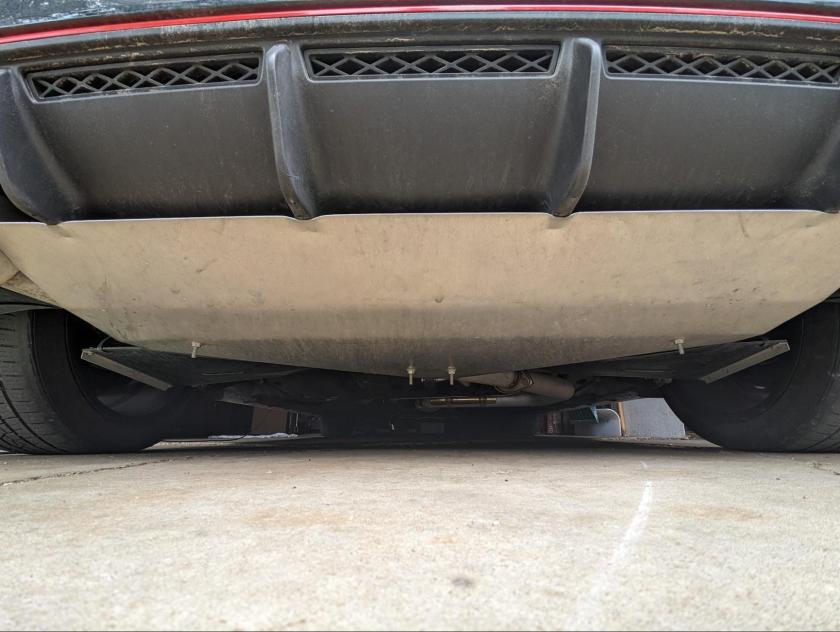
Because these tests cover a few trips to the wind tunnel, I’ll list details about the car and wing each endplate was used on. I always use a standard 12×9 endplate as the basis for the comparisons, and I try to be as scientific as possible.
There’s a lot to cover, let’s get started.
- Wings need endplates
- You won’t read this in a magazine
- Endplates by the inch
- 144 square-inch shapes
- Aviation-inspired experiments
- CFD-designed endplates
- 9 Lives Racing endplates
- Yeti Racecraft endplates
- Miscellaneous endplates
- Conclusions
- Side force and center of pressure
Wings need endplates
Endplates improve a wing’s performance, but there are other reasons we use them.
- Wing performance – According to Simon McBeath (Competition Car Downforce), wings without endplates lose up to 30% of their performance.
- Stability – Moving the center of pressure rearwards makes the car more stable.
- Structure – Endplates can be incorporated into the structure of the wing itself, and in a dual-element wing, provide the mounting points and adjustments for the upper wing.
- Gamesmanship – Endplates hide the airfoil shape; it’s always good to keep your competitors guessing. Fancy endplates also distract competitors from more important things on your car.
- Personalization – Endplates look cool, which is a minor point for some, but the entire point of aero, for others.
In this article I’m mostly concerned with point 1, and to a lesser extent point 2. So let’s jump directly into how endplates affect car performance.
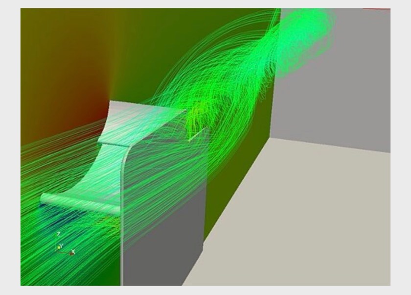
Wings create downforce via the pressure differential between the upper and lower surfaces. At the wing tips, that pressure differential creates a vortex as the car moves forward, because the high-pressure top side wants to move around to the low-pressure bottom side.
Endplates provide a physical barrier, holding the air at the ends of the wing, rather than letting it spill over the sides. This fools the air into thinking the wing is longer (a higher aspect ratio). Larger endplates are better at blocking the air, and theoretically should provide better performance.
You can calculate the benefit of a simple rectangular endplate on a 2D wing using the formula AR = AR_actual (1 + (1.9 * h/b)). Mathematically, this means that aspect ratio (AR) is proportionate to the size of the endplate, or in plainer terms, the larger the endplate, the more it reduces drag and increases downforce.
In reality, I haven’t found that the math works out. In the wind tunnel, changing the size of a rectangular endplate doesn’t get me both drag reduction and more downforce, I get more of both or less of both.
That math formula is for rectangles, and rectangles are boring. Endplates can, and should, be sized and shaped to a specific airfoil. Every airfoil has a different shape and area of its high- and low-pressure regions, and most motorsports wings have a low pressure zone that extends very low and in front of the wing.
As you probably know, the low pressure side is much more important than the high pressure side. Wings make about 70% of their downforce from suction, and so it’s the underside of a car wing that matters the most. This is why endplates extend further below the wing than they do on top, and it follows that deeper endplates should make more downforce.
To gain even more downforce, you can add a small Gurney flap to the trailing edge of the endplate, to kick air sideways. This makes the wing seem like it has more span. You can also bend the endplate such that some air is deflected upwards, which creates downforce.
In addition to the size, shape, and bends on the endplate, you can add vents. Vents are usually in the form of slits or notches cut in the top of the endplate, or at the trailing edge. Although sometimes you see vents on the bottom of the endplate, mixing outside air into the wake. Regardless of where they are, the point of venting is to bleed some of the high pressure air to the low pressure side. This may seem counterintuitive, because lowering the pressure differential reduces downforce. But, if done cleverly, venting can reduce the wingtip vortex, and thereby reduce drag, while not losing too much downforce in the process.
In a nutshell, or perhaps a better idiom is, in this shell game, that’s what endplate design is: trying to get something for nothing. Either you’re trying to get drag reduction without losing downforce, or trying to get downforce without increasing drag.
So how do these different shapes and sizes combine with cuts, vents, Gurney flaps, and bends? Well, that’s what we’re here to find out. Before we dive into it, here are a few things to keep in mind:
- All values are listed at 100 mph. The A2 wind tunnel operates at 85 mph, but I use 100 mph as a standard convention (as does Simon McBeath, AJ Hartman, and other people smarter than me).
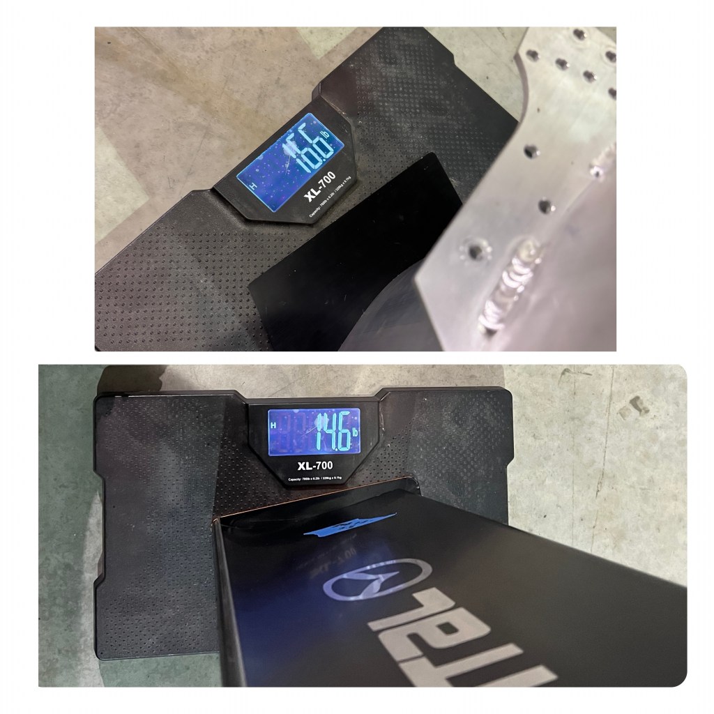
- A gallon of gas is about 6.2 lbs, and so if you see an endplate that makes that much additional downforce, an extra gallon of gas in the tank is about the same amount of additional grip.
- One horsepower is about 7 lbs of drag (on the cars I measured here), and so an endplate that reduces drag by say 3.6 lbs gained about .5 hp at 100 mph, which is negligible.
You won’t read this in a magazine
I think I’m the first person to publish an exhaustive endplate test with wind tunnel data. It begs the question, why me? Or rather, why haven’t I read about this already in a magazine? Car magazines will dyno test different air filters, intakes, exhausts, motor oils, etc. They’ll rent track time to test a new 200TW tire as soon as it comes out. But aero testing? Notsomuch.
But people also want to know about aero, and one of the most intriguing items has got to be endplates! They are cheap, easy to install, and come in a variety of shapes and sizes. Most endplates are “CFD designed” and if we believe the wild (and unsubstantiated) claims of increased downforce and/or drag reduction, they are a great bang for the buck. Which is best?
I can’t say for sure why car magazines won’t test things like this, but it seems like a combination of the following:
- Lack of interest – If you search the archives in GRM, Road & Track, or any other rag outside of Racecar Engineering (which stands head and shoulders above everything else in this regard), you’ll see precious few articles on aerodynamics. I can count them on one hand.
- Conflict of interest – Manufacturers place ads in magazines, which puts food on the table. Comparative test only works out for the winner. So if Brand X is a regular advertiser and comes in last place, that’s difficult for the magazine. In the end, it’s probably better to write articles on vinyl wrapping, or HID headlights, or whatever else passes for motorsports these days.
- Lack of knowledge – Most car magazines buy parts off the shelf, investigate nothing, and blindly trust manufacturers claims. On the Dunning-Kruger of Aerodynamics, car magazines are firmly in the FanBoi stage: high confidence, low knowledge.
So that’s why you’re not reading about endplate testing in a magazine. But at the price the aftermarket charges for a piece of aluminum, consumers deserve to know what different endplates do for drag and downforce, and ultimately, if they are worth it.
I guess the next question is, if not them, then why me? Why have I taken it upon myself to be the Consumer Reports of aerodynamics? Blame BBTI.
| This would be a great time to hit the Buy Me a Coffee link, which supports true investigative journalism, and actual wind tunnel data. The money all goes back into more wind tunnel testing, which results in more articles on this site. Thanks for the support, let’s keep this going. |
Endplates by the inch
One of the websites that has inspired my aero research, and this endplate test in particular, is Ballistics by the Inch. BBTI tests the velocity of different pistol and rifle bullets from different length gun barrels. They start with a long barrel, and then progressively cut 1” off it, fire a bunch of rounds to measure and average velocity, and repeat. When the barrel is reduced to a 2″ stub, they move onto another caliber and start over with a full length barrel.
The results show that some calibers, like .223 and 357 Magnum, get much better with a longer barrel, while some, like 38 Special and 45ACP, don’t. This is all down to the propellant (gunpowder) ammo factories use, so you could handload for different results, but it’s still great info for anyone buying off the shelf ammo.
Key takeaways are that short-barrel firearms using slower burning powders produce more flash and noise, but not a lot more velocity. If you have a snub-nosed 357 Magnum, you’re better off feeding it 38 Specials. Conversely, slower burning powders are better in longer barrels. So if you have a 6” 357 Magnum revolver, it has twice the muzzle energy of a 3” barrel of the same.
Good stuff. Useful knowledge. They’ve tested 25 calibers, real firearms vs bench barrels, cylinder gaps, and rifling. The ammo cost alone must have been staggering. Who are the people behind these tests? Are they ammunition manufacturers? Guns and Ammo journalist? Nope. Just a couple of guys who did it for science. They were willing to pay for crates of ammo, destroy a lot of barrels, and spend hours on laborious experiments.
I was doubly inspired by BBTI, not only for doing the Lord’s work on their dime, but also by the whole “let’s keep cutting it shorter and see what happens” methodology.
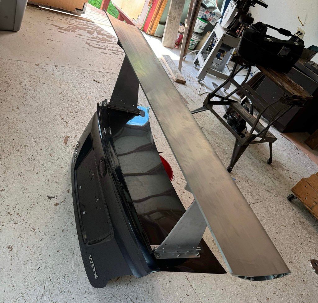
I wanted to see what would happen if I did that with endplates, but in reverse. So that’s what these first endplate tests are: start with a small rectangular endplate and get progressively larger. I don’t have the time (money) to dick around with 1″ increments like BBTI did, so I decided to make end plates at 3″ intervals: 6″, 9″, 12″, 15”, and 18”.
I didn’t start with a 3″ endplate, as that would have been only half an inch depth under the wing, and that seemed silly based on the size of the low-pressure region. And I didn’t go larger than 18″, for a couple reasons.
- I use recycled street signs, and anything over 18″ long means cutting into a 24″x24″ or larger sign, which is wasteful.
- I felt that if I extended the endplate over 18″, they might bend inward at the bottom. The aluminum signs I use are quite sturdy, but I’ve seen this bending on my buddy Bronson’s car, and it looks like anti-performance.
- Very large endplates are going to have considerably more side force. Meaning that they would move the center of pressure rearward, and that might have a greater effect on handling than whatever the endplate is doing to the wing’s performance. That’s a separate topic, and difficult to discuss without knowing the weight balance and silhouette of the car in question.
Simon McBeath published a similar test in Racecar Engineering, using CFD. He started with a small rectangular endplate and then increased the depth of the endplate by 50mm each time. He stumbled upon magical in-between size (125mm IIRC), which outperformed all the others. Keep this in mind, because it kinda happens later in the test, as well.
I won’t republish Simon’s results here, subscribe to Racecar Engineering and you can find that article in their archives. If you want to cross-list my data with Simon’s, note that Simon measured the depth below the wing, and I use the total endplate height. My endplate depth is about 2.5″ less than the total height, so a 6″ end plate has about 3.5″ of depth.
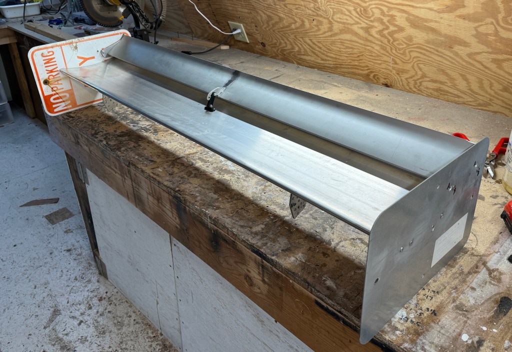
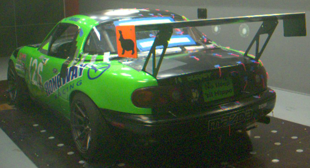
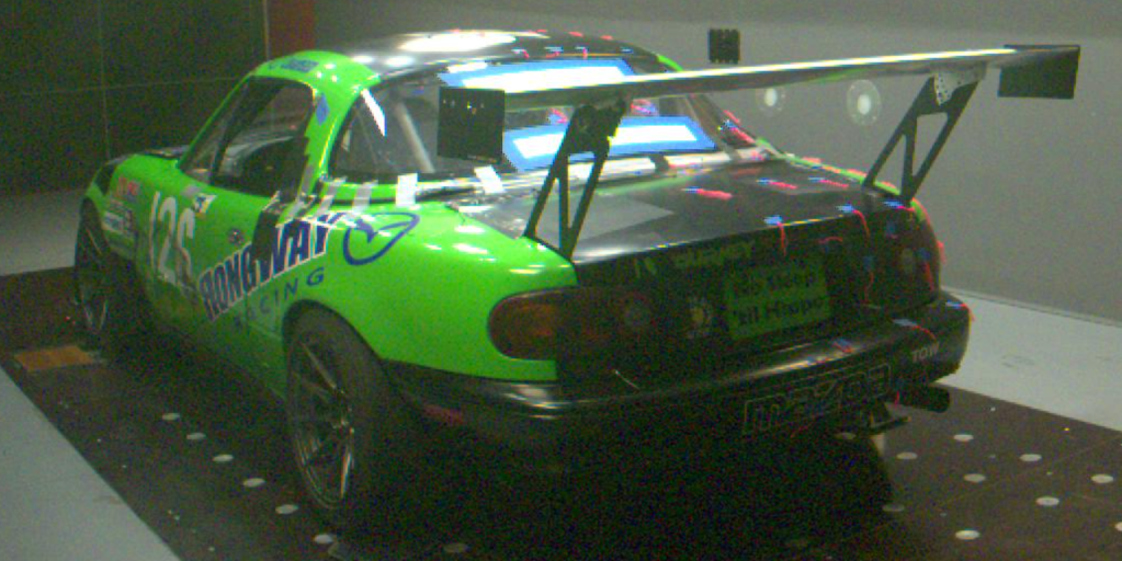
Note that I did the rectangular endplate test on my Veloster N with a 71″ Wing-Logic MSHD. I used reverse swan neck wing mounts mounted at roof height, with the usual quarter-chord overlap over the rear hatch. I feel the wing was high and wide enough that the body shape didn’t make much difference on the endplate performance, but it’s always worth noting that the car influences the wing and endplate.
The following table is listed in pounds (I’m embarrassed that I can’t think in metric; I’m too old to make the switch). Positive values are bad, negative values are good: less drag or less lift (= downforce). I list the total Lift, which is the lift at the front (Lift F) and rear (Lift R) added together. Rear downforce and drag can lift the front of the car, and it’s interesting to see that relationship here. I’ve also included a column for the L/D ratio the car, and how that changed with each endplate.
| Endplate | Drag | Lift | Lift F | Lift R | Car L/D |
| 12×6 | -0.5 | 1.5 | 0 | 1.5 | 0.88 |
| 12×9 | 0 | 0 | 0 | 0 | 0.88 |
| 12×10.5* | 1.1 | -0.8 | 0.35 | -1.15 | 0.88 |
| 12×12 | 2.2 | -1.6 | 0.7 | -2.3 | 0.88 |
| 12×15* | 4.7 | -2.55 | 1.15 | -3.7 | 0.88 |
| 12×18 | 7.2 | -3.5 | 1.6 | -5.1 | 0.87 |
Let’s take a look at that results in detail:
- 12×6 – The smallest rectangular endplate reduced drag by .5 lbs and lost 1.5 lbs of downforce. Not a great tradeoff, but also these are tiny numbers, and if you have 6″ endplates now, there’s no reason to “upgrade” them.
- 12×9 – This is a street sign cut in half, and is the endplate I put on every wing, to baseline the testing of other endplates. Its values are all zero, because everything else is being compared to this one.
- 12×10.5* – I didn’t test this size, the values in the table are an average between 9″ and 12″, which is a fair assumption given the data. I included this in-between size because it’s the same dimensions as the 9 Lives Racing Megga endplate, which, if we believe the advertisement, is supposed to increase downforce by 10%. I’ll be kind to 9 Lives Racing and compare the Megga-sized endplate to the 6″ rectangle, and you can see the larger endplate increased downforce by 2.3 lbs. Given that the wing is making about 260 lbs of downforce, this is less than 1% more downforce than a 6″ endplate. Claiming 10% more downforce is 1000% wrong.
- 12×12 -This is the maximum area allowed in NASA Super Touring, and I’ll go into more detail about that in the following section. It makes 1.6 lbs more downforce than the 9″, and trades that for 2.2 lbs more drag. These are nothing numbers, which is why the L/D ratio of the car didn’t change.
- 12×15* – I didn’t test this size for financial reasons, the values in the table are an average between 12″ and 18″. This seems a fair assumption based on how little things change, and there’s no reason to use this size IRL.
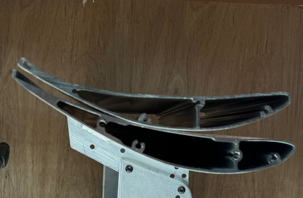
- 12×18″ – This is a full-length street sign, and made the most downforce, but also added 7.2 lbs of drag, which is equivalent to losing about 1 hp at 100 mph. The endplates bent inward from the suction below the wing, and this can’t be good, because this is the only endplate that changed the L/D ratio of the car, and it did so in the wrong direction. The A2 wind tunnel operates at 85 mph, and so at a higher speed, you’d see even more bending, and probably less efficiency.
After reviewing all of this information, it appears that every 3″ of depth adds about 1.5 lbs of downforce, but it also adds proportionately more drag. If we remove the 18″ endplate from the test, I can conclude that different sized rectangular endplates result in the same L/D of the vehicle.
In my testing, I found two exceptions to the above statement:
- We tested a 300×300 mm endplate (close enough to 12×12) endplate on Raul’s BRZ with a 68″ PCI wing, and the large endplate lost over 20 lbs downforce compared to a standard-sized flat rectangle. For whatever reason, on this wing, on this car, bigger was not better; it was quite a bit worse. I didn’t include this data in the preceding table, because I didn’t test my street sign endplate on his car, but something a little different in size. Anyway, avoid this size on a PCI wing.
- In this experiment, I didn’t find a rectangular endplate that was too small, but later in this article, the trapezoidal Wing-Logic endplate also underperformed compared to a 6″ rectangle.
Both of these were outside the Goldilocks zone of “not too big, not too small” and if I were to make a rule of thumb about rectangular endplates, I’d say make them about a chord in height. If you have a 9″ wing, then a 9″ tall endplate is about the right size. Unless you stumble upon some magical size, then going significantly over or under a chord’s height could be a lot worse.
144 sq-in shapes
NASA Super Touring rules specify a 144 square inch limit for endplates. Go over that size, and your car is illegal. The rule leads people to believe that bigger is better, but as we just saw on Raul’s PCI wing, bigger is sometimes a lot worse.
It begs the question, why did NASA create this rule? If you look at the rest of the rulebook and the aero values, it’s pretty obvious that guessing at aerodynamic performance, and not measuring it, is their modus operandi.
But let’s put that all aside for a moment and say that you want to maximize your endplate size for the NASA ST rules, the easiest way to do that is a square 12″ x 12″ endplate. But there are other size rectangles that result in the same 144 square inches. Indeed, there are other shapes that result in the same area, but that extend further below the wing. Theoretically, this should produce more downforce. Maybe we can get something for nothing?
I drew up a few endplate designs and sent them over to Tim Miller, and he suggested I try a delta shape with a long axis of 16″. This came out to 142 square inches, but close enough to 144.
Now you might be wondering which way the end plate faces? It’s a good question, and so I tested it both ways, delta forward (with the taper facing forward) and delta rear (with more surface area forward).
Note that the car, wing, and position of the wing are all the same as in the rectangular endplate tests. But this time I’m using the 12×12 as the basis, because it’s all about the max NASA size.
| Endplate | Drag | Lift | Lift F | Lift R | Car L/D |
| 12×12 | 0 | 0 | 0 | 0 | 0.88 |
| Delta forward | 2.1 | -1.6 | -0.2 | -1.4 | 0.88 |
| Delta rear | 1.9 | -2.5 | 0.4 | -2.9 | 0.88 |
- 12×12 – This is the basis for the comparison, and so all its values are zero.
- Delta forward – The endplate was placed such that the tapered edge faced forward, with more surface area to the rear. This made 1.6 lbs more downforce than the 12×12, but also more drag. End result, no discernable difference.
- Delta rearward – The same endplate flipped around so that it had more surface area forward, made more downforce. This makes sense, since much of the low-pressure region is ahead of and below the leading edge of the wing. What’s surprising is this direction also had less drag than the other way around. I’ve been saying this for years, that endplates should be designed with more surface area forward, and I feel vindicated with this evidence. But also, these are such small numbers that it didn’t change the L/D ratio of the car, and whatever point I was trying to prove is pointless.
At this juncture I can conclude that that any rectangular endplate from 6″ to 12″ tall, and probably any 2D shape, will result in the vehicle having the same aerodynamic efficiency. Unless you go too small or too large, or somehow luck into a size that has magical abilities, endplates of different sizes and shapes are just tiny tradeoffs between drag and downforce, and all of them amount to the same aerodynamic efficiency.
So if all 2D shapes and sizes are the same, what about 3D shapes?
Aviation-inspired experiments
I wanted to try a couple different endplate ideas based on things I’ve seen on aviation wings. These tests were on the Veloster with the 71″ MSHD, reverse swan necks, etc.
- Airfoil shape – The first experiment was to use an endplate that’s shaped like an airfoil, with a thick leading edge, tapering back to a sharp trailing edge. I made this out of foam and covered it with tape, and then stuck it to a 12×6 endplate. I eyeballed the shape, it was probably close to a Clark-Y. Theoretically, this should work better when the wing is in yaw (going around a corner), as the rounded leading edge should have better flow attachment, and the shape of the airfoil should kick air a little more sideways, making the wing seem like it has a higher aspect ratio.
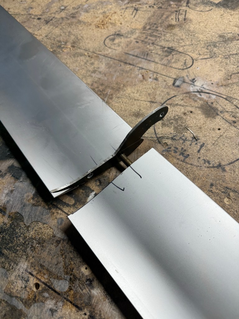
- Fillets – The other thing I wanted to try was to reduce the intersection drag between the endplate and the wing. You see this on airplane wings, at the wing root. That 90-degree corner where they meet is a place where flow separates, and radiusing that area should help flow attachment. I had my friend Alyssa 3D print me some plastic fillets with a radius.
While both of these ideas sounded great in theory, neither of them worked out.
| Endplate | Drag | Lift | Lift F | Lift R | Car L/D |
| 12×6 plain | 0 | 0 | 0 | 0 | 0.88 |
| 12×6 airfoil | -1.3 | 26.8 | 8.8 | 18 | 0.79 |
| 12×6 fillet | -4.8 | 24.7 | 9.7 | 15 | 0.81 |
- 12×6 – This is the plain rectangle I used in the endplates by the inch test. All of its values are zero, because the other endplates are based on this.
- Airfoil – Making the endplate thicker and shaped like an airfoil reduced drag, but it also lost 26.8 lbs of downforce compared to the unadorned street sign. The aerodynamic efficiency took a dive, down to .79. Ouch.
- Fillet – The fillet reduced drag even more, but downforce went down by almost 25 lbs. For a low-drag application like an airplane, where maybe lift is not the primary concern for long distances, perhaps this is a good idea. But for a car wing, not at all.
In retrospect, the airfoil shape was probably too thick, and reduced the effective length of the wing by 3″, which was the thickness of the airfoil, and about 4.5% of the span. Total downforce went down by 11.5%, which means there was still an unfavorable tradeoff between drag reduction and downforce. The airfoil shape would be most effective when placed in yaw, but I didn’t test that. There may be some benefit to thickening and rounding the leading edge, but not at the expense of reducing the area under the wing!
The fillet under the wing also shortened the effective wing length, and that’s probably why it lost downforce. It’s a similar problem to the airfoil shape. If I redesigned this, I’d radius only the trailing surfaces after the thickest part of the wing.
But neither one of these is a game changer, and in fact both were utter crap. The theme of “you get drag reduction or downforce, but not both” remains true.
CFD-designed end plates
My guesses at improving endplate design were interesting but not fruitful. Taking my ideas and shaping them into reality, and then testing them in a wind tunnel, is a slow and expensive process. People smarter than me do their development in CFD. This allows them to try many different iterations on the computer, and arrive at an acceptable tradeoff between drag and downforce.
But there are three common problems I see with the CFD approach.
- Testing – Nobody seems to test their CFD-designed endplates in a wind tunnel. They think (or rather, want you to believe) the CFD is valid, when in fact it’s never been calibrated by putting it into a feedback loop. “CFD-proof” isn’t proof; if you see those words you are being scammed.
- Free stream – Most of the CFD I’ve seen is done in free stream. The fact is, endplates should be designed not only for a particular wing, but for a specific car, with an exact wing size and wing location. If you test wings in free stream, meaning that the wing is suspended in air, but not attached to the car, you can absolutely design the most efficient endplate for any given wing. But when you put the wing on the car, the game changes entirely. Developing endplates (or any aero device) in free stream CFD and applying that to all cars is utter bullshit.
- Wing efficiency vs vehicle efficiency – Cars are large and draggy, and have shitty aerodynamics. In order to improve the L/D ratio, you need to make huge changes to downforce, not small changes to drag. Adding more wing angle makes the wing less efficient, but it makes the vehicle more efficient.
But if CFD isn’t real, the wind tunnel isn’t real either. In the real world we have winds from every direction, cars in front of us, and in the situations where when we want the most downforce, in a corner, the car is in yaw.
I didn’t test those things, and they are certainly important. So as much as I might malign CFD for giving us false hopes, I’m also acknowledging that wind tunnel testing isn’t 100% accurate, either. We are all doing the best we can, with the information we have available.
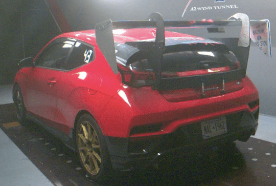
I tested CFD-designed end plates from Yeti Racecraft and 9 Lives Racing, which I cover below. At the wind tunnel we also tested some CFD-designed top secret endplates I can’t show any pictures of. The results were exactly in line with all of the other CFD-designed endplates, with their fancy vents, cuts, and shapes, and so I’ll wrap up that in the final conclusion.
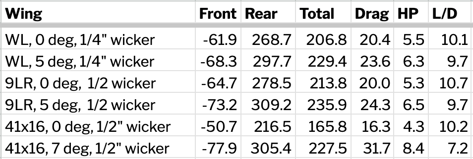
9 Lives Racing
9 Lives Racing sells four endplates, three rectangles of different sizes and a CFD-designed shape that has a couple cuts and a bend in it.
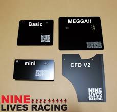
- The basic endplate measures 10” chord by 8” depth. The wing is positioned at the rear of the endplate, so that the trailing edge of the wing is at the rear edge of the endplate. This puts most of the endplate’s surface area in front of and below the wing, which is proper.
- The mini endplate looks to be the same as the basic, but with less depth. I didn’t test this one, but I’d guess it performs similarly to the 6” endplate I tested.
- The MEGGA!! endplate is larger than the basic in both directions, measuring 12” chord and 10.5” depth. I already covered this size in the Endplates by the Inch section.
- The CFD V2 measures 10.5″ chord by 12” depth with a semi-circular arc cut into the leading edge and a vent cut into the top side. It measures about 115 square-inches, well under the silly 144 square inch NASA Super Touring rule.
- Years ago there was a CFD V1 endplate, which had the same shape, but without the bend on the trailing edge. Based on the shape of the low pressure region below the wing, this semi-circular cut seems like it would reduce downforce, just the way that the Delta-shaped endplate I tested showed that more area forward was better than more area reaward. Anyway, I tested CFD V1 on a previous trip to the wind tunnel, and I ran it in both directions to test my hypothesis. I’ll include that data in the summary table.
Note that the these endplates were tested on two different cars, my Veloster N with a 55″ 9LR original (Express) wing, and Pete Mink’s Porshe 944 with a 68″ Evo wing. I didn’t include a vehicle L/D ratio column in the table, because I can’t relate it to both cars. In any case, you can probably guess that the vehicle L/D didn’t change much.
| Endplate | Drag | Lift | Lift F | Lift R |
| 12×9 rectangle | 0 | 0 | 0 | 0 |
| 9LR Basic | 0.8 | -7.2 | 1.2 | -8.3 |
| CFD V2 | 1.1 | -3.7 | -1 | -2.7 |
| CFD | 4.1 | -1.8 | -0.8 | -1 |
| CFD reversed | 3.5 | -1.5 | -0.4 | -1.1 |
- 12×9 – Street sign cut in half, everything here is compared to this.
- 9LR Basic – What’s super interesting about this endplate is how well it performed compared to the 12×9. It has 2″ less chord and 1″ less depth, and yet it made 7.2 lbs more downforce. Drag went up, which is what happens when you add downforce, but by less than 1 lb. Nevertheless, this is better performance, and if I had to guess, I think it has to do with a) stumbling upon a “magic” size, and b) positioning of the wing on the endplate. On the street sign endplates, I centered the wing fore and aft, but on this endplate, the wing is as far rearward as you can put it. This endplate shows that a proper rectangle is as good, or better, than most anything.
- CFD V2 – Compared to the Basic endplate, the CFD V2 makes less downforce and more drag. Which is odd, because their advertising claims the CFD V2 makes 10% more downforce and 7% less drag, and it’s actually worse in both directions. But maybe they were comparing that to no endplate at all? In any case, the Basic is better.
- CFD V1- I tested the first version of the CFD shape on my Veloster, and it made more downforce than the 12×9 street sign, but also more drag. When I reversed the endplate on the wing (the holes didn’t even match up, so the endplate was askew), the numbers were slightly different, but basically the same. This is no surprise, since we saw this already with the Delta-shaped endplates, putting them forward or backward didn’t move the needle. So it’s expected that the same result happened here.
Two things of interest came out of this test, one is that there is sometimes a sprinkle of magic in rectangular endplates, and one size may work slightly better than others. Simon found this in his CFD experiment, and I’ve found the same in this test, both in sizes that work better than they should, and sizes that are quite a bit worse. Now we are only talking about a difference of 7 lbs of downforce at 100 mph, and that wouldn’t change the performance of the car in a way that you’d notice. Still, it’s neat to see this.
The other interesting tidbit is the difference between the CFD original and CFD V2, with the rear bend on it. The rear bend added 2 lbs of downforce and reduced drag by about 3 lbs, and is an obvious improvement. While these are tiny numbers, they are at least going in the right direction. But the Basic rectangular endplate still outperformed both V1 and V2.
Yeti Racecraft
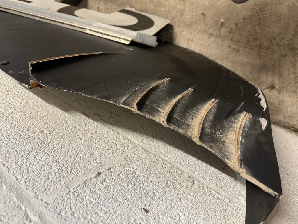
Yeti Racecraft is an aftermarket manufacturer making CFD-designed endplates and other aero parts. Yeti’s Brian Kemerley designs each one specific to an aftermarket wing. Meaning that Brian’s endplate for a PCI wing is a different size and shape as the one he makes for 9 Lives, which is different from the one he designs for Wing-Logic. This makes sense because the pressure distribution is going to be a different size and shape on different wings.
But the endplate shapes aren’t hugely different, they all have the same family resemblance, with more surface area forward than aft. A rectangular endplate forms a vortex on the corners, but Brian’s “swoosh” shape merges two vortices into one, which results in less drag. There are vents cut into the top, to bleed some high pressure air to the low pressure side, and a long tail with a notch in it, presumably to do the same.
Some of the Yeti endplates are flat, and some have a small Gurney flap on the trailing edge. Unlike the 9LR CFD V2 endplate, the Yeti bend is only on about half the trailing edge. In the data below you’ll see that this worked, although I wonder how it would have performed if the lower half had the flick on it, rather than the upper half.
These endplates were all tested on a Porsche 944 with a 68″ 9 Lives Racing Evo wing and their standard wing mounts. As a side note, I helped Pete install the wing mounts and I found them to be well designed and constructed.
| Endplate | Drag | Lift | Lift F | Lift R | Car L/D |
| 12×9 rectangle | 0 | 0 | 0 | 0 | 0.64 |
| Flat swoosh | -0.9 | -0.1 | -0.3 | 0.3 | 0.64 |
| Flick swoosh | 0.2 | -4 | 0.5 | -4.6 | 0.65 |
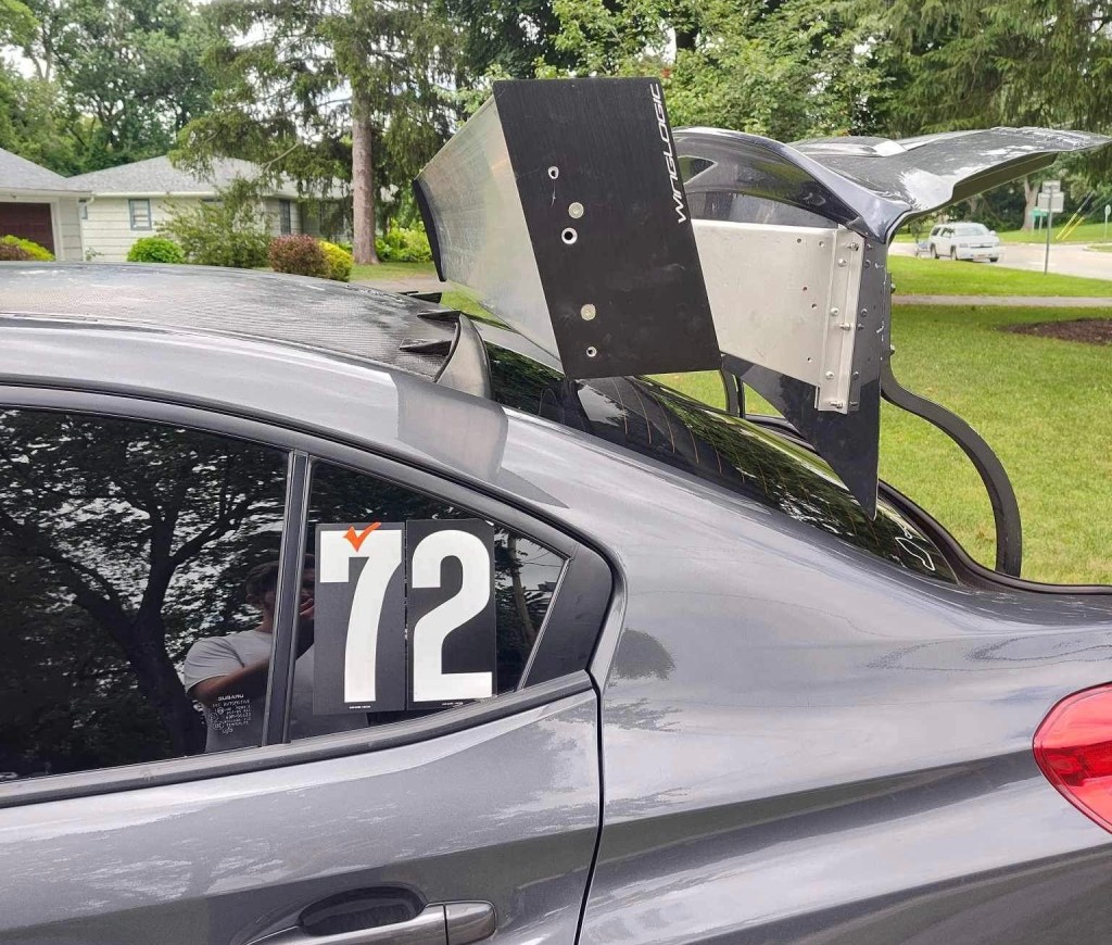
| Time Attack | 5.9 | -16.7 | 5.8 | -22.5 | 0.69 |
- 12×9 – Same rectangle, baseline for others.
- Flat – The swoosh shape, topside vents, and rear notch combined to do… not much. Compared to the basic 12×9 rectangle, the fancy shape had 1 lb less drag and .1 lbs less downforce. These are barely measurable figures, and no better than a generic rectangle, and worse than a 9LR basic.
- Flick – The same shape with a half-length Gurney flap gains 4 lbs of downforce and .2 lbs of drag. That’s so little drag that we can ignore it, and call it a 1.5% gain in downforce for free. Well, not exactly free since the endplates cost $175, but this is an actual performance gain, not fantasyland. But still the 9LR Basic was better.
- Time Attack – This endplate has a much larger top vent and a radical double bend at the bottom edge, which scoops air almost like an outboard wing. It made 16.7 lbs of downforce and added 5.9 lbs of drag. That’s a 2.8:1 L/D tradeoff, which is remarkably good. This is slightly better than the L/D you see when adding Gurney flap to a wing.
I have a knee-jerk reaction against CFD designed endplates, because most of what I’ve seen is an expensive product, supported by misleading claims, and a zero-sum result. But Yeti Racecraft has made at least one endplate that proves Brian can design a CFD endplate that outperforms everything else.
Given all the data on different shapes and vents so far, I’m not going out on a limb to say that the performance isn’t based on the shape of the endplate, but how the shape works in conjunction with specific bends Brian puts in the endplate. This isn’t magic or luck, but the kind of thing one arrives at by many hours of CFD work. You can’t copy this shape, send it to SCS, and get the same performance as the Yeti Racecraft endplate.
And shame on you for even thinking of that! Many hours of development time went into this endplate, and stealing someone else’s work makes you a thief. So if you want these endplates, buy them from Yeti and get the real deal. Don’t be an asshole and copy something that won’t perform as well, because you don’t know where to put the bends, how much to bend them, and how that changes for different airfoils.
OK, one nit: the description on the Yeti site says this endplate also reduces drag, and while that may be true in the CFD, it’s not true in the wind tunnel. No endplate adds downforce and reduces drag. But what is true is that this is an excellent endplate, that results in better vehicle efficiency than any other endplate I tested. Bravo.
Yeti also makes a hybrid shape that combines their basic swoosh shape with a less aggressive bottom bend than the Time Attack. I didn’t test this one, but it probably sits somewhere between their Time Attack and swoosh-flick.
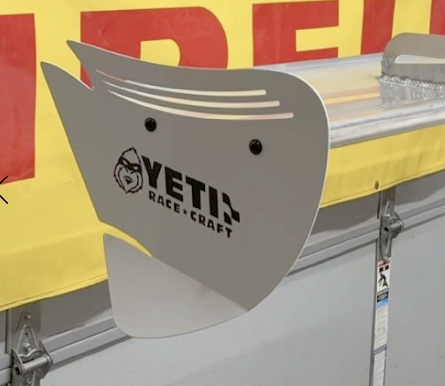
At the end of this article I give each endplate a grade, and the only thing keeping the Yeti Time Attack from getting an A+ is a couple adjustment holes. With an endplate like this, when you adjust the angle of attack on the wing, it also adjusts the angle of the “winglet” on the endplate. So I’d like to see adjustment holes here, so that the endplate can be pivoted a few degrees fore and aft.
Miscellaneous endplates
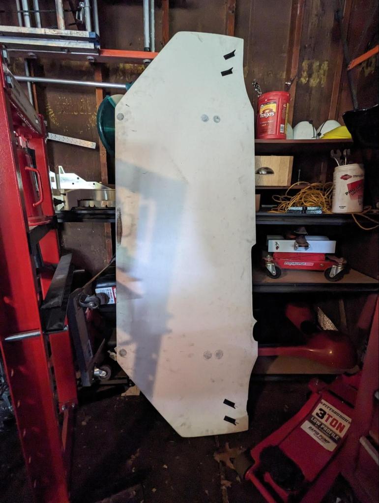
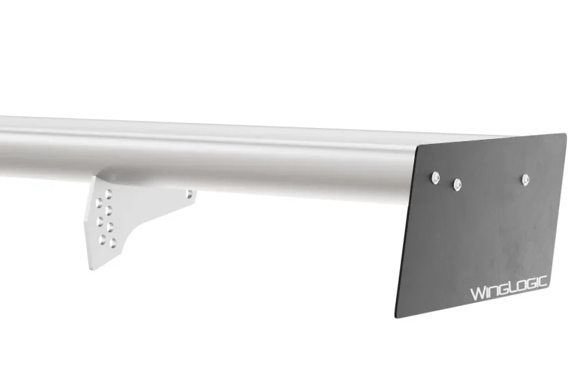
I’m going to add three more endplates to this discussion, the first is the endplates that come in the box when you buy a Wing-Logic MSHD, the next is the basic 12×9 street sign with a bottom vent, the last is an endplate I made back in 2019.
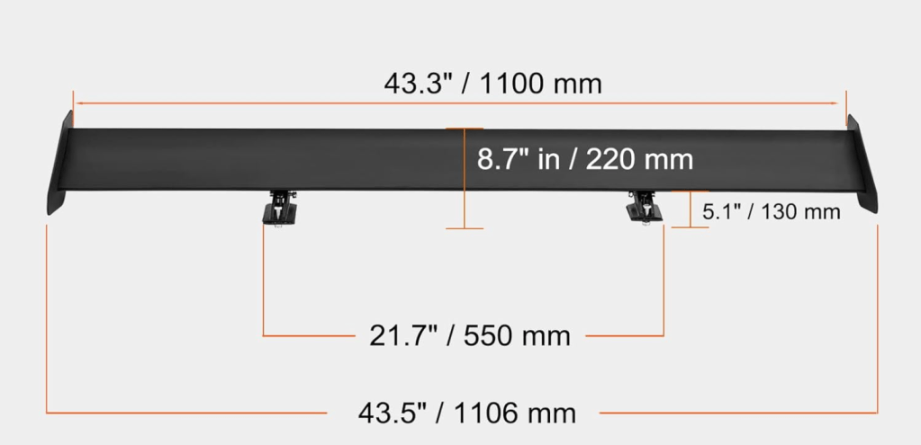
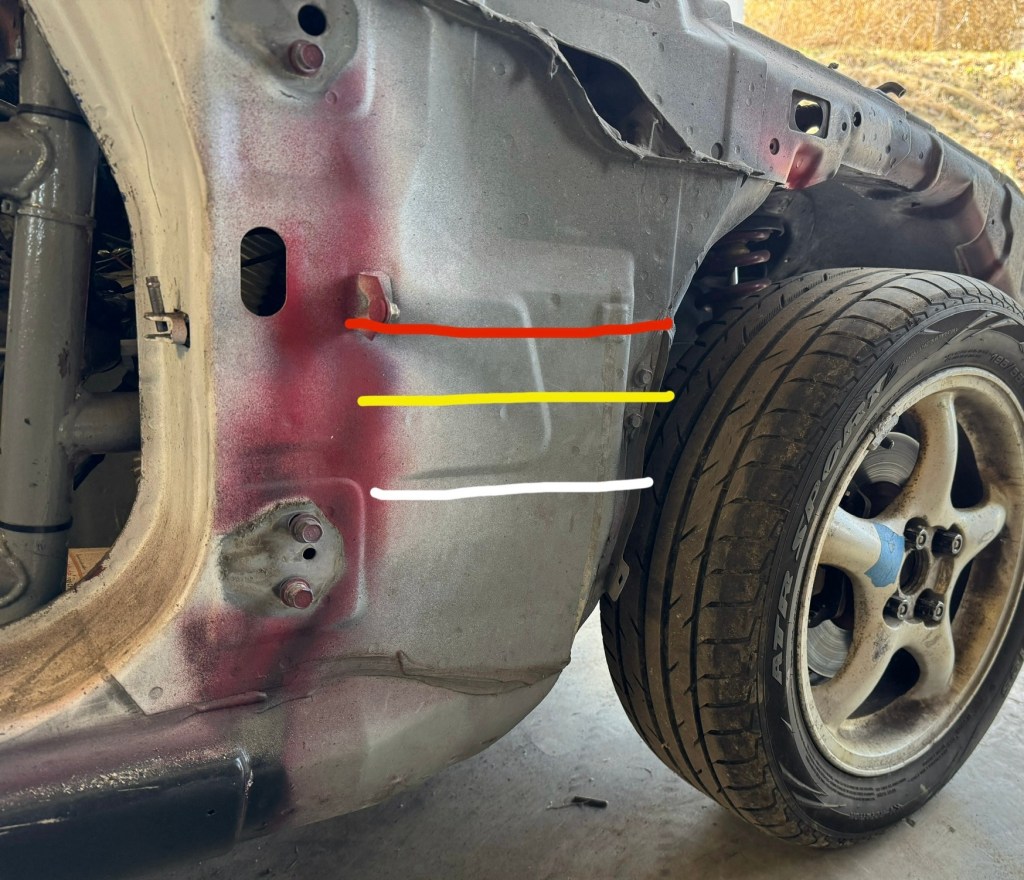
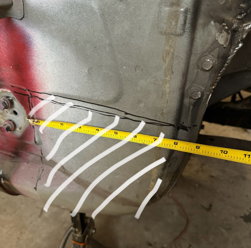
The Wing-Logic endplate is a 10×5.5 parallelogram. This is the smallest endplate in the test. It doesn’t come pre-drilled, and so I placed the endplate about where I placed the rectangular endplates, with most of the area below the wing.
The next one is the standard 12×9 street sign, with a single slash cut into the bottom of the endplate, and then bent such that it directs air from the outside of the endplate into the wake behind the car. The purpose of this is to (theoretically) reduce the trailing vortex and reduce drag. There’s no picture of this one, not because it’s a secret, but because you don’t want to do it.
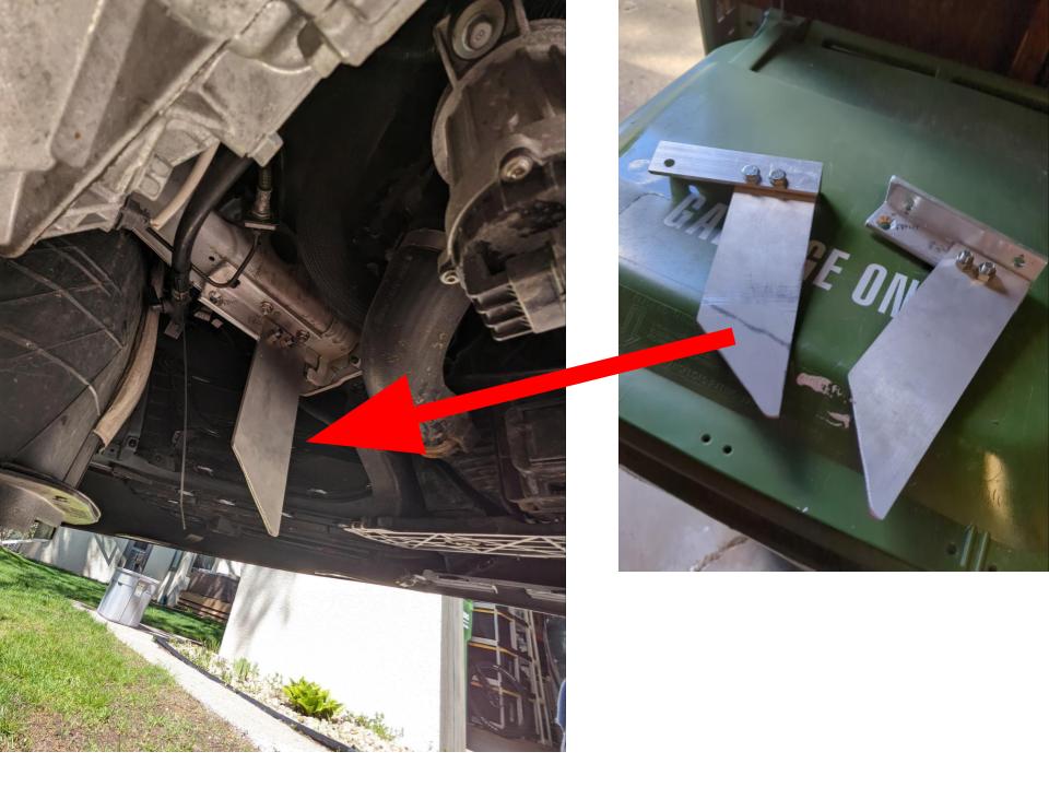
Finally my Occam’s Racer endplate was one I made back in 2019. I shaped it so that there’s more area forward and less at the trailing edge. I put a notch in the top side trailing edge, because I’ve seen that on other endplates, and I bent a small 90-degree Gurney flap into the trailing edge.

The endplates were tested on different cars and with different wings, but I did baseline the 12×9 endplate on every comparative test, and so we can have a valid discussion about the results.
| Endplate | Drag | Lift | Lift F | Lift R |
| 12×9 rectangle | 0 | 0 | 0 | 0 |
| 12×9 vented | 2.8 | -2.4 | .8 | -3.2 |
| Wing-Logic | 4.2 | 11.3 | 7 | 4.3 |
| Occam’s Racer | 6.9 | -8.9 | 0.8 | -9.6 |
- 12×9 rectangle – Baseline for all runs.
- 12×9 bottom vent – I thought the bottom vent would reduce the wingtip vortex, thereby reducing drag, but it actually did the opposite. By adding outside air into the wake downstream, it energized the flow and downforce went up by 2.4 lbs, which surprised me. However, drag went up by 2.8 which is the usual tradeoff, and not a very good one, at that.
- Wing-Logic – This is a really weird and useful result. The total area is 55 square inches, which is not that much smaller than a a 12×6 rectangle at 72 inches, which you may recall performed about the same as a 12×9. However, the Wing-Logic endplate lost 11.3 lbs of downforce and gained 4.2 lbs drag. Ergo, this endplate is undersized, and doesn’t block enough of the high- and low-pressure regions, resulting in losses both ways.
- Occam’s Racer – We’ve already seen that shapes are basically meaningless, and I doubt that top notch does anything, so the 9 lbs of downforce is probably down to the Gurney flap alone. This comes with a drag penalty, and the resulting 1.29 L/D ratio would only be beneficial on a car with lousy aerodynamics or at low speed.
The key takeaways from these tests are that there is an endplate size that is too small, and we found it. We also found out that bottom vents are a zero sum modification, just like most everything else. While the Gurney flap worked to increase downforce, I think it was too aggressive and too vertical. Angling the flick upwards, like Yeti does, makes more sense.
Conclusions
An endplate can be designed to reduce the strength of the wingtip vortex, and thus reduce wing drag. This can be accomplished by cutting vents in the top of the endplate, or using a 3D airfoil shape, or radiusing the intersection between wing and endplate, or shaping the endplate to combine smaller vortices into one. From my testing, I can say that anything that reduces drag also reduces downforce.
Conversely, an endplate can be designed to increase downforce. This can be simply a larger endplate, or sending more air sideways using a Gurney flap on the trailing edge, or mixing outside air into the wake, or by deflecting air upwards. From my testing, I can say that anything that increases downforce, also increases drag.
Combining the drag reduction tricks with the downforce producing tricks is a zero sum game. Of the endplates I’ve tested, there is no endplate that both reduces drag and also increases downforce. None. Most modifications to the size, shape, vents, etc., all result in a vehicle with the same L/D ratio.
However, that doesn’t mean the performance would be exactly the same. You might want to choose the endplate that has the least drag for a high-speed track, and the most downforce for a low-speed track. It’s a very minor consideration, but it’s worth noting that overall vehicle efficiency doesn’t mean it’s the same performance. Although what you’re really after is better vehicle efficiency.
Because cars are large complex objects with terrible aerodynamics, endplates that increase downforce usually results in the vehicle having a better L/D ratio, even though the downforce-producing endplate adds drag. For example, if your car has a L/D of 1:1, then any aero modification that is better than a 1:1 L/D ratio is going to improve the aerodynamic performance of your car.
Of the endplates I tested, only the Yeti Racecraft Time Attack endplates improved downforce and vehicle efficiency by a meaningful amount. As such, the Yeti Time Attack endplate is the clear winner of this test. Everything else is meh, or worse.
And here’s where a real opportunity lies. If you replace the Wing-Logic endplates with the Yeti Time Attack, you’d get something like 28 pounds more downforce for not even 2 lbs of drag. This combination should be offered out the door, because that’s about 10% more downforce for almost no penalty to drag. Wow. Loot. Wing-Logic and Yeti Racecraft need to get together and offer this peanut butter and jelly sandwich.
Other than combining this worst-of case with a best-of case, there isn’t a lot to recommend one way or the other. These are tiny numbers, people. For most of us, a plain rectangle one chord in height is going to perform as well as anything else. Any amount of time and money spent developing something better than a medium-sized rectangular end plate is better spent doing anything else, anywhere else on the car. Spend this time, money, and energy on your spouse.
At the highest level of motorsports, I’m sure it’s possible to design an endplate that works with a with a particular wing, on a specific car, at an exact angle, height, and setback distance. With those variables locked down, maybe there’s a minuscule gain in performance? But on all the cars, wings, and endplate combinations I’ve tested (and some data I can’t share), the different shapes, sizes, cuts, vents, etc., do nothing for the performance of my car.
There are a few things I didn’t test, or rather would re-test, given unlimited funds. As it is, I don’t plan to test endplates ever again (NEVER AGAIN – I’m shouting). But if I did…
- Position – Placing the wing further rearward on the endplate, such that the trailing edge of the wing and trailing edge of the endplate aligned, seemed to be better. Whether this was because there’s more surface area in front of the wing, or whether it’s because there’s less surface area after the wing, I don’t know. Flying in the face of that generalization are the Yeti endplates, which all extend rearward a good amount, and they were all pretty decent. I should have cut one of the Yeti endplates right at the trailing edge to see what happens. But if there are gains to be had, they are likely to be pretty small.
- Yaw – Race cars go around corners, and in doing so, typically have around 5 degrees of yaw. As a result, thin and flat endplates will experience some degree of flow separation at the leading edge. 3D endplates, with thick radiused leading edges would seem to be better in this regard. I tested thicker endplates, which were not good, but perhaps in yaw, they would have been? Maybe with a different airfoil profile? That mystery remains.
In the end, endplate performance doesn’t matter much. So perhaps the least important performance aspect is the most important purchasing decision: how the owner feels about it. If you like the look of a certain endplate, buy that endplate. If you’re a fanboi of a particular company, buy their endplates. And if junkyard-chic appeals to you, go to a scrapyard with $2 and cut a street sign in half.
Side force and center of pressure
Before I wrap up this article I want to discuss one more datapoint that I included in the final table of results: side force. This value ranged from -1.7 lbs to +5.7 lbs, with larger endplates having a greater side force, as you might expect.
I can’t tell you how much side force is going to affect the handing of the car; all cars are different, and I haven’t experimented with it myself. But any surface area at the rear of the car moves moves the center of pressure rearward. Station wagons and hatchbacks, with their large cargo areas, and LeMans prototypes, with their shark-fin bodywork, all move the center of pressure rearward.
Moving the center of pressure rearward changes how the car handles. The distance between the center of gravity and the center of pressure is called the static margin. From a driver’s perspective, a low static margin means the car gets looser at high speed. Conversely, a higher static margin means more high speed stability, and fewer corrections when the car goes over the limit. But the tradeoff is a car that is harder to steer, or may in fact understeer at high speed. Since wings are at the very rear of the car, the size of the endplates can have a significant effect on the static margin.
On a mid- or rear-engine car, the center of gravity is rear biased, and the static margin is low. Using larger endplates is a way to increase the static margin, and gain some high speed stability. If I had a 911, I’d use big-ass endplates.
Conversely, on a FWD hatchback, there’s a lot of weight up front, and a lot of surface area on the rear of the car, which results in a very large (too much) static margin. In this case, I’d use smaller endplates, because I don’t want to make a bad situation worse.
So when you look at the summary table, you might use the side force value and the weight balance of your car as another variable that factors into your choice of endplates. We already know that most endplates aren’t doing much to affect the car’s performance, and so side force might prove to be more important than a couple pounds of drag or downforce, this way or that way.
I’ll leave you with this summary table and a subjective performance grade. The price of the endplates isn’t factored into the grade, or you’d see a bunch of street sign trash at the top of the list.
| Endplate | Grade | Drag | Lift | Side | Cost |
| Yeti Time Attack | A | 5.9 | -16.7 | -0.6 | $200 |
| 9LR basic | B+ | 0.8 | -7.2 | -0.5 | $72 |
| Yeti flick | B | 0.2 | -4 | -0.7 | $175 |
| Yeti swoosh | B- | -0.9 | -0.1 | 0.3 | $150 |
| Occam’s Racer | B- | 6.9 | -8.9 | 0.2 | $10 |
| 9LR CFD v2 | B- | 1.1 | -3.7 | 0.9 | $240 |
| 12×6 | C | -0.5 | 1.5 | -0.7 | $2 |
| 12×9 basic | C | 0 | 0 | 0 | $2 |
| 12×9 bottom vent | C | 2.8 | -2.4 | 1.7 | $2 |
| 12×16 Delta R | C | 4.1 | -4.1 | 2.3 | $4 |
| 12×16 Delta F | C | 4.3 | -3.2 | 3.5 | $4 |
| Megga (12×10.5*) | C | 1.1 | -0.8 | 1.35 | $198 |
| 12×12 | C | 2.2 | -1.6 | 2.7 | $4 |
| 12×15* | C | 4.7 | -2.55 | 4.2 | $4 |
| 12×18 | C- | 7.2 | -3.5 | 5.7 | $4 |
| 9LR CFD v1 | C- | 4.1 | -1.8 | 2.2 | n/a |
| 9LR CFD v1 rev | C- | 3.5 | -1.5 | 1.2 | n/a |
| 12×9 fillet | D | 0.3 | 4 | 1.8 | $10 |
| Wing-Logic | D | 4.2 | 11.3 | -0.1 | $0 |
| 12×6, airfoil | F | -1.3 | 26.8 | -1.7 | $2 |
| 12×6 fillet | F | -4.8 | 24.7 | 0.6 | $10 |
| If you found this information useful, please Buy Me a Coffee. I’ve spent over $2000 testing endplates in a wind tunnel. The time to build, organize, and write that all up is not included. You may have noticed there are no ads or popups or other annoying shite on my website, because you probably hate that as much as I do. Please support science, open data, and further testing by buying me a cuppa. Thanks! |