As air moves over the top of a car, it follows the contour of the roof, changing in shape and direction. Most car wings are a 2D design, meaning they have the same shape across the entire wing, and thus aren’t optimized for a curving roofline. Ergo, at various points along the wing, the effective angle of the wing changes.
The easiest solution is to get the wing as high as you can, into the cleanest air. Many racing series limit wings to roof height, and even if you’re allowed to get it higher than that, there are practical limits to how high you can brace that much weight, and the ill handling that results from it.
Ideally, a wing should follow the shape of air as it goes over the car’s roof, and so 3D wings make a lot of sense. However, 3D wings have a complex shape, and thus aren’t easy to build. And they’d have a different ideal shape for every car, and maybe even on the same car at different heights.
Finally, for any wing, you need to know where to set it for the best lift/drag ratio, or the most downforce, and for sure you want to avoid too much angle, which will make the wing stall. Many wing manufacturers publish CFD data, but how does that relate to what’s happening on your car? I wanted to find out.
Airflow visualizer
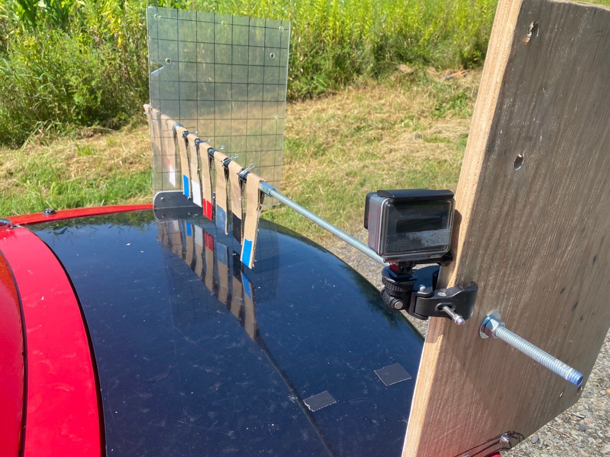
To investigate the shape of air as it comes over the roof, I’ve created what I call an airflow visualizer. It’s basically a metal rod suspended where a wing would be, with small pivoting airfoils that move into the position of least drag. With this visualizer I can measure the angle of air as it across the back of the car. This allows me to discover the ideal wing shape at any position behind any roof.
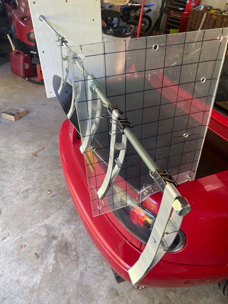
To build the airfoil visualizer I used all-thread so that I could attach it to wing stands of any width, and placed 9 Lives Racing “mini wangs” at intervals using binder clips so I could slide them around anywhere. I placed the last airfoil at body width, which would be a 64″ wing on this car. Given that car roofs are symmetrical, I only put airfoils on half the wing, and mounted a camera on the other side to capture what happens at speed.
My airflow visualizer has two end plates, one is wood, the other a clear acrylic. The all-thread rod goes through the end plates and I can mount the visualizer anywhere I want by drilling a couple more 1/2″ holes. On the clear side I put 2″ grid lines for measurement, and so that I could see the angle of apparent wind. The grid lines are at a 7 degree downward angle, which was a mistake, but turned out to be a happy accident.
Now I thought this was a great idea at the time, but because of the mass of the mini wings, I had to go very fast before they would pivot, and their inertia meant they also swung when I hit bumps in the road. In the end, this brilliant idea didn’t give me a clear picture of the airflow.
I then switched to using yarn in place of the wings, but that didn’t work great either, too much amplitude. I needed to dampen the signal as it were, so I taped 2″ wide strips of cardboard around the all-thread, which was a lot better. This was such a cheap and easy solution that I’m regretting cutting up all those mini wings now.
In the next section, I’ll explain what I’m seeing in the video. (If you see something different, drop me a note in the comments.)
Roof-height
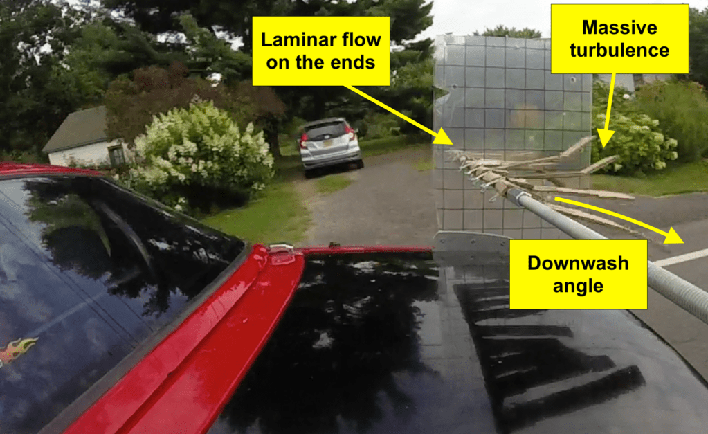
In the following video still, I’m doing about 20 mph and all the cardboard telltales are going straight back without any up or down movement. The telltales at the end of the wing are level with the road, and the ones in the middle of the wing are level with the black lines on the acrylic plate. So this means there’s about a 7 degree downwash angle on the sides of the roof, and what looks like 5 degrees in the center.
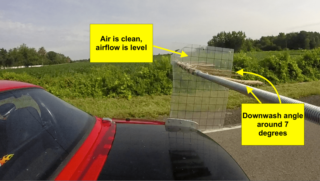
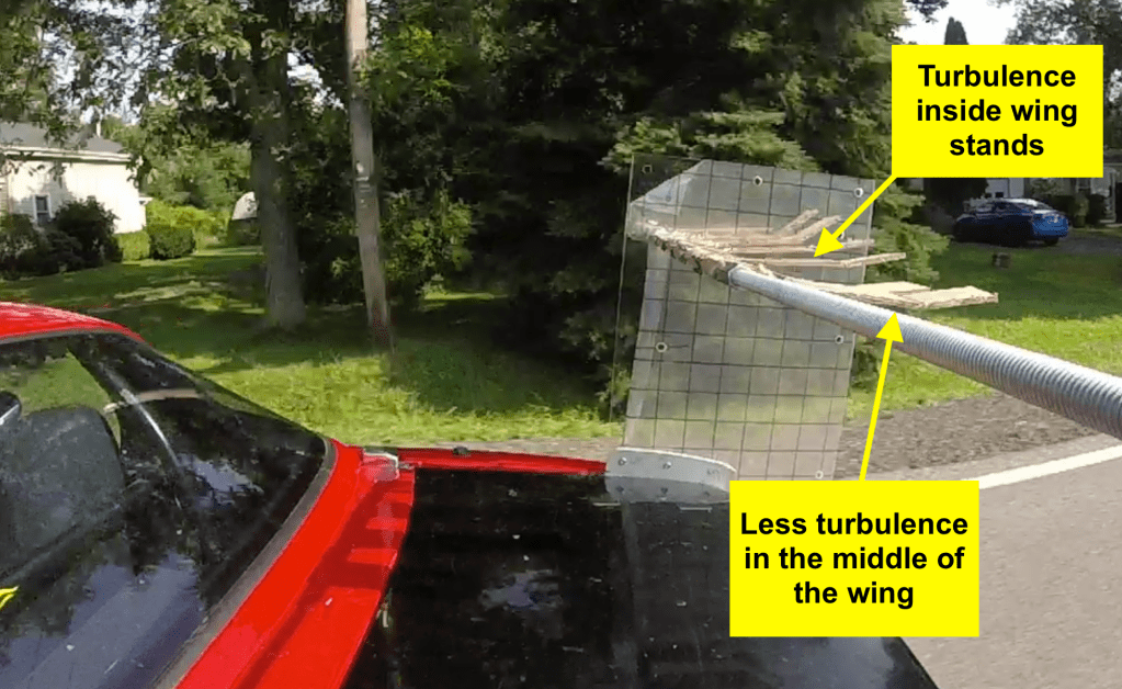
As I picked up speed, the telltales stayed at the same angle, so it doesn’t look like downwash angle changes much with speed. However, the telltales that are next to the acrylic plate started oscillating up and down like crazy, the result of turbulence. The middle of the “wing” shows some increased turbulence at speed, but nothing so extreme.
I’m guilty of confirmation bias; I like predicting results and then finding out they are true. I predicted nothing like this, and I liked that even better! Well, let’s see what happens when I lower the wing to half the height.
Lower height
The lower mounting location replicates a wing at 8″ high. The telltales at the end are just higher than the grid lines on the clear end plate, so it looks like a few degrees negative. I expected to see them at zero degrees, but perhaps there’s some interaction with the sides of the car or the road at this height? Whatever the case, something is creating a slight downwash angle.
In the middle of the car, the downwash angle is greater, maybe 15 degrees, and as speed increases, so does the angle. If you watch the video, it looks like that the air near the trunk is pulling the center foil downward at speed. As you move from the center to the sides, the angle changes a bit. And again there’s a shocking amount of turbulence on the three telltales near the wing stand. You can see this in the video: at about 20 mph, all of the cardboard goes straight back, but by 40 mph, the telltales near the mounts are flapping up and down like crazy.
Re-tests
The cardboard strips have a bend in them at the end, and I wondered what would happen if I cut this flexible section off. I did that and re-tested both heights and much of the turbulence went away. That dampened the signal too much! It occurs to me that if I started that way, I never would have discovered the turbulence.
I then moved the airflow visualizer 4″ higher and 12″ further back. Theoretically the air should be a little cleaner here, with less change in angle across the wing.
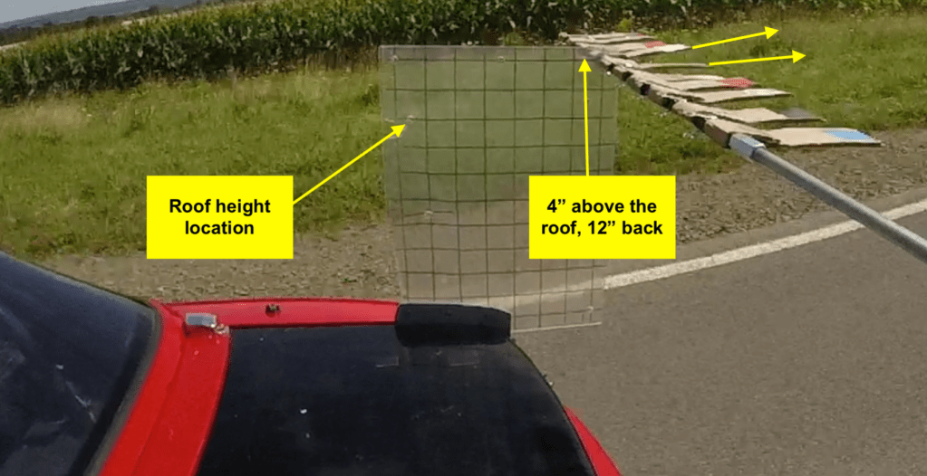
The downwash angle flattened out a little bit. Look at the two telltales on either side of the acrylic plate, that’s where the angle is the greatest. In the middle of the wing, the downwash angle is little bit less.
I then kept the hight the same and moved the visualizer 6″ forward. So this splits the difference between the first run and the last. It was pretty similar, and so I’m not sure moving the wing rearward further than this has much benefit. In fact you lose downforce and create front end lift by moving a wing too far rearward.

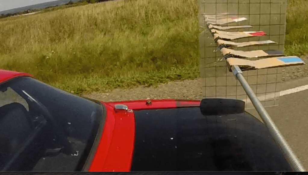
I then retested at roof height and forward, and here you can see the 7 degree downwash angle on the telltale that’s inside the wing stand (level with grid lines), and the one on the outside is level with the ground. The telltale that’s in the exact middle of the roof appears to have slightly less angle.
Early conclusions
My testing is far from over, but I can draw some early conclusions.
For a 2D wing, get the wing as high as your rules allow, but within reason. At some point the extra weight and moment of inertia will be detrimental to fast changes of direction; a tall, wide, heavy wing at the polar end of the car is the antithesis of mass centralization. In addition, a higher wing causes front end lift because it has more leverage to rotate the entire car around the rear axle. All of this is to say that from from the wing’s perspective, it wants to be as high as possible, but from a handling perspective, lower is better. Somewhere around roof height is a good rule of thumb. This is not groundbreaking knowledge, I think most people do this already.
If you mount your wing at roof height, do you need a 3D wing? No. I’ve done the calculations for a 5-degrees offset, and there are very minor gains: 5% max downforce and 10% average gain in efficiency (entirely drag related), which is completely irrelevant at practical racing speeds. At 7 degrees, it wouldn’t be that much different.
It’s worth noting that with the wing 4″ higher than the roof, the downwash angle flattened out slightly. I would imagine there’s less turbulence at that height as well, but I couldn’t tell because I’d cut the telltales shorter before I tested that. In any case, if your rules allow you to place a wing above roof height, there’s some small benefit.
If you are limited in height to say 6″ below the roofline (SCCA Super Touring), then a 3D wing might be a better option. On a Miata, at this height, the change in angle between the ends of the wing and the middle is 10-15 degrees and this would likely cause a 2D wing to stall somewhere along the length. This of course depends on the roofline shape, and a car with less curvature in the canopy (E30, etc.) would be fine with a 2D wing.
The wing stands are 41″ apart, and so if I was designing a 3D wing for a Miata I would make the center section about 41″ wide, and put the outsides at a steeper angle. My guess is that the wing stands themselves are affecting this, by guiding the air along them, and that the center section that has more downwash angle is in reality a bit narrower than 41″.
If you have a 3D wing, I wouldn’t mount it at roof height unless the offset between the ends and middle is 7 degrees or less. All of the 3D wings I’ve seen have 10-15 degrees offset, and it’s likely that part of the wing will stall if mounted at roof height. You can find out the ideal placement of a 3D wing by making your own airflow visualizer, but lacking that, I would find pictures of wind tunnel streamlines for your car and measure them.
In fact I could have gotten pretty close using the following image from a wind tunnel test. However, it wouldn’t have told me the width of the center section that’s at a steeper angle, nor the massive turbulence hitting the inside third of the wing.

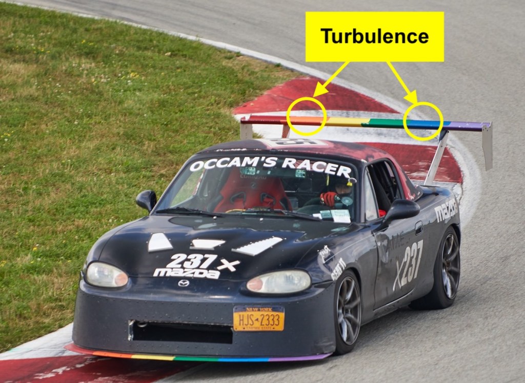
The cause? My guess is that air is wrapping around the sides of canopy, add it must detach in this region. This makes a lot of sense, because air doesn’t like to change direction at more than 12 degree or so, and needs help in the form of strakes, vanes, and other tricks to do so. This is true whether we’re talking about air going over a roof, under a diffuser, or around the sides of the canopy. The Miata’s hardtop wraps around too abruptly on the sides, and air can’t stay attached. The result is downstream turbulence hitting the wing.
And that’s probably the biggest discovery in all of this, which is that there could be enormous gains in feeding the wing cleaner air. The OEM Miata hardtop looks cute, and it functionally covers the hole where the soft top used to be, but probably 25% of the wing area experiences turbulence that decreases downforce and increases drag.
Changes to roofline shape, adding guide vanes, a spoiler, and perhaps even vortex generators on the sides of the canopy could be tricks that decrease flow separation in this area, and make a wing perform better. A 3D wing is not the answer to this problem, it would experience the same turbulence in this location, or perhaps more, being mounted lower.
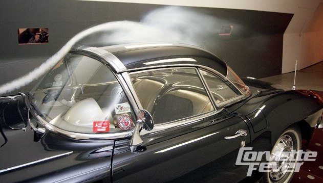
The following photo is from a wind tunnel test of six generations of Corvettes, this one an early hardtop version that’s similar to a Miata hardtop in shape. You can see the turbulence and separation along the side of the canopy. If you watch the video, you can see the flow stays attached down the middle of the car; it’s the air trying to wrap around the sides of the canopy that’s the problem.
Future tests
Now that I’ve built the tool, there are a number of tests I still want to do.
- New telltales – The sensitivity of the winglets plays a big part in visualizing what’s happening, and I have some ideas that are better than strips of cardboard. Ideally I’d measure the angle, amplitude and frequency using a potentiometer.
- Spoiler – You don’t see many people using a spoiler and a wing, because racing rules seldom allow that, but a spoiler might be useful to change the shape of air before it hits the turbulent portion of the wing. Yes the spoiler is behind the canopy, but it could build up a local high pressure region in front that might help in some mysterious way. Anyway, probably can’t make it worse.
- Custom top – I have three custom tops I’ve built (fastback, shooting brake, coupe), and I’ll update this post when I test them. But knowing what I know now, I have an idea for a new roof that has the specific task of feeding the wing clean and level air.
- Different cars – I can clamp the airfoil visualizer to any set of wing stands and change the width using the all-thread rod. With that I can measure the airflow on any car, at any height. Maybe I’ll create a database of “wind shapes” for different vehicles?
- Wing stands – My airflow visualizer is basically two enormous wing stands, and perhaps this is affecting the telltales that are immediately next to them. I’ll mount the airflow visualizer to standard wing mounts and see if there’s any change.
- Open top – In my aero tests at Watkins Glen, an open top reduced the wing’s downforce by 2.5x. At the time I didn’t know if this was turbulence or a change in wing angle, but at this point I’m leaning towards turbulence. On second thought, I probably won’t bother testing the airflow visualizer with an open top, because anyone using a wing and open top needs more help than I can give them.


I have NC with hardtop. I can source GTC-300 3d wing. What height do you suggest to use optimal? Outside US there is not much choice for aero for miata.
LikeLike
For most wings, roof height is optimal. For 3D wings, you can mount lower. I’m not sure what the angle offset is between the center and outsides of the GTC300, so it’s hard to say where you should put it. Maybe contact APR.
LikeLike
Nice work. I’ve done lots of similar testing using fishing line to locate wool tufts in strategic areas like between the wing and rear window. Wool tufts also used on rear window and sides of canopy. My testing has been with an S2000 with hardtop. One interesting and likely relevant finding is the massive turbulence at the sides of the canopy due to open windows. Closing the windows makes a huge difference – attached flow on canopy and rear window. I’ve tried various deflectors with minimal improvement. Might be an interaction with the wing mirrors as well.
LikeLiked by 1 person
Great info, thanks for sharing. I tried following your blog, but WP would allow me to. I’d like to know more about your experiments. Some thoughts to add to the turbulence conversation. Since HPDE and racing are done with open windows, maybe we can smooth the transition in this area either at the A-pillar (quarter window deflector), B-pillar (NASCAR-style smoother), and C-pillar (guide vane). Mirrors could be up on front on the fenders old school style. And there could be a forward bulge on the fender like a Porsche 914’s turn signals. If you read my post on that, the yarn tests show air being pulled down the side of the car and away from the windows.
LikeLike
Really nice work here! Im a sucker for legit backyard eyeball engineering!
LikeLike