Earlier this year I installed ARK lowering springs, which lower the car 1.25” front and 1.15” rear. I chose ARK springs because they are only slightly stiffer than OE springs (134% stiffer front and 125% rear), and that should allow me preserve the Veloster’s decent road manners. Most lowering springs have a higher spring rate than ARK’s 263 F and 336 R, and would beat the shit out of me on potholed New York roads.
I chose lowering springs over coilovers mostly for the price ($250 on FB marketplace), but also because I like messing around with the OE shock settings. I set my N Custom mode for medium stiff suspension when on track, but can quickly soften the suspension on the touch screen, for rain or street.
Lowering springs alone can reduce roll stiffness and increase bump steer, so they aren’t always a performance benefit. So I also installed the Whiteline front roll center bump steer correction kit. As near as I can tell, the combination of lowering springs and Whiteline kit have improved the handling, and I don’t feel a hint of bump steer or any negative handling traits.
I tested the lowering springs in the A2 wind tunnel, and it resulted in less drag and less downforce than when the car was on OE springs. If you’ve read my wind tunnel report, you’d know the Veloster makes a little bit of downforce, straight from the factory. With the lowering springs, this turned into a small amount of lift, mostly on the rear. That was surprising, as I expected that lowering the car would increase front downforce, but the front also lifted a little.
Lowering the car also reduced drag, which was probably a result of less frontal area and less air going under the car. It’s not a huge change (.014), but the result of both drag and lift shows a very, very slight aero advantage over the base car.
One caveat is that I didn’t use the same wheels and tires on my second trip to the wind tunnel. I made a mistake and had my track wheels and tires (18×8.5 +43 with 235/40R18 tires) rather than the OE wheels I used on my previous trip to the wind tunnel (19×8 +55 with 235/35R19 wheels). This put the tires 18mm (3/4”) wider on each side, and could account for some of the difference in lift, but not drag reduction.
New splitter mounts
I also improved the splitter mounts both in front and in the rear. I placed the support rods further apart on the bumper, which reduces the angle of the rods. The rods are turnbuckles from the Lowe’s racing department, allow easy height adjustment, and with 3/8” bolts, are plenty strong.
I also made a new aluminum rear undertray and added a full width piano hinge to it. Thus, the entire splitter can be adjusted via the splitter rods, which changes the height and angle of attack on the splitter.
Splitter has wider support rods and a hinged undertray.
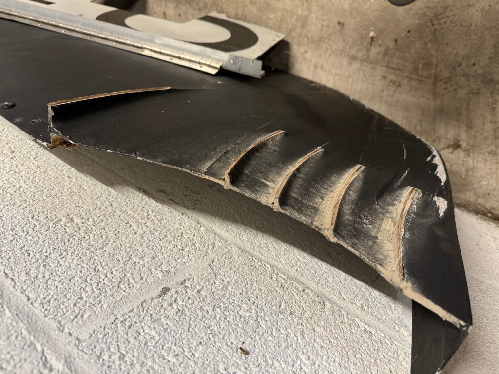
But the lowering springs are too soft or too low, because the splitter touches down on bumps and compression turns. In fact the vortex strakes I put so much work into have now been ground down to insignificance.
Vortex strakes clearanced out on the asphalt grinder.
I figured I have three choices going forward:
Revert to OE springs – The lowering springs aren’t much of a performance benefit, and if I had to do it all over again, I wouldn’t.
Coilovers – Digressive coilovers with heavier springs would swallow hard bumps on the street and curbs on track, while allowing stiffer springs. I’d also be able to corner balance the car, and change ride height. And I could still change suspension compliance, just not from the touch screen.
Remove the splitter – It’s been grounding out on steep driveways and on track, so I could just remove it. But I want more front downforce, damnit! Can I have my cake and eat it, too? What if I made a front undertray that fits exactly the same as the OE undertray, but has a built in diffuser? Hm….
Diffuser undertray
Digressive coilovers are the obvious choice going forward, but for the sake of experimentation and another DIY project, I decided to make an undertray with a diffuser. This won’t make as much downforce as a splitter, but it’s also completely tucked up and won’t hit anything, and invisible from the outside.
I started by tracing the OE undertray onto scrap aluminum. A single piece of aluminum would have been best, but I didn’t have anything 63” wide, so I pieced together three street signs. I get street signs from my local metal recycler for $1 per pound, and so this represents about $10 in materials.
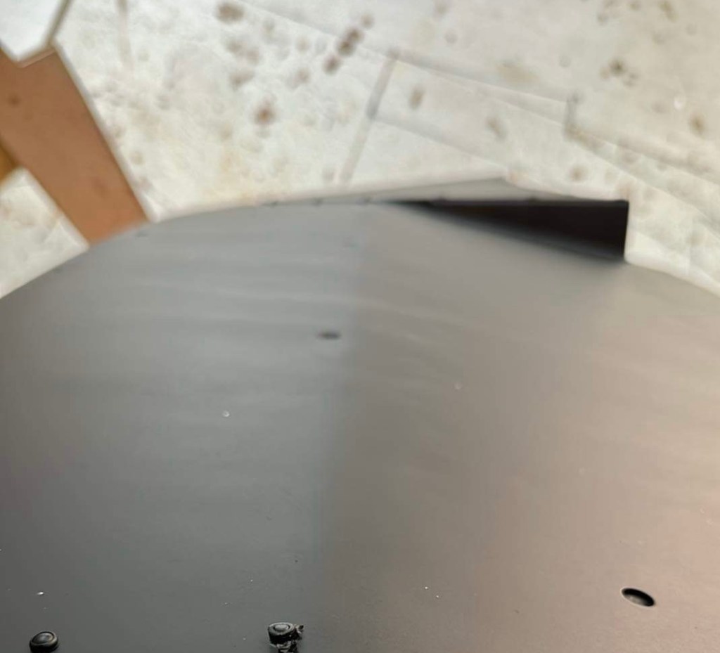
I then cut out the general shape and drilled the mounting holes. To create the curve of the diffuser, I clamped the aluminum down to the table and alternately leaned on it and tapped with a hammer to create a curve. It looks like a single bend in the picture, but it’s actually three bends, with a gradual radius.
Diffuser kick is gradual.
There are little aluminum ramps, sort of a Z-plate, that connect the flat portion in front of the wheels to the curved section in the middle. You can see those little triangles in the previous (blurry) image. These are fastened with rivets.
Aluminum signs riveted together.
I guessed at the shape and length of the diffuser, and guessed wrong. It took a few tries to get the shape of the trailing edge, because the oil pan and intake plumbing are in the way. While doing that trimming, I also decided to add a hole for oil filter access. I later taped over this, and so accessing the oil filter is as simple as removing the tape.
Final shape of undertray, compared to OE.
The undertray attaches at the OE mounting points, but I replaced the plastic pop fasteners with 6mm speed clips. I used long countersunk Allens for the four bolts that attach to the radiator bracket. It’s fuggin solid.
How will it work? It’s hard to say, but I’ll make a guess. A flat splitter was 132 lbs of downforce at 100 mph, while the curved splitter was 163 lbs. So the diffuser portion alone might be 30 lbs of downforce, and when coupled with the differential in front pressure… let’s call it 60 lbs of downforce.
Splitter curvature (and/or vortex strakes) also contributed to a significant reduction in drag (.019) that resulted in a gain of about 3 hp vs the flat splitter. So the diffuser undertray may have some drag reduction, as well.
As DIY projects go, this was a satisfying one. It cost me $10 in materials and was finished by lunchtime. It weighs only 2.5 lbs more than the OE plastic, and is just as unobtrusive. The diffuser likely confers a performance benefit in both downforce and drag, and would probably pass scrutiny for a street (unmodified) class. I’ll take that as a win.
There are some racing rules that specify a flat splitter, but say nothing about the undertray (SCCA STU, for example). A clever person could add a flat splitter in front of this type of undertray, and get the full benefit of a fully curved splitter, while also adhering to the written rule. Likewise, there are some racing rules where a splitter costs some performance points, but you can add an airdam and (unspecified) undertray for less. Undertray diffusers FTW!
In a previous article I covered Miata fender vents in some detail, including commercially available louvers and DIY solutions. I cited Race Louvers wind tunnel data, which found that after a certain size, more vents don’t equal more downforce. What I didn’t mention was the reason for those diminishing returns.
All of this venting is overkill unless you can reach further inside the wheel well.
Take a look at a Miata unibody with the fenders removed, and you can see the problem. At the top of the fender, vents can reach just about the width of the tire, but the air has to travel all the way up there in order to be extracted. A more direct route is behind the tire, but the chassis is in the way! Moreover, air needs to take a 90-degree turn to make its way out of the wheel well. On a Miata, there’s a sharp lip here where two seams come together, which makes it even harder for air to turn the corner.
Naked Miata shows the crux of the problem.
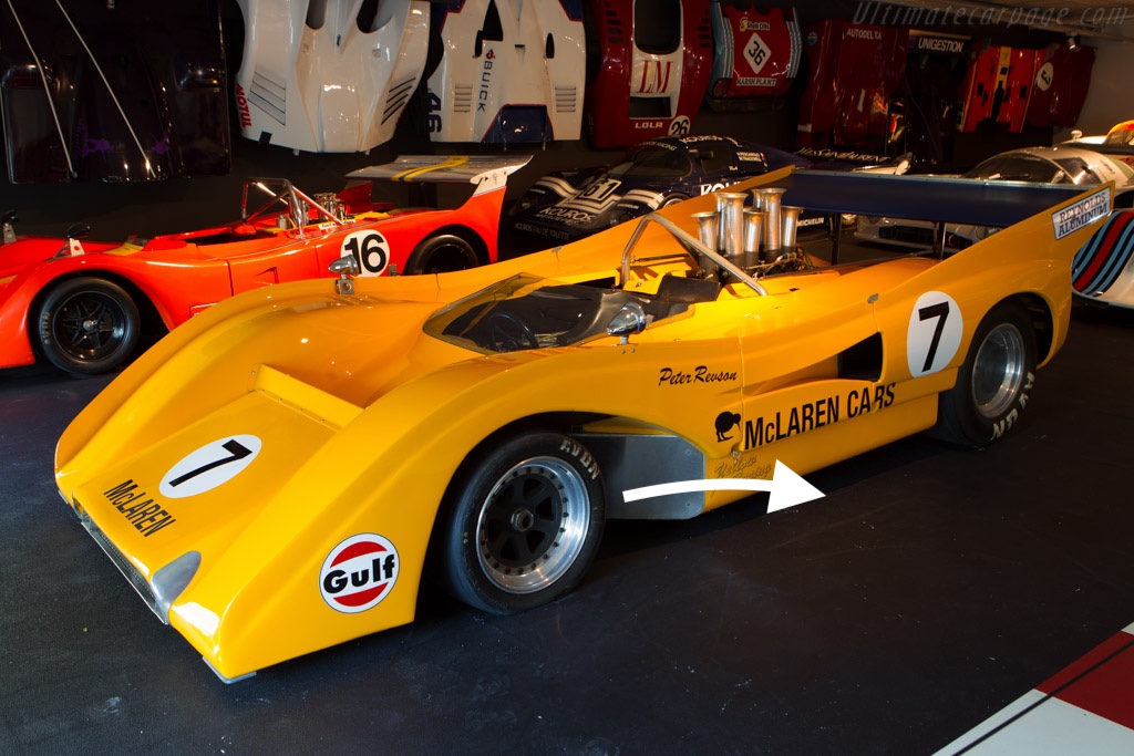
In order to extract more air, the vents need to reach further inside the wheel well. Ideally the vent should be located low and behind the tire, because that’s the most direct exit route from the trailing edge of the splitter. And while doing that, you’d also design a much smoother exit. The end result would be quite different than the haphazard dumping and venting of air into the wheel well, and more of a purposeful and free-flowing duct from splitter diffuser to behind the wheel. Now these aren’t new ideas; you can see all of that on a McLaren M8 from half a century ago.
McLaren M8 had big vents and smooth exits back in 1971.
A more subtle solution can be seen on the underside of current NASCAR stock cars. Notice the air channels behind the tire that exit at the front of the rocker panel. This allows the cars to look stock-ish, but they perform much better and make a lot of downforce. In fact too much downforce, because NASCAR had to reduce the effectiveness by adding splitter stuffers.
NASCAR underbody aero was so effective they required splitter stuffers (the black horizontal bars in the splitter diffusers) to reduce front downforce.
I don’t know if these vents have a proper name, but I’m going to call them rocker vents based on their location in the rocker panels. They are a very Occam’s Razor solution to extracting air from under the splitter; of the myriad ways you might solve the problem, rocker vents are the simplest. Well, at least from the perspective of air, it’s the most direct route.
I wanted to implement something like the NASCAR rocker vents on Falconet, but hadn’t seen anyone else modify their Miata in such a manner. AJ Hartman did something like this on his Mustang, and said it was very efficient, with a L/D of 14:1.
So I knew it could be done, I just didn’t know how to do this on a Miata. I did a lot of exploratory cutting on the driver’s side, and the pictures show how I did a much cleaner job on the passenger side.
I want to thank Aussie reader/supporter Jim Grant for assistance with this project. He recognized I had no idea what I was doing and explained how cars are put together, and how to get my head out of my ass. Thanks Jim!
Step 1: Measure
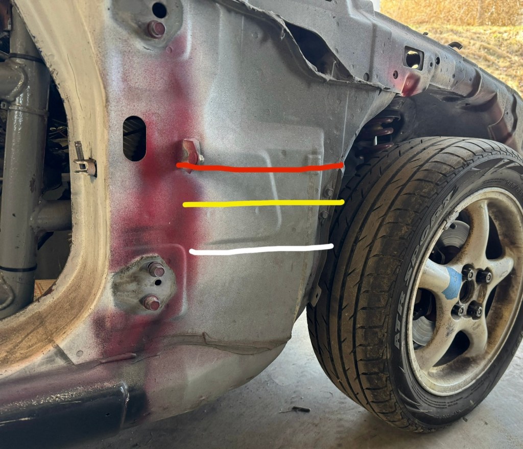
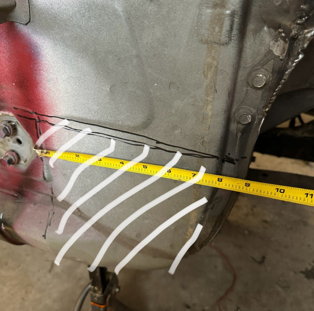
My first decision was how large (height and depth) to make the vent. There are a few considerations for height, see the following image with colored lines.
Three logical places to cut.
The white line is the most conservative cut, because it goes just below the curved wheel tub inside the wheel well. Cutting at this height leaves two threaded holes intact, in case you want to add bolt-on fender braces.
The yellow line is about where the mid-body style line is on a NA Miata. Aesthetically, this is probably the best place to cut a NA Miata, but on a NB it wouldn’t matter. This cut goes between the two bolt holes, and so you could still use the upper hole to mount something.
The red line is to the top of the wheel tub. You could go higher than the red line, but most of the air you’re trying to extract is below the splitter, so I’m not sure if a higher cut helps that much. Might look cool tho.
Bring that rocker vent all the way to the top and it might look like a RX-7 GTO. Fucking badass.
In retrospect, if I did this again, I’d cut on the yellow line. Mostly because I think it would look better to have the duct exit on the style line. I don’t know that there’s a lot more air to extract at that height, and it could be that a vent even half this high is just fine (the NASCAR vents are quite low). In any case, I used the white line.
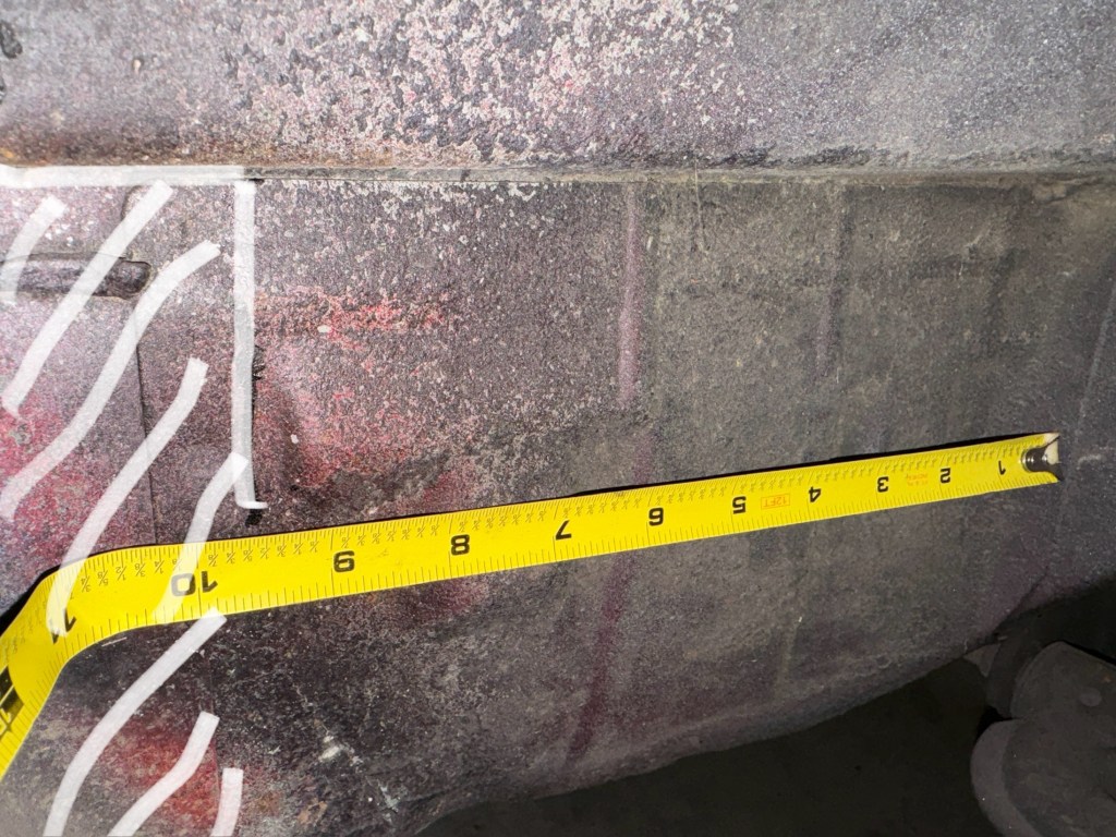
The next decision is how deep to make the cut. I measured and marked a line 9.5” from the inside of the wheel tub. This is where the inner sheet metal is located within the footwell, and so the cockpit remains unmolested.
I removed the white crosshatch area, it starts about 9.5” from the inner wheel well.
The rocker vent would be more effective if I had cut further inside behind the wheels, but then I’d need to weld sheet metal inside the cabin. Going further than that, there’s other unibody structure and cage tubing that would be difficult to work around. If I’d kept going deeper, I’d hit the clutch dead pedal, which could be sacrificed I suppose, but I do use it.
All said, I chose to make the rocker vent only about 3” (75mm) deep. This isn’t a lot of extra volume, but it does allow air to exit at less of an angle.
I used a sharpie to draw a line back to the hinge at my desired height. I’m not going to use the lower hinge (my doors are only half height), but there’s a vertical chassis member here and I wanted to keep that intact. So at this point, I have defined the area I want to remove.
Take a minute to pause and question if you’re really going to do this.
Step 2: Surgery
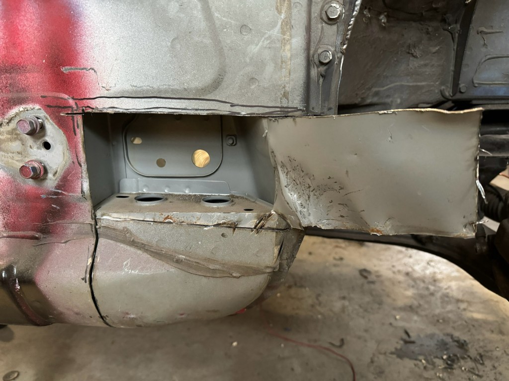
I used a grinder with a cutoff wheel to cut along the lines. There’s a horizontal shelf inside that has to be removed. It’s spot welded in various places (you can see the dots) and I tried drilling those out and in some cases getting in between with a cold chisel and breaking the welds. This little shelf is a pain in the ass.
Cut an opening so that you can remove the shelf.
I continued to cut out all of the sheet metal and spot welds until I had a rectangular-ish hole like this.
The point of no return. Or, what the fuck have I done?
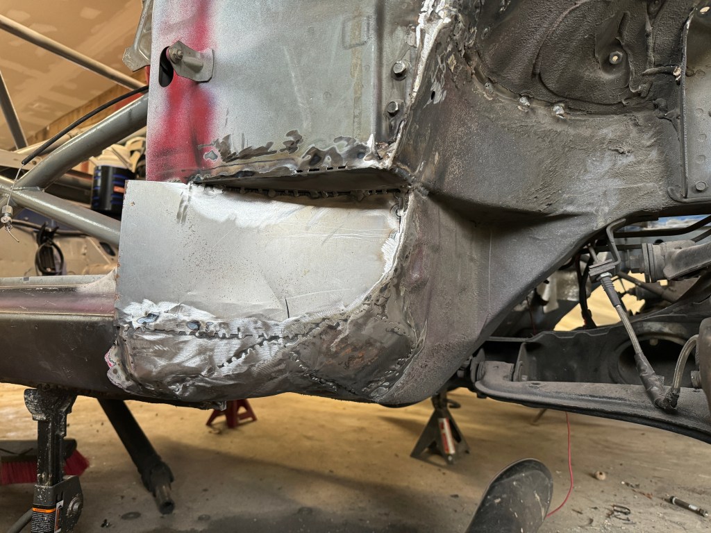
The interior footwell and exterior wheel tub are two pieces of sheet metal with an air gap between them. I used a cutting wheel to make a slit in this area, and then used a reciprocating saw to cut out the sheet metal. I ended up with a cavity or “smile” between the interior footwell and the fender well.
Cut out all the sheet metal between the footwell and the wheel tub.
To get a smoother exit for air, I used a cut off wheel to cut several straight lines through the bottom sheet metal. I then bent the sheet metal upwards to close that gap.
Slits make it easy to bend the bottom upwards.
I used a hammer to tap these into a more graceful arc.
I should have cleaned off all that gunk with a wire wheel before starting. This needs to be bare metal for welding.
I then cut the front of the rocker panel off at an angle, so that air can make less than a 90-degree exit. Notice the rocker panel is made of a few layers of sheet metal, and plays a significant role in chassis structure and stiffness.
Front of rocker panel cut at an angle.
Next I’ll weld in some sheet metal to cover all this ugliness, and provide a smooth path for air to flow.
Step 3: Welding
Welding Mazda sheet metal kinda sucks. I was once a certified structural welder, but you’d never know looking at the shit job I did on this. I got the best results by spot welding pieces together, and then joining some of those to create stitches. Note that continuous welds are unnecessary, as you can fill the gaps with seam sealer.
First step was to bend in a piece of sheet metal to make a smooth curve, and then cut it to size.
Nice curve.
Next I welded in a horizontal flat that makes the ceiling part of the vent. Otherwise there would be an open cavity that might collect gunk inside. I welded that to the curve I had cut.
The ceiling of the vent.
Next I welded the tabs I cut in the footwell area, that I had bent upwards with a hammer. I ran a cutoff wheel into the overlapping pieces of metal and pulled the little triangles out, then smashed it all flat again. This way the seems were pretty tight and easy to weld inside and out.
Bend tabs up, close the gaps, and weld.
Now the fun part, bending sheet metal into curves and tacking it into place. I used aviation shears to cut sheet metal into various shapes, and then tack welded it all together. This process is more art than science, and satisfying work.
Small pieces of sheet metal can be bent and spot welded to make easy curves.
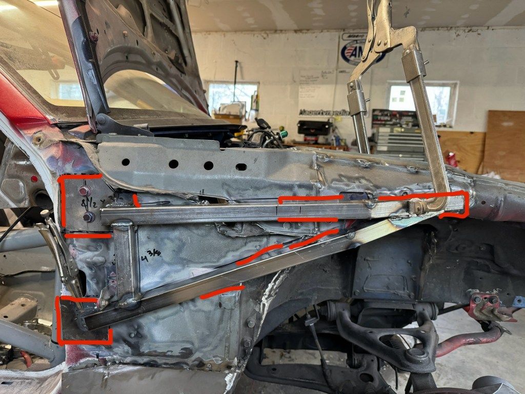
The next step was to add external bracing to the shotgun panel (the frame member that connects the door hinge area to the shock tower). There are several commercially available fender braces, but I chose to DIY my own and weld it on rather than use bolts.
DIY fender brace and welding spots.
I used 1” square tubing and 1/8” steel spreader plates to make a triangular brace. Weight weenie that I am, I was pleased they only weighed 3 lbs apiece. I then welded the braces in several spots, choosing places where the sheet metal overlapped and was doubled in thickness. I also seam welded the entire front of the chassis for good measure.
Front view shows the 3” (75mm) of extra depth cut inside the wheel well, and rounding underneath and at the exit.
I ordered a new set of fenders, which I’ll cut artfully to expose the rocker vents. In the meantime, I took my existing fenders, which have a large fender cut, and mounted them up to see what this all looks like.
When looking at the rocker vent from the rear, you can see that air will exit much lower and smoother behind the wheel. No more 90- degree bend or having the air exit between the chassis and the quarter panel.
Big vent with a smooth exit will help the splitter make more downforce, and should cool the brakes as well.
Step 4: Finish
The final steps are to fill the gaps between the spot welds with seam sealer (automotive caulk). I have also heard that you can fill the rocker panel and front cavities with expanding foam, which supposedly adds more rigidity. I don’t know that expanding foam from a can (Great Stuff) is appropriate for this, but it would certainly be easy to do.
I’m not going to cover the rocker vents with quarter panels; the area will be entirely exposed. So it needs Bondo, primer, and paint to match the bodywork. I haven’t done all that yet, but it’s just regular bodywork, and I’m the last person you want to watch do that.
When that’s done, I’ll also add some vanes under the car. I’ll take my inspiration from NASCAR again, and guide the air out the new rocker vents with a pair of strakes.
Wind tunnel test?
I’ll add strakes like these red ones.
To find out how much downforce and drag the rocker vents make, I’ll fabricate rigid covers that approximate the shape of the original bodywork. I’ll then remove the covers and A/B test the vents back to back in the wind tunnel.
The A2 wind tunnel has a static floor, and so it’s not as accurate as one with a vacuum to remove the boundary layer, or a rolling floor. So while the numbers won’t be 100% accurate, there will be a useful delta value, and a way to compare the rocker vents to other vents.
Caveats aside, I’ll update this article with those results sometime after 6/20.
Now it’s your turn
If I’ve inspired you to make rocker vents, consider the following:
First, do you really need rocker vents? A splitter alone makes enough downforce to offset a low-angle single-element wing. Add splitter diffusers and vent the fenders, and you may get another 50% more downforce. Add spats, side plates and canards, and you could double the original splitter’s downforce. At this point you’ll almost certainly need maximum wing angle and a Gurney flap, and even then the front aero load distribution may be too high (oversteer in fast corners).
But if you’ve already done all the tricks and still need more front downforce, then the rocker vent is perhaps the next step. But you’ll probably need to add some combination of spoiler, second wing element, and rear diffuser.
On the other hand, maybe you’re not after maximum front downforce and are simply after better efficiency, or maximizing the effectiveness of the undertray. Or perhaps you’re dodging the points taken for using a splitter, but you want similar downforce. That’s a pretty clever use of rocker vents, and I would definitely get on board with any of that.
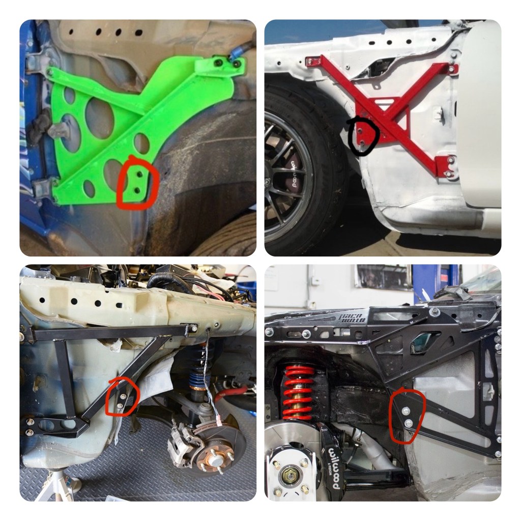
Next question, do you have a full cage? You’re removing important structure from the unibody and a full cage is arguably a requirement for rocker vents. Without a cage, you’ll need fender braces or other supports that help support the shock tower (no, not a strut tower brace).
As a practical matter, most commercially available Miata fender braces use the two threaded bolt holes in the wheel tub for mounting, and the location of those bolts limits the size of the rocker vent. If you recall the previous image with the horizontal lines, you’ll want to cut on the white line, or lower.
If you make rocker vents, you’ll need a full cage and/or fender braces. Some bolt-in solutions shown.
Final question, if you’re racing, do your rules allow modifying the unibody structure? For any Spec racing series, that answer is certainly no. For other series, it will depend on how they evaluate such modifications.
I’m building Falconet to the NASA ST/TT 3 rules, and changes to the unibody require the “non-production chassis” mod, which is a .4 points penalty to the lbs/hp calculation. If I was building to the NASA ST/TT 4-6 rules, then this modification would be illegal, as the rules state you can’t alter the unibody.
My car also fits into SCCA Time Trials Unlimited 2 class, and this would be legal. But not in any of the Max classes (in fact Falconet isn’t legal in Max for other reasons as well).
I didn’t look up the SCCA road racing rules because it’s a 1000 page rule book. Nor did I look at the 400 page autocross rules, because this is an aero mod, and unlikely to help much at 40 mph. But there’s probably some flavor of unlimited class my car would fit into if I wanted to roadrace with the SCCA or dodge cones in a parking lot. (I don’t.)
Most of the Grid Life Trackbattle classes state that you can’t make modifications to the chassis, and that includes GLTC. But you should be able to get away with rocker vents in Street Mod, Track Mod and the Unlimited classes.
Most endurance racing rules would allow rocker vents, and with their high efficiency, it would be a good idea for AER, 24 Hours of Lemons, Lucky Dog, Northeast GT and WRL. Champcar would assign material points (2 points per square foot of metal), and that might be 4 points total. But a clever team could reuse sheet metal taken from various weight loss trimmings and/or use the lower quarter panels and do this mod for free.
If you aren’t racing or tracking your car, one could argue that rocker vents are a lot of work for Racing Inspired Cosmetic Enhancement (RICE). But if that’s the way you roll, you’ll one up everyone else’s fender vents at the local cars and coffee.
All told, this project cost me maybe $40 bucks in materials (8 feet of 1” steel tubing, welding wire and gas), so if you have more time than money, I say why the fuck not? So now it’s your turn. Let’s see some rocker vents!
As someone who is building a car to fit into multiple racing classes, I need to keep up with the aero rules in different series. It’s important to know not only what is allowed in each class, but how various aero components are weighed vs other performance modifications. I gave a broad overview of several aero rules in Aero Rules… but OMG the Fecking Rules!, but wanted to dive deeper in one area.
Through this journey, I’ve leaned that most rules are written by people who have a Childs understanding of car aerodynamics. That’s not a typo; let me explain.
I used to read the Jack Reacher series of novels by Lee Childs, and in every book the author would make a dumb technical error relating to firearms. I know firearms because I was a nerdy reloader for several years, and in this field, where things can literally blow up in your face, as Jack Reacher would say, “details matter.”
As a character, Jack Reacher understood this, but his creator did not. After the author incorrectly referred to a trio of Thompson submachine guns as “grease guns” I emailed Lee Childs and said that while I enjoyed his writing, he needed a technical editor. I offered to copyedit his next book for free.
Not the same.
Note #1: The M1928A1 “Tommy gun” and M3 “grease gun” fire the same ammunition and perform the same role, but they look nothing alike and even someone who knows nothing about firearms wouldn’t confuse the two. I mean, one of them looks like a tool for squirting out grease, the other one is in gangster movies.
Note #2: Writing the author directly and offering my services may seem like a bold move, but this is exactly how I became a globe trotting motorcycle journalist for Moto-Euro magazine.
I wasn’t surprised when I didn’t receive a reply from Mr Childs. And so I also wasn’t surprised when he fumbled again in a later book referring to to a rifle as a “M14 Garand”. <sigh>
There’s no such thing as a M14 Garand. I own a M1 Garand, and I’ve shot a civilian M14, and while they are similar rifles, they don’t even use the same cartridge. Calling a rifle a “M14 Garand” is as idiotic as saying that Reacher’s new car is a “Mustang Corvette.” Yes, it’s that stupid.
To make matters worse, in the same story Reacher gets a ride from a woman in an enormous pickup truck. Astounded by the size of the truck, Reacher notes that it’s a Honda. Come on now!
Honda doesn’t make an enormous pickup truck, and now I was certain about two things: Childs knows as much about firearms as he does trucks. These are man’s-man topics, as baked into Jack Reacher’s DNA as the fisticuffs he engages in. After these two gaffes I let out a guffaw and could no longer read anything from that charlatan.
Let’s bring this back to aero rules. It’s difficult to write a racing rulebook, it takes the input of specialists with specific knowledge on suspension, tires, safety, engines, and aero. For whatever reason, rulebooks, like the Reacher books, get published with a Childs understanding of aero. And this results in some silly rules.
Of all the nonsensical rules I’ve seen, from banning fastbacks on convertibles, to equating wings with spoilers, to allowing diffusers but not flat bottoms… the most Childs-like rules are the splitter rules.
Flat splitter nonsense
Splitters separate the air above and below the splitter blade. They create downforce via a high pressure zone on top of the splitter blade, and a low pressure zone below it. You know what else creates downforce in the same manner? A wing.
Just like a wing, a splitter creates much more downforce through suction than from pressure. You can vastly improve the performance of a splitter by adding camber. Most people do this by installing splitter diffusers (splitter ramps), which add curvature over a small area in front of the wheel wells. Time attack cars often curve the entire rear of the splitter’s trailing edge upwards, thereby creating a splitter diffuser across the full width of the car. And some cars also curve the front upwards as well.
However you do it, adding curvature creates a Venturi, accelerating air under the lowest part of the splitter. This in turn drops the pressure, resulting in suction and downforce.
Given that this is how a splitter works, it’s surprising how many rulebooks specify that a splitter must be flat (or horizontal, or without curvature). A rule that states that a splitter must be flat is akin to a rule that states that a wing must be flat! I think we can all agree just how well a wing like that would work.
Class legal; shit performance.
Splitters without side plates
Because splitters behave similarly to a wing, they also benefit from some attention paid to the outer edge. Look at any wing and you’ll see end plates. Look at any pro-level race car with a splitter, and you’ll see various things on the end of the splitter, which I’ll collectively refer to as side plates. These devices trap high pressure air, change the stagnation point, promote extraction, or in other ways improve the splitter’s functionality.
If there’s room on the end of your splitter blade, side plates are a no brainer. And yet, how many racing rules state that splitters can’t have anything on the ends of them? Many of them! Just for fun, I’ll pick on the SCCA autocross rules:
Front splitters are allowed but must be installed parallel to the ground… The splitter must be a single plane with the top and bottom surfaces parallel… A front splitter and its associated features shall not function as a diffuser… Splitter fences or longitudinal vertical members that serve to trap air on top of the splitter by preventing it from flowing around the sides of the car are not allowed.
You see the same verbiage from NASA, SCCA road racing, and numerous other club racing rules. Given that the splitter rules don’t allow side plates, I find it surprising they allow wings with end plates. I mean, it’s the same damn thing.
Splitter width and length
Time attack cars don’t race wheel to wheel, and so rear wings and front splitters are often much wider than the car. For example, in the Global Time Attack rules, in the Limited class, you’re allowed to use a splitter that extends 10″ in front and is 14” wider than the body.
Looks like it could fly.
On the other hand, most wheel to wheel racing rules limit the span of wings and splitters to body width. This is understandable, as you don’t want aero parts to hit each other on track. However, there’s no standardization on the length of the splitter lip. When you consider how few racing rules mention the chord of a wing, it’s amazing how many rules there are on splitter length. Again, this is the same thing! Here’s a smattering of splitter lengths:
12” Champcar
6″ – NASA ST1-ST4
5″ – SCCA Time Trials Nationals, SCCA GT1, GT2
4″ – NASA ST5
3″ – Grid Life Touring Cup, SCCA STU
2″ – SCCA STO, GT3, Super Touring, T1
0″ – SCCA Street Prepared
I’ll make fun of the SCCA autocross rules one more time, because it’s such low-hanging fruit. Did you see that last item on the list? The SCCA autocross Street Prepared rules allow you to have a splitter, but it can’t stick out past the bumper. Here’s the exact wording:
“A spoiler/splitter may be added to the front of the car below the bumper. It may not extend rearward beyond the front most part of the front wheel well openings, and may not block normal grille or other openings, or obstruct lights. Splitters may not protrude beyond the bumper. “
WTF? You can have a splitter but it can’t protrude beyond the bumper? How is that possible? Perhaps when this rule was written (1973?), all cars had underbite bumpers, but show me a modern car that you can fit a splitter to that doesn’t extend beyond the bumper!
You could fit a splitter to the Mustang Corvette on the left, but not on the right.
I don’t want to just pick on SCCA autocross rules, because splitter rules across most car racing rulebooks show a misunderstanding of how splitters work. Whoever is writing these splitter rules could have easily written the following rule for wings: “Cars may use a rear wing, but the wing must be completely flat, installed horizontally to the ground, and with no curvature. Vertical members that serve to separate air above and below the wing are not allowed.”
I’m curious, who was the first rules lawyer that decided to castrate splitter performance? I feel like they have a lot to answer for. Some may argue that cost cutting is the reason, but you can make splitter diffusers and side plates for $10. Heck, you can make a fully curved splitter for free by selecting a warped piece of plywood!
But in the end, I guess it doesn’t matter who started this, because virtually every other rules writer copied and pasted the same absurdity into their rulebooks. That’s on all of them for having a Childs understanding of aerodynamics.