I look at airfoils a lot, comparing different shapes at various speeds and angles of attack. It’s a nerdy and pointless exercise, because Miatas are limited by front downforce; trying to get the most out of the rear is rarely necessary.
Of the commercially available wings, 9 Lives Racing’s extruded aluminum wing is the best bang for the buck, and nobody is going to feel bad about that purchase. The Big Wang is built apocalypse-strong, and you could probably run a front wing as a bumper. With that strength comes weight, and that’s the only nit I have to pick.
At .2 lbs per inch, a Miata-sized 64” wing weighs 13.2 lbs, and when you add wing mount and end plates it’s close to 20. This isn’t all that much weight considering the benefit you get, so what am I fussing about?
It’s where the weight is. Put that weight down low in the center of the car, and it wouldn’t matter. But put that weight at roof height, at the far end of the car, and that hurts fast changes of direction.
Try this: Imagine running around your yard like it was an autocross track, holding a broom out in front of you. Now do that again with the broom held close to your chest. Much easier! Mass centralization is important for fast changes of direction, and weight at the polar ends of the car, or high up, is bad.
I race a time trials series at Pineview Run, which is a very tight road course with 15 turns in one mile. It’s a bit like an autocross course, but with elevation and camber changes. With so many fast changes of direction, I’ve had better results with a spoiler than a wing. Mathematically, the wing is making more downforce and I should have more grip than when using the spoiler. But the stopwatch doesn’t lie, and I believe the reason for that is entirely the weight and location of the wing.
So I got to thinking about it, and I figured I could build a lighter wing. I’d also make it narrower, which would help a little for mass centralization. But I’d need to increase the chord to so that it had similar overall downforce.
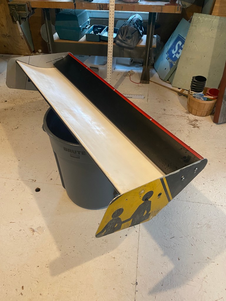
I started with the 9 Lives Racing “Mini Wangs“, which are cutoffs from their factory. I traced the 9LR wing profile onto two pieces of 1/4” aluminum plate, and cut them out on a band saw. I then drilled one side of the Mini Wangs and tapped them for a M6 bolt, and drilled through the other. Next I simply bolted them together. These would serve as my wing supports, as well as the support for my end plates. No welding, easy peasy, and someone could easily do the same upside down and make a swan neck mount.
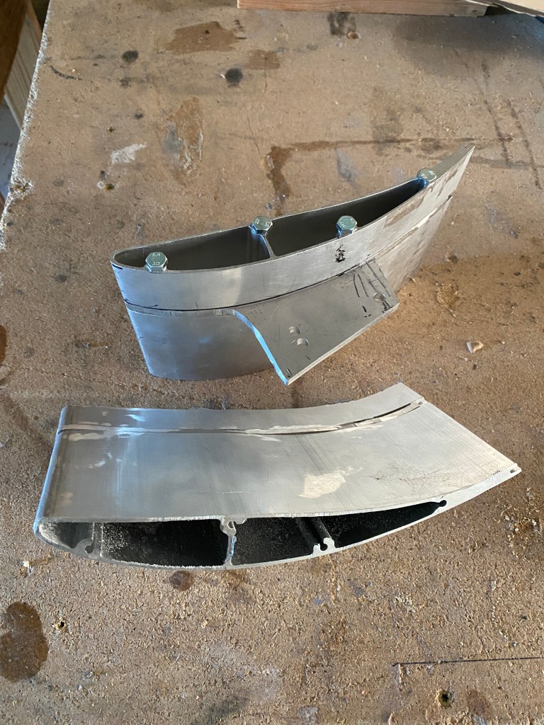
Next I took a strip of 48″ of aluminum (street sign) and bent an angle on it. This made a 2.5″ extension that I wedged into the 9LR Gurney flap slot. (I had to cut the vertical part of the slot off.) This would act as both the Gurney flap and the chord extension. I used the extension/flap to join the two “book ends” I’d made, and added a center support using another 9LR Mini Wang. For the nose of the wing, I used 1/2″ aluminum tubing, fastened into the bookends and center mini wang.
Next I took a skateboard laminate (single ply of maple that bends easily and takes epoxy well, and I happen to have a lot of these around because my buddy Jason owns Comet Skateboards) and epoxied it over the underside of the wing. I strapped the whole thing down with clamps and let it cure.
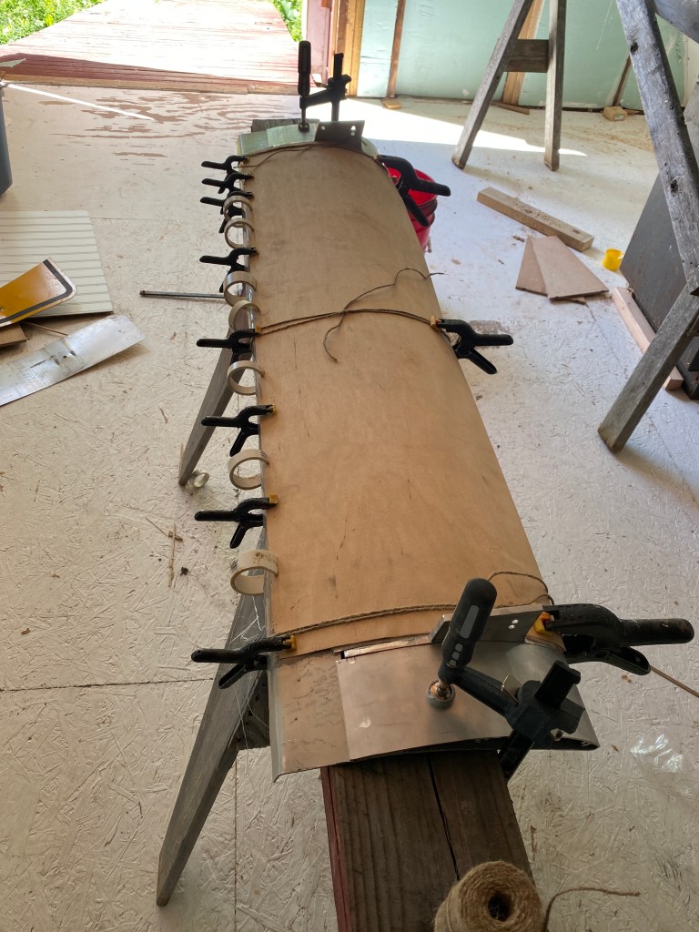
Then I flipped the wing over, added some supports on the inside, and glued another skateboard laminate to the top. I then fiberglassed the whole thing with 6 oz fabric.
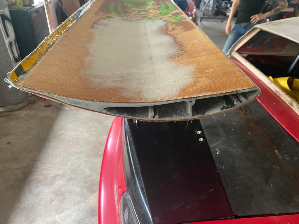
The end result is a 9LR wing with more chord. Ideally I would have made it slightly thicker (to preserve the same shape airfoil), but cut me some slack here; I’m literally gluing a skateboard deck and a street sign to scrap metal.
All told this wing cost me about $70 in materials and a few evenings of labor. But I have a lot of experience with fiberglass and weird shit laying around (like Comet skateboard laminates, street signs, microballoons, etc.), and someone else buying all the materials and having less experience would double the cost and effort.
One Louder
I was trying to come up with a name for the wing. It measures over 11”, which reminded me of the quote from Spinal Tap, “this one goes to 11.” So I’m calling it the Marshall wing, after the guitar amp.
The Marshall has 9% less area than the typical 64″ 9LR you’d put on a Miata, and should have about the same amount of downforce as a 58” 9LR wing. I used a 60” wing on my fastback Miata, so that’s in the same ballpark.
However, at 48″ wide, the ends of the wing are not in free-stream air, and the close proximity of the wing stands and end plates is going to cause more drag and probably some loss in downforce to turbulence. My guess is that behind a standard Miata hardtop, this wing will make 15% less downforce than a regular 9LR wing. Mounted behind my fastback, it’ll be fine.
The important part is that the Marshall weighs just 7 lbs, including the beefy 1/4” wing mounts. This is about half of what a 64″ 9LR wing weighs, and that was the point of this project.
End Plates
If you’ve read my article on DIY end plates, you know that end plates are about the least important thing you can optimize on your car. A good rule of thumb is to make the end plate rectangular, and about as deep as the chord.
I made these end plates from a 10 MPH street sign. I started with a rectangular shape that would leave a number 10 on one side, and the initials MPH on the other. I rounded the bottom corners so I won’t cut my head open reaching for a tool under the car. I made a relief cut on the top to bleed some high pressure air on top of the wing and reduce drag, and then made a cut on the top back corner to lessen the vortex there.
But the real reason I chose this end plate shape is simply to preserve the serif on the number 1. This is how much I care about end plate design these days, I’m letting the sign graphics dictate the shape.

Double Wing – Marshall Stack
My single-element Marshall wing should work for high speed tracks where a reduction in drag might be useful, but I really made this for Pineview Run, where the average cornering speed is in the 40s. For that speed, I could use maybe even more chord and more camber. The easiest way to do this is to stack a second element onto the existing wing. That’s right, I’m calling this the Marshall Stack!
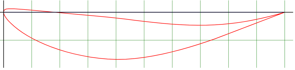
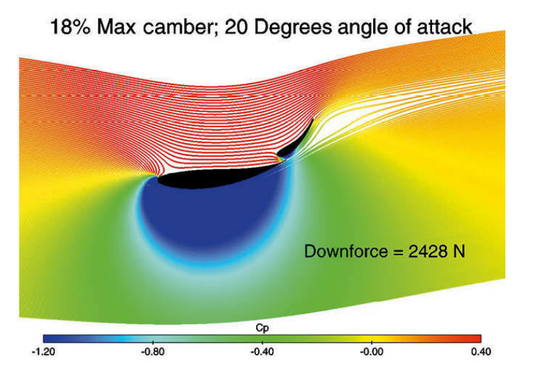
I have a couple made-in-China wings kicking around my shop. I’ve modified the bottom profile to fill in gaps and add roundness, and it’s now a custom profile. I went looking for a similar profile on Airfoil Tools, and the closest I can find is the WORTMANN FX 72-MS-150B shown here at zero degrees. I reviewed that wing in a previous article, no need to go into the details here.
Gurney Flap and End Plates
I want to put a Gurney flap on the upper blade. On airplane wings, the standard formula for Gurney flap height is 1-3% of the chord, but on cars you typically see 5% and even up to 10%. The MIC wing has a 5.6″ chord and 5% of that is .28″ which is close enough that I’ll call it 1/4″.
I can adjust the main and secondary wing angles, so I don’t think it’s necessary to have a removable Gurney flap, so I riveted 1/4″ angle aluminum to the top of the wing and called it done.
You may recall that the main wing already has a Gurney flap, it is in fact an integral part of the entire wing structure! But can you use a multi-element wing with Gurney flaps on both wings? Yes. I’ve read a couple scientific papers (1, 2) on the subject, and it definitely creates more lift, but it’s finicky.
There is risk of turbulence and flow separation at the main wing’s Gurney flap, and this appears mostly dependent on the size of the convergent gap between the wings. Which is also dependent on the size of the Gurney flap. To quote Catalano “The use of Gurney flap at the trailing edge of the main element is highly dependent on the gap and overlap optimization.”
To hedge my bets I did two things: First I reduced the size of the main wing Gurney flap to 2% of the chord (about 1/4″); Next I drilled two sets of adjustment holes in the end plates, one to create a smaller convergent gap, and one for a larger gap. I can now adjust the gap size vertically and see which works better.
The secondary wing is supported entirely by the end plates. I made some new ones from street signs following MacBeath’s pressure plot of a double wing.
To cover the low pressure zone, you can see that the end plate doesn’t need to be extend aft of the upper wing. Most of the low pressure (suction) zone is low and in front of the main wing. My rule of thumb is to make end plates as deep as the chord of the wing, but when I mocked them up, it just looked stupid. I know that larger end plates would probably perform better, but sometimes you have to make concessions for appearances.
MacBeath and others have suggested 2nd element angles of between 20-40 degrees, and so I drilled three holes to allow 10-degree increments on the upper wing.
Triple Stack?
Using another MIC-wing and street-sign end plates, I added a third wing on top. I tested it at Pineview and it worked even better than the double stack. But it looks so fucking ridic I’m embarrassed to be seen with it in public.
But this construction method proved strong and light, and my next project is a 3D wing for my Veloster N. Subscribe to the blog if you want an update when that happens.

Kudos on the Marshall Stack materials, design and execution. I recently switched from a spoiler to a dual element wing for my AutoX RX7. Before building it, I did tuft testing at 55 mph over the quarter panels (IMSA GTU flares) and the deck glass to define the airflow angle at the height of the leading edge of the wing. The deck airflow was negative 13 degrees. Thus, the middle element is staggered from the outboard elements. After installation, I did more tuft testing at 55 to see if the air was attached to the backside with the gap that I had selected (TLAR at 0.35 inches). The flow was attached. I’d be interested in what you find out from testing the two gaps on your design. FWIW, the cornering G’s went from 1.5 to 1.65 on the courses we have (avg about 45 mph). Also, the attached flow begins at 25 mph.
Thanks for sharing your efforts.
R
LikeLike
Wow, that is some great testing and data, and some really positive results. 1.5g to 1.65g at that speed is fantastic, well done!
LikeLike