As someone who is building a car to fit into multiple racing classes, I need to keep up with the aero rules in different series. It’s important to know not only what is allowed in each class, but how various aero components are weighed vs other performance modifications. I gave a broad overview of several aero rules in Aero Rules… but OMG the Fecking Rules!, but wanted to dive deeper in one area.
Through this journey, I’ve leaned that most rules are written by people who have a Childs understanding of car aerodynamics. That’s not a typo; let me explain.
I used to read the Jack Reacher series of novels by Lee Childs, and in every book the author would make a dumb technical error relating to firearms. I know firearms because I was a nerdy reloader for several years, and in this field, where things can literally blow up in your face, as Jack Reacher would say, “details matter.”
As a character, Jack Reacher understood this, but his creator did not. After the author incorrectly referred to a trio of Thompson submachine guns as “grease guns” I emailed Lee Childs and said that while I enjoyed his writing, he needed a technical editor. I offered to copyedit his next book for free.
Not the same.
Note #1: The M1928A1 “Tommy gun” and M3 “grease gun” fire the same ammunition and perform the same role, but they look nothing alike and even someone who knows nothing about firearms wouldn’t confuse the two. I mean, one of them looks like a tool for squirting out grease, the other one is in gangster movies.
Note #2: Writing the author directly and offering my services may seem like a bold move, but this is exactly how I became a globe trotting motorcycle journalist for Moto-Euro magazine.
I wasn’t surprised when I didn’t receive a reply from Mr Childs. And so I also wasn’t surprised when he fumbled again in a later book referring to to a rifle as a “M14 Garand”. <sigh>
There’s no such thing as a M14 Garand. I own a M1 Garand, and I’ve shot a civilian M14, and while they are similar rifles, they don’t even use the same cartridge. Calling a rifle a “M14 Garand” is as idiotic as saying that Reacher’s new car is a “Mustang Corvette.” Yes, it’s that stupid.
To make matters worse, in the same story Reacher gets a ride from a woman in an enormous pickup truck. Astounded by the size of the truck, Reacher notes that it’s a Honda. Come on now!
Honda doesn’t make an enormous pickup truck, and now I was certain about two things: Childs knows as much about firearms as he does trucks. These are man’s-man topics, as baked into Jack Reacher’s DNA as the fisticuffs he engages in. After these two gaffes I let out a guffaw and could no longer read anything from that charlatan.
Let’s bring this back to aero rules. It’s difficult to write a racing rulebook, it takes the input of specialists with specific knowledge on suspension, tires, safety, engines, and aero. For whatever reason, rulebooks, like the Reacher books, get published with a Childs understanding of aero. And this results in some silly rules.
Of all the nonsensical rules I’ve seen, from banning fastbacks on convertibles, to equating wings with spoilers, to allowing diffusers but not flat bottoms… the most Childs-like rules are the splitter rules.
Flat splitter nonsense
Splitters separate the air above and below the splitter blade. They create downforce via a high pressure zone on top of the splitter blade, and a low pressure zone below it. You know what else creates downforce in the same manner? A wing.
Just like a wing, a splitter creates much more downforce through suction than from pressure. You can vastly improve the performance of a splitter by adding camber. Most people do this by installing splitter diffusers (splitter ramps), which add curvature over a small area in front of the wheel wells. Time attack cars often curve the entire rear of the splitter’s trailing edge upwards, thereby creating a splitter diffuser across the full width of the car. And some cars also curve the front upwards as well.
However you do it, adding curvature creates a Venturi, accelerating air under the lowest part of the splitter. This in turn drops the pressure, resulting in suction and downforce.
Given that this is how a splitter works, it’s surprising how many rulebooks specify that a splitter must be flat (or horizontal, or without curvature). A rule that states that a splitter must be flat is akin to a rule that states that a wing must be flat! I think we can all agree just how well a wing like that would work.
Class legal; shit performance.
Splitters without side plates
Because splitters behave similarly to a wing, they also benefit from some attention paid to the outer edge. Look at any wing and you’ll see end plates. Look at any pro-level race car with a splitter, and you’ll see various things on the end of the splitter, which I’ll collectively refer to as side plates. These devices trap high pressure air, change the stagnation point, promote extraction, or in other ways improve the splitter’s functionality.
If there’s room on the end of your splitter blade, side plates are a no brainer. And yet, how many racing rules state that splitters can’t have anything on the ends of them? Many of them! Just for fun, I’ll pick on the SCCA autocross rules:
Front splitters are allowed but must be installed parallel to the ground… The splitter must be a single plane with the top and bottom surfaces parallel… A front splitter and its associated features shall not function as a diffuser… Splitter fences or longitudinal vertical members that serve to trap air on top of the splitter by preventing it from flowing around the sides of the car are not allowed.
You see the same verbiage from NASA, SCCA road racing, and numerous other club racing rules. Given that the splitter rules don’t allow side plates, I find it surprising they allow wings with end plates. I mean, it’s the same damn thing.
Splitter width and length
Time attack cars don’t race wheel to wheel, and so rear wings and front splitters are often much wider than the car. For example, in the Global Time Attack rules, in the Limited class, you’re allowed to use a splitter that extends 10″ in front and is 14” wider than the body.
Looks like it could fly.
On the other hand, most wheel to wheel racing rules limit the span of wings and splitters to body width. This is understandable, as you don’t want aero parts to hit each other on track. However, there’s no standardization on the length of the splitter lip. When you consider how few racing rules mention the chord of a wing, it’s amazing how many rules there are on splitter length. Again, this is the same thing! Here’s a smattering of splitter lengths:
12” Champcar
6″ – NASA ST1-ST4
5″ – SCCA Time Trials Nationals, SCCA GT1, GT2
4″ – NASA ST5
3″ – Grid Life Touring Cup, SCCA STU
2″ – SCCA STO, GT3, Super Touring, T1
0″ – SCCA Street Prepared
I’ll make fun of the SCCA autocross rules one more time, because it’s such low-hanging fruit. Did you see that last item on the list? The SCCA autocross Street Prepared rules allow you to have a splitter, but it can’t stick out past the bumper. Here’s the exact wording:
“A spoiler/splitter may be added to the front of the car below the bumper. It may not extend rearward beyond the front most part of the front wheel well openings, and may not block normal grille or other openings, or obstruct lights. Splitters may not protrude beyond the bumper. “
WTF? You can have a splitter but it can’t protrude beyond the bumper? How is that possible? Perhaps when this rule was written (1973?), all cars had underbite bumpers, but show me a modern car that you can fit a splitter to that doesn’t extend beyond the bumper!
You could fit a splitter to the Mustang Corvette on the left, but not on the right.
I don’t want to just pick on SCCA autocross rules, because splitter rules across most car racing rulebooks show a misunderstanding of how splitters work. Whoever is writing these splitter rules could have easily written the following rule for wings: “Cars may use a rear wing, but the wing must be completely flat, installed horizontally to the ground, and with no curvature. Vertical members that serve to separate air above and below the wing are not allowed.”
I’m curious, who was the first rules lawyer that decided to castrate splitter performance? I feel like they have a lot to answer for. Some may argue that cost cutting is the reason, but you can make splitter diffusers and side plates for $10. Heck, you can make a fully curved splitter for free by selecting a warped piece of plywood!
But in the end, I guess it doesn’t matter who started this, because virtually every other rules writer copied and pasted the same absurdity into their rulebooks. That’s on all of them for having a Childs understanding of aerodynamics.
The Veloster N has three power levels and three exhaust sound settings, which you can customize to your liking. There is also an economy mode that limits boost pressure and should provide better fuel milage. But how much do these modes differ in power output?
The N Custom mode shows the engine and exhaust sound have three settings each.
I wanted to know, so I went to Overdrive Automotive in Johnson City and had them dyno my car. (Side note, if you are in Central or Southern NY, I would highly recommend Overdrive for tuning your Megasquirt or whatever, they know Miatas really well.)
The rollers are at ground level, so the car is lifted up for dyno testing.
I didn’t test all the modes, figuring it was most important to get the data for the lowest and highest power settings.
Eco: This mode is supposed to limit boost pressure to 6-7 psi and return better fuel milage. I believe this is a separate setting than the lowest engine mode available in N Custom mode, so I selected this mode from the preset modes on the steering wheel button.
Normal: This is the lowest setting in N Custom mode, and probably the same as choosing Normal mode from the presets. This is the mode I use for all street driving (or when I’m on track and forget to turn on N Custom).
Sport: I didn’t test the tune in between Normal and Sport+. I didn’t test the middle exhaust setting either.
Sport+: This is the highest engine setting, which I initially set with the quietest exhaust, because I don’t like pops and bangs or loud pipes.
Sport+ with exhaust: Same as above, but with the exhaust in the loudest setting. This mode has the burble tune and exhaust valve open, and should show the highest power output.
Note that this test was done on a DynoJet, and so all readings are corrected for elevation and temperature. The engine is bone stock and has about 4000 miles on it (it was replaced once under warranty).
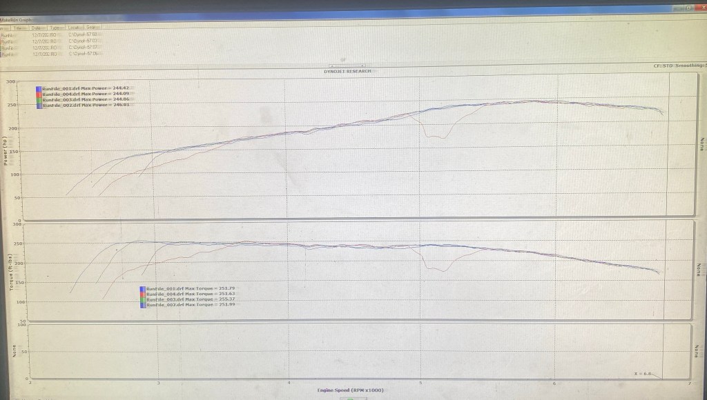
Shockingly, the dyno recorded virtually identical power output in each mode. Even in the green Economy mode, which is supposed to limit boost pressure, the dyno read 244 hp and 251 ft-lbs.
244 hp, 251 ft-lbs
Notice there’s a dip in the chart at one point, the dyno operator said this was likely the ECU pulling timing for a second to deal with heat. The engine was in Eco mode on this pull, but you can see that just a second later the engine picked back up again and posted identical numbers to the other modes.
244 hp is about a 12% drivetrain loss, which is better than I expected. But note that the car was going into winter storage, so I filled the tank with ethanol-free 90 octane, and it may make more power on 93, and even more when the engine loosens up.
What do the engine modes do?
Given that all modes made the same amount of power, the next question is, do the engine modes do anything at all? Knowledgeable people in the N world have stated that the different tunes change the engine’s responsiveness and boost targets in the mid-range, rather than max power. Other sources suggested that the engine modes are only different at partial throttle.
Maybe that’s true, but what about Eco mode? From every account I’ve read, nobody is actually getting better fuel mileage in Eco mode. One source claimed Eco mode only works in the UK. Or that Eco mode is different on different platforms, and limits Velosters to 12-13 psi, but Elantras are limited to 6-7 psi. Well one thing is for certain on my car, either there is no low-boost mode, or all modes are low boost.
Next let’s talk about the tunable exhaust. It did add loudness, but without adding power, I don’t see the point. I like to hear my tires working, it helps me drive at the limit. And so louder pipes just limit my driving.
Finally, there’s the pops and bangs of the burble tune. Internet pundits claim this is to keep the turbo spinning, so that there’s less turbo lag between shifts. I can’t confirm or deny this, as dyno pulls are done in one gear, and so lag (or the lack of lag) doesn’t show up on the dyno. I have a manual transmission, and so I could see this being useful if I missed a shift, but for someone with a 8-speed DCT, I’d question the usefulness of the Rice Krispies soundtrack.
Next year I’ll test the different modes on track and see if I can determine any difference in the data. It may be difficult to ascertain that through the noise of driver error, but we shall see what the Aim Solo data logger says.
At this point, all I can say for sure is that there’s no difference in power or torque in any engine mode or exhaust setting.
There are a lot of racing organizations that have rules which allow cars to have a diffuser, but don’t allow a flat bottom. If you don’t understand how a diffuser works, you might think this is some kind of advantage. If you understand how a diffuser works, you might take a hard pass. So how does a diffuser work?
A diffuser helps air to expand both within the chamber, and in the wake of the car. As a result of this, the air in front of the diffuser drops in pressure and increases in velocity. The result is downforce. Contrary to popular belief, the diffuser itself isn’t where downforce is made; downforce is located where the greatest restriction is, in front of the diffuser.
So, if you have a car without a flat bottom, what’s in front of your diffuser? On the minority of cars, the manufacturer has done a good job making everything smooth, and it can almost replicate a full flat bottom. However, on most cars, and certainly my cars, there’s a shit ton of stuff in the way: transmission, differential, exhaust piping, suspension components, fuel tank, hoses, brackets, exposed frame members, etc. When air hits all of those pieces under the car, it creates local flow separations and drag. Accelerating air through that maze of parts doesn’t create downforce, it creates turbulence.
Diffusers help air expand, accelerating the air in front of it. What’s in front of your diffuser?
Clean airflow makes the most downforce, and thus turbulence is the enemy. Let me give you an example using wings, because I have solid data on that. My Miata has a DIY fastback that provides clean airflow to the rear wing, and it makes 390 lbs of downforce. If I use an OEM hardtop, which has more turbulence around the sides of the canopy, the downforce drops to 300 lbs at the same speed. If I then add AirTab vortex generators and thicken the boundary layer over the roof, the wing makes only 216 lbs. And finally, if I remove the top altogether so that the car is a convertible, the wing makes just 120 lbs of downforce. (These figures come from my testing at Watkins Glen report | data).
So while you can make downforce in turbulent conditions, clean airflow is obviously better, and the situation underneath the car is no different than on top. This is why proper race cars with diffusers have a flat bottom or tunnel under the car, so that they can get clean airflow.
But on a car that must to adhere to rules that don’t allow a flat bottom, the area in front of the diffuser is often a total mess. Moreover, because the diffuser has to begin before the rear axle, any downforce you create is only on the rear tires. Unless your diffuser has a better L/D ratio than your wing, why would you do it?
Maybe that’s a difficult question, let me explain first. On a proper racecar with a flat bottom and diffuser, the throat of the diffuser (where the downforce is located) is often ahead of the rear wheels, around the middle of the car. This means that the downforce is created equally over the front and rear tires. Some diffusers extend even further forward, making more front downforce than rear. Typically front downforce is harder to attain than rear downforce, so this is sort of the holy grail of underbody aero, the way I see it.
Conversely, if your car doesn’t have a flat bottom, and your diffuser begins at the rear axle, you are creating downforce over the rear tires only. A car with a rear wing already creates a lot of downforce over the rear tires, and it does so very efficiently. So unless your diffuser is more efficient than your wing, adding more wing is often a better way to make rear downforce (more wing angle, bigger Gurney flap, more planform area, greater coefficient of lift, etc..).
Nature abhors a vacuum
Let’s play the fantasy game where, without a flat floor, you somehow manage to create a low pressure area in front of the diffuser. Fact: the air everywhere around it is at higher pressure. Because nature abhors a vacuum, the air outside wants to invade the area inside, to balance the pressures as it were.
With great suction comes great responsibility, and so defending that low pressure area becomes your life’s work. There are many ways to seal off the area under the car, such as side skirts (barge boards), or by creating vortices on the sides of the car using canards, or under the car using strakes.
Having done all of that, you also have to attend to what’s happening with your wheels and tires. The most significant problem is that as your tires roll forward, they compress the air underneath them, like a supercharger. This tire squirt sends a high pressure jet of air out both sides of the tire, directly in front of your diffuser! You’ll recall that a diffuser only works because it creates low pressure, and so a jet of high pressure air is a significant problem. It’s less important, but air also intrudes through the spokes of your wheels, and lower caketin covers are required to block this air from going under the diffuser as well.
So as you can see, if you want to make downforce using a diffuser without a flat bottom, the odds are not in your favor. The air under the car is likely turbulent to begin with, and mother nature herself is actively working against you. You have to protect the area of suction as best you can, and if everything goes 100% to plan, you’re still only making downforce over just the rear wheels. When all is said and done, rear downforce is usually gained much more efficiently using a wing.
But I have CFD proof!
But wait, you say, I’ve seen CFD that proves that a diffuser works without a flat bottom!
In the Verus Engineering blog they did a neat CFD study called Is a Flat Underbody Necessary for a Rear Diffuser to Function? The data shows that, compared to a car with a dirty bottom, a diffuser without a flat bottom reduced drag by 26.2 lbs and made 10.2 lbs of downforce. Anytime you can reduce drag and gain downforce, you take it, so this looks like a clear win.
But you could also read their data in a completely different way. Note that the flat bottom alone (without a diffuser) made 23% more downforce than the flat bottom with a diffuser, and only gained 3.5% drag in doing so. So based on this CFD data, one could conclude that this diffuser reduced the effectiveness of a flat floor.
Now that’s a pretty strange conclusion, because I would imagine that any diffuser would help a flat bottom work better. It makes me wonder if the CFD model is too simplistic. Let me not be too critical, because Verus and everyone else publishing CFD is doing us all a favor showing us this data. Computers are simply tools, and with a refinement of those tools, we’ll get better and better data. Let’s just keep moving ahead.
Next, I’ll take a look at Kyle Forsters videos. He has two CFD videos examining flat floors and diffusers, using a NC Miata:
Cut bumper vs Diffuser – Kyle’s first video is just a cut bumper vs diffuser. He didn’t test a flat floor, and the muffler got in the way a bit.
Flat Floor vs Diffuser – In the second video, he uses a flat floor and gets different results.
I watched the videos, and made the following notes. (The downforce and drag values are at 180 kph, or about 112 mph.)
A cut bumper added 6 kg downforce and reduced drag by 1 kg.
A diffuser with the muffler in the way made 4 kg downforce and 4kg more drag. This is not as good as the cut bumper.
Improving the diffuser by removing the muffler added 11 kg downforce, but drag remained the same. Based on this, the cut bumper is still better than the diffuser without a flat bottom.
A flat floor with a cut bumper made 49 kg of downforce and reduced drag by 15 kg.
A flat floor with a diffuser made 50 kg of downforce and reduced drag by 18 kg.
Gleaning this data was a bit difficult, because the comparative data is split across two videos. There are inconsistencies as well; In one video he says the diffuser is 3x more effective at creating downforce than a cut bumper (both with flat floors), and in another video the cut bumper data is virtually the same as the diffuser. So, just like with the previous CFD, there are inconsistencies with the tool, or the operator, or the person interpreting it (mea culpa).
I’ve taken Kyle Forster’s course on aerodynamics, and there’s a lot of CFD on underbody aero, but not much without a flat bottom. However, I’ve had some private consultations with Kyle, and in one of those he showed me a hush-hush diffuser from overseas that was designed to work without a flat bottom. He wouldn’t go into details on the design, and when I asked him how many points that was worth, he shut me down quickly, saying that was private information. But know this, it is possible for a car manufacturer and surely an F1 aerodynamicist to make a diffuser work without a flat bottom. The question is, can you or I modify our cars to do that?
My DIY diffuser
I wanted to know if a diffuser without a flat floor was worth it, so I built one and tested it in the A2 wind tunnel. It’s actually quite neat looking and follows basic aerodynamic principles of vertical and lateral diffusion. With it mounted on the car I was like… damn, that’s cool looking!
Obviously the results in this section apply only to this diffuser on this car, and your results will certainly differ. If you are building your own diffuser, you might take some of my build details and do them differently. (Or better yet, do something else with your time.)
The diffuser is as wide as I could make it between the wheels and extends to the rear axle. It has about 3″ of ground clearance at the front, and the leading edge angles up slightly. My thinking here was to make the area of least restriction (where the downforce is located) within the diffuser itself. I thought this was pretty clever, but this might have been a mistake.
Test fitting my diffuser and setting the height.
I added strakes that diverge from the centerline. These are supposed to spin a vortex off the trailing edge, which should help defeat some tire squirt, by sealing off the center compartment. Thus, the outer chambers of the diffuser are mostly sacrificial in nature, allowing the center tunnel to do most of the work.
The strakes are 3″ off the ground, because at least two of the rulebooks I was looking at state that the minimum ground clearance was 3″. Perhaps the diffuser would have worked better if the strakes were closer to the ground, but rules be rules.
Another detail that didn’t work in its favor is that I made a quick-release diffuser that attached to the car via the trailer hitch and two zip ties. On the upside, I was able to remove the diffuser in one minute. On the downside, there’s a longitudinal cross member behind the muffler that blocks air moving rearward above the diffuser. See the image below.
Quick release splitter mounts to the trailer hitch.
Is this significant? I don’t know. I was mostly concerned with air going under the diffuser, and reckoned anything that snuck between the muffler and top of the diffuser wouldn’t be important. If I had to guess, this probably added some drag, but might have also kicked up some air like a spoiler or big Gurney flap. I’ll have to retest this on my Miata in the future, with topside designed so that air can travel cleanly on top and below.
So how did my DIY diffuser work? If you buy my wind tunnel report you’ll get the full story, but the abridged version is the diffuser made about 15 lbs of rear downforce at a cost of about 3.5 lbs of drag (at 100 mph). That’s not a lot of downforce, but a favorable lift/drag ratio. Except that isn’t the whole truth.
The front of the car lost 14.5 lbs of downforce (when you push down on one end of the car, it goes up on the other), and so the net gain was only .5 lbs of downforce for 3.5 lbs of drag. The data shows that the diffuser would make the car slower. Yuck.
The loss of front downforce is normal, but for whatever reason, the ratio is really bad. I tried 16 different rear aero options in the wind tunnel (5 wings, 3 Gurney flaps, 4 end plates, 2 spoilers) and they all added rear downforce at the expense of front downforce. But all of them did so much more favorably than the diffuser. (In fact one spoiler added both front and rear downforce, but that’s a story for another day.) I don’t know why the diffuser lost an equal amount in front, it’s downright puzzling.
Part of the problem may be the wind tunnel itself. The wheels don’t spin, and the boundary layer grows as air moves along the tunnel. I don’t know if this makes things better or worse for the diffuser, but it’s worth noting.
I’m an amateur aerodynamicist, but I’m well studied, and I have good DIY fabrication skills. I generally feel like I know what I’m doing, but I made a diffuser that made my car slower. But this was my first stab at a diffuser, and I can only improve on this. I also didn’t throw all the tricks at it, and I’m sure that side skirts could have helped.
But even if I could have made the diffuser work better, I’m still only making rear downforce, and losing front downforce in the trade. In my mind, the entire game of budget touring car aerodynamics is getting more front downforce, that’s the real limiting factor in an aero package. From all of this I can conclude one thing, which is that a diffuser without a flat bottom is fuggin useless to me; it’s much easier for me to gain rear downforce by adding more wing angle, a larger Gurney flap, or using a larger wing.
Rules and reasons
Given this, why do the people who write racing rules allow a diffuser, but ban flat bottoms? I can think of three reasons:
Cost control – Rule makers are trying to reduce the cost of a full-scale aerodynamics war. Enh, I guess that’s a concern, but compared to engine mods and tires, aero is the cheapest way to get performance, and a flat bottom is dead simple. I mean, it’s flat.
Give the people what they want – Rule makers don’t want to restrict people from bolting on parts that look cool. This one I sort of understand. If someone likes the look of a diffuser, they should be allowed to use one. Even if it makes the car slower. But what if someone likes the look of a flat bottom? I mean, give the people what they want, right?
Copy/paste – Rule makers are lazy or don’t know any better, so they copy and paste someone else’s rules. We’ve all been there.
Given those reasons, it’s understandable that some racing rules allow a diffuser, but not a flat bottom. Which rule sets are we talking about? I’m sure there are many more, but here’s a quick look:
Grid Life – Street Modified
NASA Time Trials – TT4
Ontario Time Attack – All classes
SCCA Time Trials Nationals – Max classes
But… not all cars are created equal. Some manufacturers have done a great job fairing and flattening the underside, and a diffuser will work well on those cars. Whereas on many cars, a diffuser without a flat bottom is going to be totally useless. For parity across different cars, I feel that any rules that allow diffusers should allow a flat bottom. Full stop.
Next stop… flat bottom
Despite failing miserably in the wind tunnel, I think my diffuser design is pretty good, and so obviously the next thing to test is how the diffuser works with a flat bottom. But this time I’ll test it on a proper racecar, not my Veloster. In the Spring, I’ll trailer Falconet down to A2 and test every combination of underbody aero including flat bottom, diffuser, side skirt, etc. And maybe I’ll acquire some diffusers manufactured by various companies and test those. Finally, I’m really curious about side skirts with no other aero, that should be an interesting one to throw into the mix.
If you value this kind of content, and want to support future aerodynamic tests and articles, please buy me a coffee.
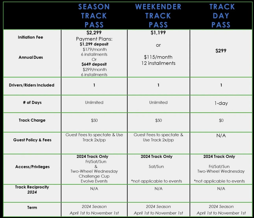
Pineview Run recently released their non-member pricing. Let’s do the math on the various options.
Day Pass
Pineview charges $300 for their day pass, but is it worth it? I think so. I’ve driven or raced 26 tracks so far, and when the asphalt repaving is complete on the track extension, Pineview will rank in my top three favorite tracks. It’s a driver’s track, one that tests your skill rather than how much money you spent on your car. I understand that doesn’t appeal to the majority of people, but for those of us who are students of the game, this is the boss level.
If you’ve driven the track extension already, you know it was very bumpy, and there was a significant dip on the back straight. What happened was, Pineview got shafted by the people doing the asphalt. Core samples around the track showed the thickness was only half of what was contracted for in various locations. That’s being fixed now, and then a final sealer coat will be applied in the spring. And when that’s done, if you’re a driver looking for a driver’s track, a $300 day pass will seem fair.
Look at the thickness going down.
Compared to other track day organizations, the day pass pricing is right in the middle. On the low end you have Mass Tuning, which goes to a lot of tracks for $249 (including Pineview on 7/27-28). And towards the upper end are clubs like SCDA, who charge $439 for every track they visit (including Pineview on 6/29). And so a day pass is right in the middle of what other organizations charge. (I should mention that when you drive with other groups, you won’t have to use a Raceceiver, and you also won’t need to pay for a checkout ride with an instructor to be in a point-by group.)
But if you’re a bargain hunter simply looking for better deals, there are tracks that have $200-250 days. Off the top of my head, there’s Canaan, Nelson, Waterford, and in Canada you have TMP, Great Bend, and I believe Shannonville has some cheaper days. But these are all several hours away and often mid week.
I haven’t seen Track Night in America’s pricing for 2024, but they should also get you on track for under $200. The main drawbacks being you only get three sessions, and the drivers are generally one step below (the Advanced drivers are actually Intermediates, the Intermediate drivers are simply Novices with faster cars). And there’s a lot of driving to get to each track, and driving home at night.
Season Track Pass
The Season Track Pass costs $2300 plus a $50 day use fee. So if you drive the track 12 days, it’s about $280 per visit. That’s a minor discount on the day pass, but if you’re a track rat and come 20 times, it works out to $165 per visit, and it’s difficult to beat that.
The Season Track Pass gets you in on Fridays and you can also attend the motorcycle events for free, and there’s discount pricing on the Challenge Cup. I don’t think many are going for this deal, but in the future people may look back on this and call it a bargain.
Weekender Track Pass
The best deal in motorsports is the Weekender. At $1200 plus a $50 use fee, you’ll beat the day pass pricing after five visits. If you come a dozen times, you’ve now cut the day use price in half, at just $150 per day. Or if you’re a masochist that can manage 24 track days, you’ll do that for just $100 per day.
The caveat is that you don’t get any other events, so if you want to race in the Challenge Cup, you’ll pay the full $2500. Or if you’re a motorcyclist, you’ll pay extra for Two Wheel Wednesdays and the Evolve GT events. You also won’t get any weekdays.
But for those wanting the most weekend track time for the least coin, is there a better deal in motorsports? No.
Once word gets out on how good the long track is, I think you’ll see Pineview transition to a Monticello model; if you’re not a member, you won’t get in. As a member already, it won’t affect me. But the 2024 Weekender pass might be the swan song for public access.
Before this offer expires, I’m looking squarely at my autocross friends who will gladly pay $60 for 6 runs and do work in between. You’ll get more track time in one day at Pineview than you’ll get in an entire season of autocross. If the competition aspect is the most important thing to you, we’ll start a Pineview leaderboard with SCCA classing. It’s this year or maybe never. Fuggin do it.
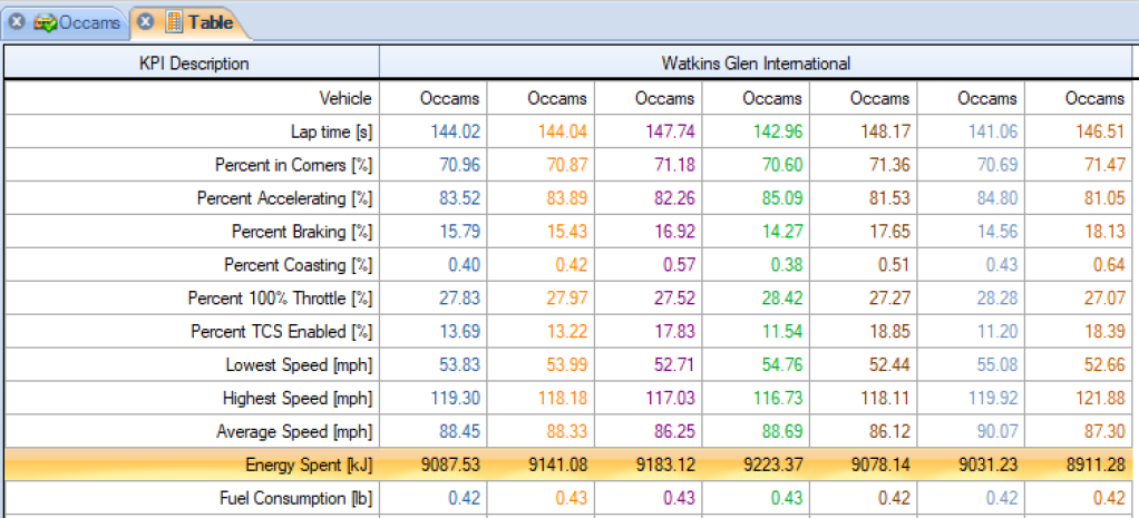
I recently had an opportunity to put three drivers of different experience levels in my Veloster N, and have them drive the same track on the same day. I logged the data on my Aim Solo, and by interpreting that in Race Studio we can see exactly how each driver went about their business.
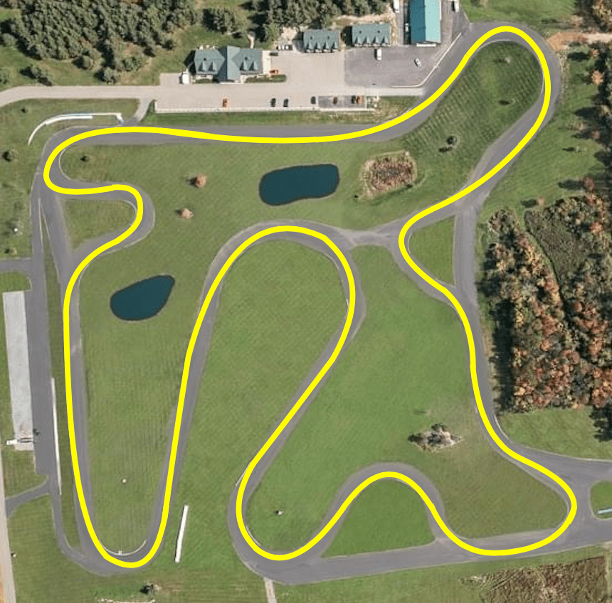
The track is Pineview Run’s short course, and on the driving line, this is just shy of a mile long. Most race tracks are going to be double the size, so keep that in mind when I talk about time deltas.
Pineview Run short course.
The car is my Veloster N, completely stock except for the base model’s roof extension, rather than the Veloster N’s spoiler. I removed the spoiler for scanning purposes, and it wouldn’t change any of the results here. Because it was late in the season, I’d put the my track tires in the basement, and so the car was on Linglong Crosswind all-season tires. I don’t believe this affected anything in the test, but it would be interesting to see the results on a proper track tire. Maybe next year.
The drivers
Let’s meet the drivers:
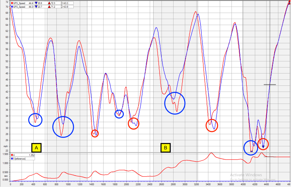
Green – Dan is a novice driver who has done a couple HPDE weekends, as well as a couple Track Night in America events. He’s recently been signed off for solo driving, and after looking at his data and watching him drive, I can confirm he was ready to graduate. His threshold braking is pretty good, and he has acceptable inputs and awareness. Dan also has a Veloster N, and so it was easy for him to get in my car and go quickly. The track, however, is all new to him, and so it took him a few sessions to throw in a hot lap. In the data, Dan has the green lines because, well, he’s green.
Red – Jack is an advanced level driver who races in Champcar. He’s an aggressive driver, and so I’m giving him the red colored lines in the data, to signify the red mist. Well, it’s not really red mist, it’s just a driving style that’s reminiscent of a couple other teammates, Ben and Danny. All three of them break traction early in the corner, and then make multiple fast steering corrections to optimize grip, trajectory, and acceleration out of the corner. This style looks aggressive (and exhausting) on video, because it requires many quick inputs, but it’s actually a very calculated and effective way to go fast. Jack has also never been to this track before, and he’s also never driven a FWD car on track, either.
Blue – I’m the blue lines on the speed trace, because blue signifies cool. Not because I’m a cool cat, but because I drive with a cool head and have a smooth and economical driving style. I admit that the aggressive drivers I’ve mentioned (Ben, Danny, and Jack) are all a bit faster than I am over the course of one lap, but during an endurance race stint, my style is much less abusive on the car, tires, and driver. Because of that, I get into less trouble than anyone I know (3 black flags in 11 years/26 races, and only one was my fault; pat-pat). My big advantage versus the other two drivers here is that I know the track well, because I literally wrote the book on it.
So now we know who the drivers are, we can ask these questions:
How much does driving experience affect lap times? If we compare the Green and Red drivers, we’ll see that the advanced driver goes three seconds faster than the novice. This is mainly down to three factors, which I’ll explore below.
How much does track familiarity affect lap times? For this we’ll compare the Red and Blue drivers, and see that track knowledge (and car familiarity) makes a difference of 1.35 seconds.
Novice vs advanced
The first thing we’ll take a look at is how a novice (green) and advanced (red) driver approach a track that’s completely new to them. I’ve put three callouts on speed trace.
Novice = Green; Red = Advanced
A – Novice drivers are taught to brake in a straight line, and so the speed trace shows straight lines on deceleration. As drivers progress in skill, they learn to release the brakes while they turn in. This is called trailbraking, and results in a speed trace that has a “hockey stick” shape. You can see this at point A. Trailbraking picks up a small amount of time in the braking zone, but more importantly, it allows the car to be pointed down track earlier, so the driver can get on the gas earlier.
B – Another trait of advanced drivers is that they “back up the corner.” This means that braking and turning are done earlier, which allows them to get on the gas earlier. On the speed trace, I’ve drawn green and red vertical arrows that show the point where the driver has committed to full throttle. In most corners, you’ll notice that the advanced driver is to the left of the novice driver (backed up). The best example of this is at the 2200′ mark, where the advanced driver is at full throttle 100′ earlier than the novice driver; that’s over 7 car lengths earlier! The result of this is that the advanced driver gains 6/10ths of a second before the next braking zone.
C – Another telltale sign of an advanced driver is a higher minimum speed, or vMin. I’ve drawn two horizontal arrows here, and in this spot the advanced driver is going 5.5 mph faster than the novice driver, at the slowest point in the corner. If you think about it, this is really an 11 mph difference, because the novice driver slows down 5.5 mph more, and then has to accelerate 5.5 mph more just to get back to where the advanced driver started. Novice students are taught to throw away corner speed for the sake of safety (“in slow, out fast”), but advanced drivers know to keep their minimum speed as high as possible.
Finally, it’s worth noting that the advanced driver not only had never driven a FWD car on track, but he only drove one 15-minute session. On the other hand, the novice driver owns the same car and did four sessions. This shows just how much skill and experience level matter. But before we move on, let me point out this novice driver is better than most novices, given the amount of track time he has. Put a first-time track driver in the car, and my novice is going to put six seconds between them, easily.
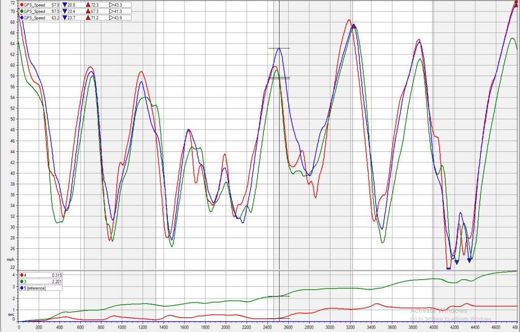
Advanced knowledge vs advanced
Next let’s take a look at how two advanced drivers go at it. As mentioned earlier, Jack (red) is probably a little faster than I am, but I have car knowledge (my car), and track knowledge (my country club).
There isn’t really that much difference between us. I have a slight advantage going into Turn 2, and hold that while we trade corners back and forth. Going into and out of the Turn 11 (2500′-3000′) is where I gain all my time. With a couple more sessions to figure out that corner, Jack would be a couple tenths off me. Take a look:
Youth and skill (red) vs old age and treachery (blue)
A – I’ve put a color-coded circle around each corner indicating which driver had the higher vMin. I have five to Jack’s four, but two of my corners are considerably higher.
B- Jack brakes too early, too deep, and gets on the gas 50′ later than I do. He loses about a second going into and out of The Knuckle. There’s more difference between us in this one corner than the rest of the track combined.
It’s really just that one corner that makes a difference, and it reminds me of another person who is faster than me everywhere but Pineview: my identical twin, Ian. You might know him from You Suck at Racing (blog | book). One reason he’s the fastest on the team is he’s always the fastest through the corner that matters the most. What we’re seeing here is the exact opposite, which is that if you blow an important corner, you blew the lap.
There is one other wrinkle here, which is that Jack was in the passenger seat on my run, but he did his runs without a passenger. Jack is about my size and build (5’11”, 180cm), and I would have gone a bit faster without 180 lbs of ballast. But I’m just grasping at straws here, and with more track time, Jack would eventually surpass me.
Conclusions
In the end, there’s a difference of over four seconds between the three of us, and this on a track that’s only a mile long. On most tracks, it’s safe to say the delta might be 8-9 seconds. Of all the mods you can do to your car, driver mod is the most important mod. And as you can see from the data, you bring that with you, to unfamiliar cars, and to tracks you’ve never driven.
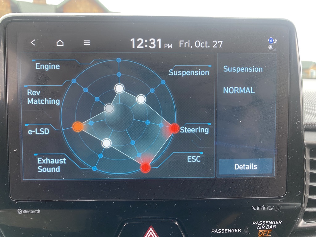
The Veloster N has five driving modes: Economy, Normal, Sport, N, and N Custom. Er… I think I have this right, I don’t know, because I only use two.
Eco – Economy mode limits boost pressure, but from what I’ve read online, it’s not any more economical. So I don’t use this.
Normal – I use Normal mode on the street.
Sport – I’ve never tried this, I don’t see the point.
N – I don’t use this, the suspension is too hard, and the pops and bangs of a burble tune annoy this shit out of me.
N Custom – I use this mode on track. I have the eLSD and steering on full, but pretty much everything else is turned off or on the lowest setting. No rev matching, soft suspension, no stability control, and the exhaust as quiet as it’ll go. For some unknown reason, I’ve also had the engine in the lowest setting all year, which should be a nice surprise when I select full power next year (actually, I later found out there’s no difference in peak output).
My N Custom settings.
I’ve driven my VN on track in both wet and dry conditions, and on good and bad tires. Now that I’ve had a chance to look at some comparative track data, I can answer some questions, such as:
Which driving mode is fastest on a wet track?
Which driving mode is fastest on a dry track?
How do all-season tires compare to a proper track tire?
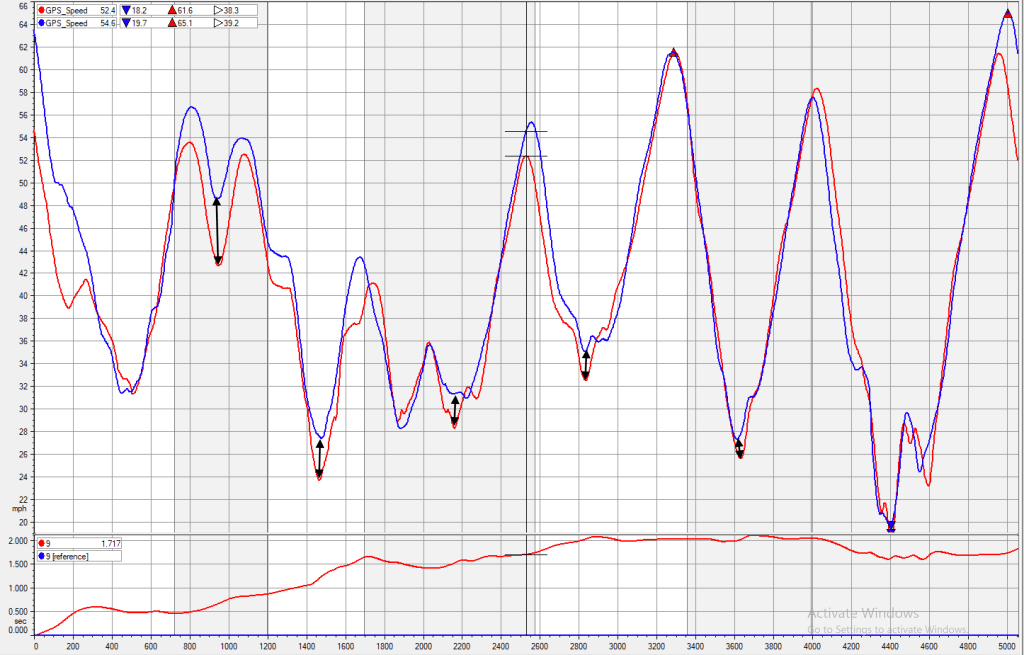
Dry track: Normal vs N Custom
Since I only use the Normal and N Custom modes, I wanted to see how they compared on a dry track. My N Custom mode was 1.9 seconds faster. Woof.
Subjectively, the Normal mode sucks ass on the track. It takes the fun out of driving. The stability control is probably the main culprit, and switching to the N mode (on the fly) resulted in instant smiles from me and a “whoa” from my passenger. The way the car behaves is night and day different in N Custom mode. It’s astonishing.
This immediately changed the way I drove, from trying to maintain a higher vMin, to backing up the corner. I don’t mean to throw jargon at you, so let’s take a look at the data and I’ll explain those terms. I’ve highlighted the the three most significant differences with letters.
Red is Normal mode, Blue is N Custom (nannies off).
This is Turn 2, a right hand turn onto a short straight. You can see that the Red line has about 2 mph higher minimum speed (vMin), but when I get on the gas, the nannies nerf the acceleration and I only get .31 Gs of acceleration. The Blue line has .5 Gs of acceleration, which results in about a .4 second gain. This is entirely down to the car’s intelligent systems getting in the way of my driving.
This is T9, another right hander, this one cresting a hill. By turning off the nannies I can rotate the car, which allows me to get on the gas 95 feet earlier than in Normal mode. We call this “backing up the corner,” and it means that I’ve done my braking and turning earlier in the corner. This allows me to get to full throttle earlier, and gains half a second.
Notice here how the Blue lines are to the left of the Red lines, again this is backing up the corner, and doing that in the final turn is worth almost three quarters of a second as I cross the finish line.
What’s really interesting about this graphic is that I had no idea I was in Normal mode at first. I was driving with a passenger, chatting, and totally forgot to switch modes. Then suddenly I realized I hadn’t changed the driving mode. The Veloster N allows you to do this on the fly, and so part way through the lap I switched modes.
This allowed me to drive the car in a completely different manner. I could immediately feel the difference in the way the car behaved, and was able to extract a higher level of performance, and go 1.9 seconds faster. But I wasn’t aware of how differently I was driving the car until I looked at the data just now.
Wet track: Normal vs N Custom
I also got to try both modes on a cold, wet day. This was the same track with a slightly different configuration to avoid one of the big puddles. It was raining the entire time, and there was a lot of standing water on the track.
In N Custom mode, I spun the wheels a lot on acceleration, and had to short shift to third in a number of places. My best lap was a 1:28.838. In Normal mode, I managed a 1:28.592, but was still getting some wheel spin cresting a hill. So then I left it in third gear and did a 1:26.994. That’s a difference of 1.84 seconds, which is almost exactly the same difference the two modes had in the dry.
So that’s the ticket to going fast in a torrential downpour, put it in Normal mode and drive a gear taller.
The data below isn’t super exciting, the thing to notice is mostly the difference in vMin (or minimum corner speed). I’ve drawn little black arrows to show what I mean. When the nannies are on, I can maintain a higher speed in the middle of the corner, and this results in a faster speed down the next straight. The acceleration curves are about the same in N Custom and Normal, which I find a little surprising, and so I suspect that it’s the stability control more than the traction control that’s helping in the rain.
Red is N Custom, Blue is Normal mode (nannies on).
All-season vs track tires
I have three sets of wheels and tires: 235/40R18 Kumho V730 on Konig Countergram 18×8.5 +43 (42.3 lbs); Pirelli PZ4 235/40R18 on Motegi MR140 18×8.5 +45, (42.0 lbs) and Linglong Crosswind 235/35R19 all-season tires on 19×8 +55 OEM wheels (55.3 lbs).
The only reason I bought the Crosswind tires was because the OEM tires were worn out, and I was looking for the cheapest possible tire I could mount in the winter, while my summer tires are hibernating in a heated basement. I found the Crosswind tires on sale for $65 at Walmart, and expected absolutely nothing from them.
Just the same, I wanted to see what they would do on track, and I’ve been pleasantly supersized. They don’t suck. Because there’s not a lot of grip, they break away gradually, and slides are easy to control. Once sideways, the tires howl like a banshee, which helps you know how much you’re working the tires. Or overworking.
I’m leaning on these $65 tires so hard, they look like they want to come off the bead!
I haven’t tested the Crosswinds back to back with the V730, but I put down a 1:19.1 on the all-seasons, which is about 2 seconds slower than the Kumhos did on a previous occasion. This is surprising, because you’d expect the 200TW to be a lot faster than 400TW. For example, my 1.6 Miata is about 6 seconds faster on RS4s than it is on all-season tires. This all fits in with previous data I hand that shows that FWD cars lose less performance in low-grip situations (such as rain, dirt, snow, or shitty tires).
Red is Crosswing, Blue is V730. Not the same day, and my wife was in the car on the V730, but only a 1.9 second difference.
All said, I’m having Miata-levels of fun on these $65 tires. Had I known this was possible, I wouldn’t have three sets of wheels. With a better all-season tire, like a Michelin Pilot Sport A/S 4, I think you could do everything from daily commuting to track days on one set of wheels. I know a lot of people feel they need track tires for track driving, I’m just not one of them.
This article was originally spread out over several different pages. I’m not sure what I was thinking at the time, but I’ve reorganized this as a single (rather lengthy) article now.
For the full story on how I performed these tests, see Testing Miata Aerodynamics at Watkins Glen. This article is essentially Part 2 of that one, so I can deep dive on the test results of the various aero options.
Summary data.
While datapoints like pounds of downforce at 100 mph, or horsepower consumed, are things we can wrap our heads around, it’s difficult to translate that into the only thing that matters: lap time. Therefore, in the following sections, I also include lap time simulations using OptimumLap.
Testing Miata tops
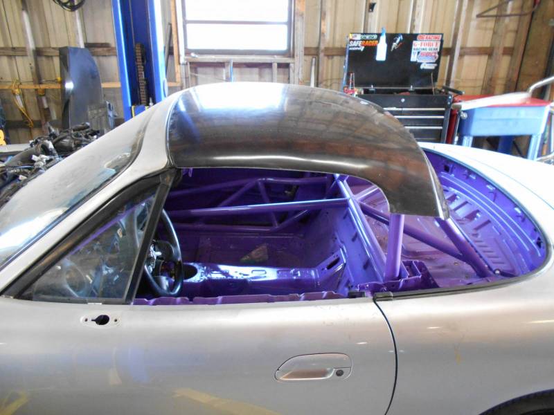
The first thing I wanted to test was the largest knowledge gap, roofline shape. This meant I had to have different options, that would come on and off quickly, using the same brackets. The four options were an open top, an OEM hard top, a Treasure Coast Chop Top (which should approximate a hard top with the window removed), and a fastback of my own design.
I built the fastback before I had the notion to do this test, or I would have built it differently. The main problem is that I made long brackets along the bottom edge, and this required removing the trunk lid. This meant I didn’t get to test any of the other tops with an OEM trunk lid. Instead, I bolted a plywood cover over the trunk cavity. This new trunk lid is about 3.5” taller at the back than a stock trunk. It’s hard to say exactly what the effect of this was, but it’s likely a reduction in drag and lift, akin to adding a spoiler. So when you look at the data later, note that none of the tops used an OEM trunk.
Open top results
Miatas are meant to go topless, let’s start there and address some burning questions:
What happens when you use a wing with an open top?
How much does an open top affect a wing’s performance?
At autocross speeds, is it better to remove the top or leave it on?
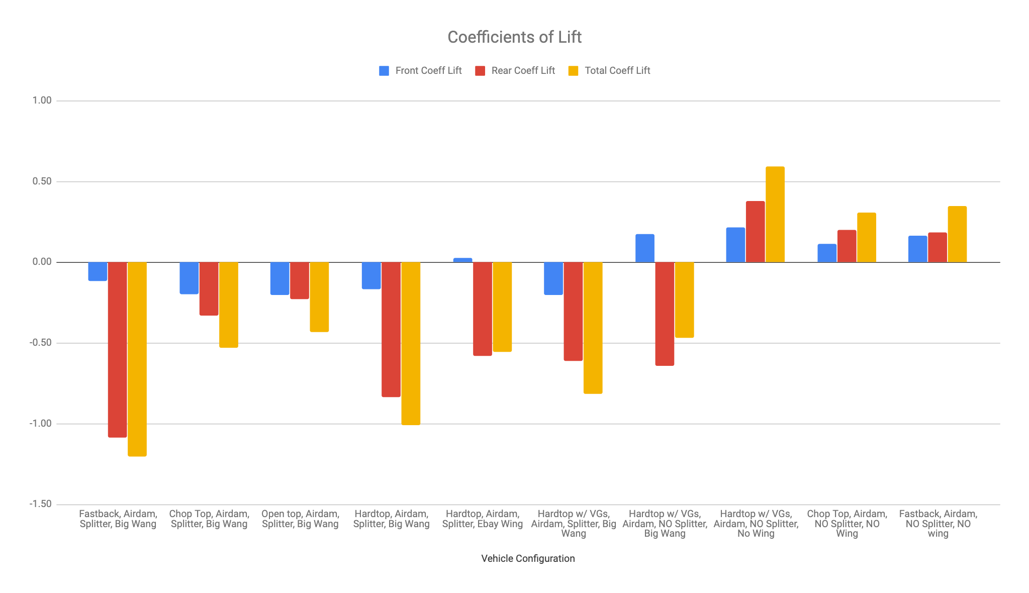
Take a look at the following table, and you can see that an open-top Miata generates about 40% of the downforce as one with an OEM hard top (Total Cl field). Of all the options, this was the worst at creating downforce.
It might be a little confusing that the coefficient of drag (Cd) is better with an open top than with a hard top. This is likely the result of running the tests with the windows open, which turns the hard top cabin into a parachute.
Top
Front Cl
Rear Cl
Total Cl
Cd
L/D %
HP @ 100mph
Open top
-0.20
-0.23
-0.43
0.43
1.01
47.16
Hard top
-0.17
-0.84
-1.01
0.48
2.11
52.78
Let’s plug these numbers into OptimumLap and see what happens. I’ll use three different tracks to represent a range of speeds. These tracks are already in OptimumLap.
Top
Watkins Glen
Waterford Hills
2010 SCCA Nationals
Open top
2:24.02
1:20.97
1:03.88
Hard top
2:22.96
1:19.95
1:03.34
The hard top is worth about one second at both Watkins Glen and Waterford Hills, and just over a half second on the autocross course.
OEM hard top with plywood trunk lid, a concession to the fastback.
For these simulations, the car weight was kept the same. Someone will point out that the top weighs 45 pounds, and that OptimumLap doesn’t factor in the change in center of gravity. Both true. But I can calculate how much weight you’d have to remove from the open top car to match the autocross time of the hard top, and it’s 210 pounds. I’m not sure how high you’d have to place 45 pounds above the car to equal 210 pounds, but it’s probably pretty far up there!
But running an open top car with a wing has two advantages. One, it looks cool. Two, an open top car with this wing beats any top without a wing, every time. That’s kind of jumping ahead in the data, but it’s worth noting.
Let’s get back to the real world and the test at Watkins Glen. Alyssa reported that the car was more difficult to drive with the open top. She had to brake before entering Turn 10, and then had to manage a car that was oversteering badly. With a hard top, she could mash the throttle from the exit of Turn 9 to the exit of Turn 10. That kind of confidence over an 8-9 hour race can mean a lot more than a second per lap.
Chop Top results
Treasure Coast Miata sells their “Chop Top” for budget endurance racing. It’s an economical and lightweight top that does the job of enclosing the roof. This has two benefits: better aero, and you don’t have to wear arm restraints when racing (the car is no longer considered a convertible). I fabricated mounts that attach to the hard top brackets, and with those the total weight of the Chop Top was a scant 7 pounds.
There is a persistent myth in Miatadom, that removing the rear window from a hard top is aerodynamically better. So I put two small Lexan covers on the sides of the Chop Top, closing in the sides. This made the chop very similar to a hard top without a rear window. Let’s add this data to the open top and hard top.
Top
Front cL
Rear cL
Total cL
cD
L/D %
HP @ 100mph
Open top
-0.20
-0.23
-0.43
0.43
1.01
47.16
Chop top
-0.20
-0.33
-0.53
0.45
1.19
49.40
Hard top
-0.17
-0.84
-1.01
0.48
2.11
52.78
As you can see, the chop top allows the wing to work a bit better than an open top, with an increase in downforce. But it’s not as much as you’d think.
However, once you add a wing, the Chop Top performs barely better than an open top. This is interesting, because you’d think airflow over the roof is considerably smoother than an open top. However, it’s what’s happening on the underside of the wing that’s more important, and the Chop Top roof can’t defeat the turbulence coming from the open sides of the cockpit and going beneath the wing.
Chop Top with plywood trunk cover. Note clear lexan and clear gas line, so we can see if the gas is about to overflow.
Next I’ll do the same track simulations, and what I find interesting here is that the Chop Top isn’t really that much different than an open top at any of the tracks. Not enough to really make a difference.
Top
Watkins Glen
Waterford Hills
2010 SCCA Nationals
Open top
2:24.02
1:20.97
1:03.88
Chop top
2:24.04
1:20.82
1:03.79
Hard top
2:22.96
1:19.95
1:03.34
Nevertheless, for those racing with an open top and a wing, the Chop Top is worth a look for a bit of weather protection and not using arm restraints. In addition, we’ve finally dispelled the myth that removing the rear window is more effective. It isn’t. At least when used in conjunction with a wing.
OEM hard top
All along I’ve been citing the data for the OEM hard top without really discussing it. It’s the status quo in racing, looks great, and performs its duty.
In the data, the OEM hard top generated more drag and lift than what I expected from published data. This is likely due to the open windows and wide canopy, which turns the cabin into a parachute. The drag is supposed to be around .38 with closed windows, but we measured over .5. Lift is also supposed to be the high .30-somethings, and we measured .55 (with vortex generators, I don’t have the raw data without).
The hard top with airdam, splitter, and wing made a killer combo: .48 Cd and 1.01 Cl. Those are good numbers. Racing numbers.
Fastback results
The front of my fastback uses the Treasure Coast Chop Top, and the rear fastback section bolts on and slopes back at about 14 degrees. So essentially the roofline is the same as OEM to about the rear window. Starting with the Chop Top made building the fastback fairly easy, and it was also easy to add and remove for this test. (You can see construction photos this and other tops I’ve built at the end of this article.)
An older photo, but the top is the same.
The Chop Top plus fastback weighed 17 pounds less than the stock hard top, and to equalize the two I bolted 8-pound lead weights to the top of the seat belt towers. This was the only time I made adjustments to the weight of the car, and so the open top and Chop Top configurations were a bit lighter.
The fastback significantly reduced drag, and helped the wing create more downforce. Compared to the OEM hardtop, downforce increased 129.7%. Another way of thinking of that is that the fastback turned a 60″ wing into a 78″ wing. Or you could say that the OEM hardtop is so bad that it made a 60” wing behave as a 48” wing….
The large gain in rear downforce was offset by a small loss in front downforce. Essentially, the wing was so effective with the fastback that the front end lifted, changing the height and angle of the splitter, reducing its effectiveness.
Top
Front cL
Rear cL
Total cL
cD
L/D %
HP @ 100mph
Open top
-0.20
-0.23
-0.43
0.43
1.01
47.16
Chop top
-0.20
-0.33
-0.53
0.45
1.19
49.40
Hard top
-0.17
-0.84
-1.01
0.48
2.11
52.78
Fastback
-0.12
-1.09
-1.20
0.41
2.97
44.81
In addition, the fastback reduced drag by 15%. This in itself is pretty surprising, and not only helps top speed, but fuel economy. Combined, the downforce and drag created a lift/drag ratio that was 50% better than the OEM hard top with a wing. Astounding.
Note that the .41 coefficient of drag is actually quite good when you consider that the wing made the most downforce in this configuration, and just as in all of the tests, the windows were open.
But all was not rosy with this setup. Both Anthony and Alyssa commented that the car understeered badly in this configuration, and was boring as shit to drive. Given time, Jeremiah would have changed the mechanical grip by adjusting the front roll couple, by means of spring and/or stabilizer bar. This would have helped balance the vehicle at speed.
Let’s do another simulation in OptimumLap. The fastback gains 1.9 seconds at WGI, and about half that at Waterford, which is pretty spectacular.
Top
Watkins Glen
Waterford Hills
2010 SCCA Nationals
Open top
2:24.02
1:20.97
1:03.88
Chop top
2:24.04
1:20.82
1:03.79
Hard top
2:22.96
1:19.95
1:03.34
Fastback
2:21.06
1:19.02
1:03.12
Vortex generators on an OEM hard top
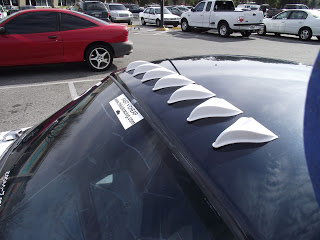
The shape of the Miata’s canopy is abrupt, and if you look at wind tunnel tests, you can see smoke trails that are turbulent, and then separate, as air moves over the top. Vortex generators (VGs) create a thicker turbulent layer of air, which keeps air from separating completely. This should result in less drag, and may also help interaction with a wing.
Most vortex generators you see are cosmetic fakery and don’t create vortices. I bought the real deal from AirTab. Made of thin plastic, they go on with double-sided tape, just peel and stick. The manufacturer says they should be mounted no closer than 4” apart. I set them at 5” on center, and so that made 9 for the roof.
If you do some research on VGs, there’s good data that they work. They’ve been used on semi trucks, RVs, the underside of race car wings, and many places where flow separation can occur. For cars, take a look at the four-part series on Autospeed, where they tested VGs on a Prius and Insight. Even better, check out Hi-kick Racing’s blog on adding VGs to a Miata. VGs decreased his lap time from 1:02.8 to 1:02.1. Here’s a photo from his site.
AirTab vortex generators.
Nevertheless, my expectations were low. If vortex generators are the cat’s meow, then every cat would have them, right? As you can see in the table below, VGs made things worse. Total downforce decreased by about 20%, and drag increased substantially. Take a look at HP consumed at 100 mph and you’ll see you have five less ponies at that speed.
Configuration
Front cL
Rear cL
Total cL
cD
L/D %
HP @ 100mph
Hard top, splitter, wing
-0.17
-0.84
-1.01
0.48
2.11
52.78
VGs, splitter, wing
-0.20
-0.61
-0.82
0.52
1.57
57.58
And this is how those values affect lap time in OptimumLap.
Vortex Generators
Watkins Glen
Waterford Hills
2010 SCCA Nationals
Hard top, splitter, wing
2:22.96
1:19.95
1:03.34
VGs, splitter, wing
2:24.32
1:20.42
1:03.54
We placed the VGs at the trailing edge of the hard top, but it’s possible that moving them forward may have helped some. Or perhaps we used too many? I followed the instructions and they were supposed to work.
The double-sided tape was difficult to remove, and so experimentation with the number and location of VGs wasn’t possible. The only lasting impression the VGs made was the adhesive, it was a bitch to remove and so all further tests would use the OEM hard top and VGs combined.
Miata top conclusions
Different tops change airflow over the roof, and this affects how a wing works. It’s unclear how much of this is is based on turbulence, or because of a change in downwash angle as air hits the wing. It’s likely a combination of both, but we didn’t have time to experiment with wing angle and this mystery remains.
In addition, our data revealed a rolling rake angle that changes ~ ½ degree depending on rear wing configuration, and this impacted front downforce and distribution more than expected. By adjusting chassis rake and splitter angle, it’s likely the total downforce and Lift/Drag efficiency would have been higher, and this may have reduced rolling-rake changes as well.
We can make the following general conclusions about using a wing with different tops.
An open top reduces a wing’s effectiveness by about 2.5x. Or, if you thought you were getting 200 lbs of downforce, you’re getting 80.
A Chop Top performs marginally better than an open top.
The OEM hard top is actually quite good with a wing. But don’t remove the rear window. And don’t use vortex generators.
A fastback allows a wing to perform the best, increasing downforce, while also decreasing drag.
9 Lives Racing Big Wang vs cheap dual wing
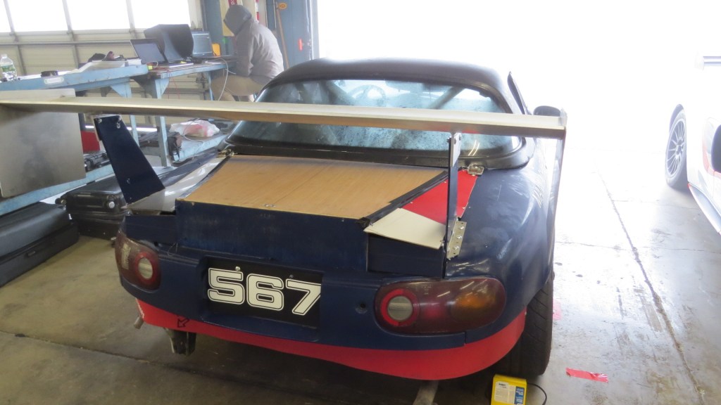
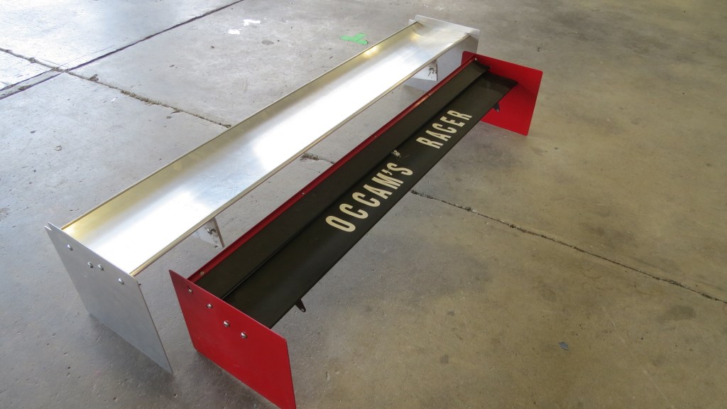
The low price and availability of aerodynamic car wings are making them more common in crap-can endurance racing. You can buy a cheap extruded aluminum wing on eBay, Amazon, or other online retailers for $50, but are they good for anything?
I broke the piggy bank and purchased a 53” double-decker wing for $75, shipped. This wing is sold under a variety of brand names like BestEquip, Mophorn, Neverland, etc, and I’ll refer to this as the eBay wing, because that’s where I got it.
Immediately upon unboxing, I knew I’d have to make some modifications. Like most budget items from China, it came with trunk mounts too low to allow airflow to go under the wing. I trusted the supplied mystery-metal hardware as far as I could throw them, which was directly in the trash.
The main wing felt light, yet surprisingly rigid. The stiffness is partly from the dual horizontal mounting rails, which allow the wing to be mounted at just about any width. However, the exposed slots and flat underside of the wing can’t be great for keeping airflow attached. In the future, I may add some curvature here.
The upper wing felt like a noodle, and I feared it would vibrate and hit the lower wing at speed. So I riveted on a Gurney flap of 1/4” aluminum angle to stiffen it up. I also added a small stop in the middle of the lower wing to limit downward movement of the upper wing.
The end plates had to go, not only because they were too small, but they didn’t allow the upper wing to pivot into the correct position. According to McBeath in Competition Car Aerodynamics, the upper wing should overlap the lower wing at about 4% of the chord (.3” in this case). In order to accelerate the air, the gap must be larger at the front than at the rear. With those two factors set, the slots in the supplied end plates, which support and locate the upper wing, wouldn’t allow us to pivot the upper wing into a useful angle.
Since I couldn’t get the correct spacing and wing angle with the supplied end plates, I made my own from 12”x10” sheet metal, and drilled new upper wing mounting slots. All done I paid a little over $110 for the wing and modifications, and a couple hours figuring all that out.
The car was set up with -1 degree of negative rake, meaning the back was lower than the front. Ideally it should be the other way around, but we got lost debugging what we thought was a clearance issue with a front sensor and didn’t correct the angle.
I set the lower wing angle to 3 degrees, but because of the chassis rake, the main wing was closer to 2.5 degrees. I set the upper wing to 12 degrees. Measured over the entire chord, this created a total camber of about 14 degrees, which is right in the middle of the values that McBeath cites in Competition Car Aerodynamics. Given more time, I would have experimented with the angle of attack of the upper element, as well as the entire wing. However, not knowing how the wing would perform, I chose middle-of-the-road values from a published text, and figured it was more important to avoid a stall condition than maximize downforce. The wing weighed 7.6 pounds altogether, which is very light.
60″ 9 Lives Big Wang vs 53″ eBay double wing.
The wing I used through all the other testing on at WGI is a 60” 9 Lives Racing “Big Wang”. The standard Miata wing is 64″, but my eventual plan was to end-plate mount this, like a Ferrari F40. I never did get around to that, so the wing is a bit smaller than you’d see on most Miatas. (But as you already saw above, the fastback made it behave as a much larger wing.)
When I took the wing out of the package I was immediately impressed by the sturdy construction. When there are only cockroaches left in the world, there will also be 9LR wings. I made my own 12” x 12” end plates and mounting brackets, and had a local shop weld the mounts underneath. The entire setup was about $500, and weighed in at double the double wing, at 14.4 pounds.
I set the wing angle at 5 degrees, but with chassis rake the actual wing angle measured 4.6 degrees. If you look at the 9 Lives CFD open air data, this is right in the middle of the wing’s working range. I knew the downwash angle would change with every top, and that this would change the effective wing angle. But due to intermittent track closures, I didn’t get a chance to sweep the wing angles, and left it where it was.
For both wings I used the same wing stands, which I cut from aluminum plate. Many racing series limit wings to roof height, so I made sure the highest part of the wing was level with the roof. I bolted the base of the wing stands through the sides of the trunk gutter, and while this seemed strong enough, I added another L-bracket on top of the rear fenders, and this stiffened things up considerably.
Wings compared
So let’s see how these wings compared. In this first chart, we’re looking at front and rear downforce using GPS speed alone. It looks like the eBay wing (red) creates more rear downforce as the 9 Lives Racing wing (blue), and when combined with the front, the total downforce is pretty close.
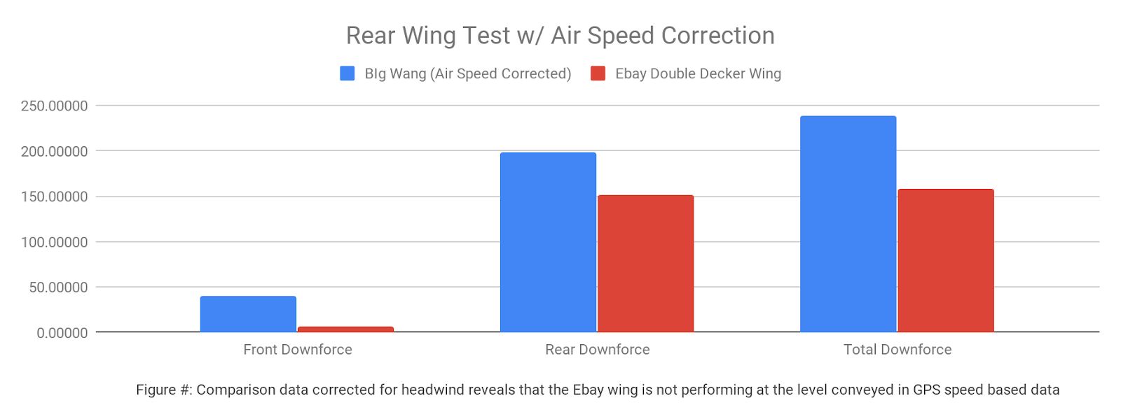
However, the weather had changed during this run, and we had an 11 mph headwind. After correcting the wind speed detected by the pitot tube, a clearer picture developed. See the bar graph below. Here we can see that the eBay wing generated less downforce than the GPS speed would have us believe. This is why you can’t trust testing using GPS speed alone, and why you hire a guy like Jeremiah.
When you add downforce on one end of the car, you can expect to lose downforce on the other end. This is the natural see-saw effect of pushing down on one end. What’s interesting here is that the 9 Lives Racing wing not only made more rear downforce, but it also had more front downforce. How can this be?
The most likely reason is drag. The eBay wing creates more drag, and this rear-biased force lifts the front end. Whatever the case, front downforce, and thus total downforce, is a lot less with the eBay wing.
Take a look at the following table and you can see the corresponding values for coefficient of lift (which we’ve been familiarizing as “downforce”), and drag. We already saw that the 9 Lives Racing wing practically doubled the total downforce, and here you can see it did that while creating 15% less drag. If you look at the final column in the table, you’ll see that the drag reduction alone equals an extra 8 hp at 100 mph.
Wing
Front cL
Rear cL
Total cL
cD
L/D%
Front Load
HP @ 100mph
9LR
-0.17
-0.84
-1.01
0.48
2.11
16.76%
52.78
eBay
0.03
-0.58
-0.56
0.55
0.90
4.43%
60.79
If we divide the total coefficient of lift by the coefficient of drag, you get the L/D ratio, which tells you how efficient the entire aero package is. Here you can see the 9 Lives Racing wing contributes to a setup that is over 230% more efficient at creating downforce.
The data from testing other tops shows that the 9LR wing changes the coefficient of drag by about .03 across all tops, from open top to fastback. By contrast, the double wing changes the Cd by .10. Yowza, that’s a lot.
One final calculation is the front aero load distribution percentage, which gives you an idea of how much the car will understeer (a low percentage) or oversteer (a high percentage). The low values here indicate that with either wing, the car would understeer badly. This is partially due to the negative rake of the chassis and negative splitter angle (both setup mistakes that should have been corrected before testing). However, even with these setup details corrected, the eBay wing would produce a car that understeers more.
As usual, let’s see what happens in OptimumLap. To spice things up, I’ll also add the data from the 9LR wing with an open top.
9LR vs eBay
Watkins Glen
Waterford Hills
2010 SCCA Nationals
Hard top, 9LR
2:22.96
1:19.95
1:03.34
Hard top, eBay
2:25.71
1:20.99
1:03.81
Open top, 9LR
2:24.02
1:20.97
1:03.88
The 9 Lives Big Wang outperforms the cheap eBay wing in every way. In fact, the 9LR wing with an open top out performs the eBay wing with an OEM hard top on any track that isn’t autocross. 9 Lives Racing is a small, made-in-the-USA business with employees who race cars, and you can feel good about supporting them.
But if you’re racing in 24 Hours of Lemons on a $500 budget, you might find that a cheap wing suits your janky crap-can just fine. The wing could have performed better with more fine tuning, but it’s clearly a case of “you get what you pay for.” If you purchase this wing, you might want to take similar steps that I did to limit movement of the upper wing, optimize the convergent gap and wing angles, and get the wing about 6 feet above your roofline. It is Lemons, after all.
Wing vs no wing
For most of the test I used a 60″ 9 Lives Racing wing, but I wanted to see what would happen without it. The coefficient of drag went down by .03 for all configurations. This is rather interesting, because usually when downforce goes up, so does drag. But this wing had the same drag in all configurations.
When I removed the wing, total downforce took a nosedive, and for the first time in the test, the car generated lift instead of downforce. This was an appropriate time to test the hardtops and see how they did without a wing.
First we threw the Chop Top back on and did a run. Then we attached the rear section, making it into a fastback again. And finally we tested the OEM hardtop. Unfortunately the OEM hard top still had the vortex generators attached, so I’ve made an educated guess on the Total Cl and Cd values below (these are in italics in the table below).
Configuration
Front Cl
Rear Cl
Total Cl
Cd
L/D %
HP @ 100mph
Hard top, VGs, no splitter, with wing
0.18
-0.64
-0.47
0.53
0.88
58.75
Hard top, VGs, no splitter, no wing
0.22
0.38
0.59
0.49
-1.20
54.53
Chop top, no splitter, no wing
0.11
0.20
0.31
0.48
-0.64
52.93
Fastback, no splitter, no wing
0.16
0.18
0.35
0.38
-0.80
42.00
OEM hard top, no splitter, no wing
.50
.45
What’s surprising here is that without a wing, the chop top has the best L/D ratio. This is largely because it creates the least lift. Remember that negative lift values are what we’re looking for (downforce), and the chop top’s .31 Cl has the least lift. The fastback creates more lift than the chop top, but it does so with less drag, and in the end, this is makes a faster car.
Unfortunately we didn’t get data for a bare OEM hardtop (without VGs, wing, or splitter), so we don’t know if it’s the shape of the OEM roof, or the VGs that create so much lift. But the total Cl value of 0.59 is quite a bit worse than either the chop top or fastback. Based on the data we obtained doing the wing tests, a bare OEM hard top should have a CD of about .45. It’s hard to imagine the vortex generators adding more than 10% lift, and that would put the total lift around .50.
Let’s see what happens in OptimumLap when we remove the wing.
Wing or no
Watkins Glen
Waterford Hills
2010 SCCA Nationals
VGs, no splitter, 9LR wing
2:25.65
1:21.12
1:03.89
Hard top, VGs, no splitter, no wing
2:29.14
1:23.14
1:04.91
Yikes, that sucks! The wing is worth 3.5 seconds at WGI and even 2 seconds at a short track like Wateford? Amazing.
Now let’s just compare the different tops without wings.
Tops without wings
Watkins Glen
Waterford Hills
2010 SCCA Nationals
Hard top, VGs, no splitter, no wing
2:29.14
1:23.14
1:04.91
Chop top, no splitter, no wing
2:27.74
1:22.85
1:04.63
Fastback, no splitter, no wing
2:26.51
1:22.42
1:04.63
OEM hard top, no splitter, no wing
2:28.17
1:22.87
1:04.80
Here we can see that the fastback is still the fastest configuration, but it’s not a huge difference unless you’re at a high-speed track like WGI. Without a wing, I’d be happy to use a Chop Top at most tracks for the light weight and convenience of strapping in the driver and accessing things like a cool suit, radios, cameras, etc., in the cockpit. And on performance, the Chop Top beats the OEM hardtop, even without factoring in the 38 pound weight difference.
One thing that’s conclusive here is that if the rules allow it, use a wing. This probably even applies to classes like NASA ST6/TT6 that carry a substantial penalty for running a wing.
Airdam and splitter
For most of the test we used a 4″ splitter. This was bolted to a flat undertray, flush with the airdam. I wanted to see what removing the 4″ splitter extension would do. We expected a loss in downforce, but I wasn’t sure if drag would go up or down. You see it both ways online, with CFD data showing that a splitter reduces drag, and the occasional internet expert claiming that drag goes up.
Splitters
Front Cl
Rear Cl
Total Cl
Cd
L/D %
HP @ 100mph
VGs, splitter, wing
-0.20
-0.61
-0.82
0.52
1.57
57.58
VGs, no splitter, wing
0.18
-0.64
-0.47
0.53
0.88
58.75
Score one for the CFD team, the splitter reduced drag slightly. When I removed it, the drag went up from .52. To .53. More importantly, we lost a lot of front-end downforce. Our raw data showed a loss of 69 lbs on the back straight, which calculated to a .38 delta in front coefficient of lift. Let’s see what that’s like in OptimumLap.
Splitters
Watkins Glen
Waterford Hills
2010 SCCA Nationals
VGs, splitter, wing
2:24.32
1:20.42
1:03.54
VGs, no splitter, wing
2:25.65
1:21.12
1:03.89
Obviously, if you’re running just an airdam, and the rules allow it, add the splitter. It’s significant. It’s also worth noting that this was just a plain splitter with no rear curvature or splitter diffusers. Knowing what I know today, the splitter would be twice as effective.
Endurance racing simulations
For endurance racing it’s important to know the amount of energy used per lap, because that determines how far you can go on a tank. You can get this data from OptimumLap simulations. From the energy used, you can determine the length of each driver’s stint, as well as how many laps they can complete in each stint. This can be very important for pit strategy, especially in longer races. Note that simulations are exactly that, and aren’t intended to be exact. But they are useful for making direct comparisons.
The configurations I used for the simulations follow this key. Note that the “B” group has less aero: it uses an airdam, but not a splitter, and no wing.
1a – Open top, wing, airdam, splitter
2a – Chop top, wing, airdam, splitter
2b – Chop Top, no wing, airdam, no splitter
3a – OEM hard top, wing, airdam, splitter
3b – OEM hard top, no wing, airdam, no splitter
4a – Fastback, wing, airdam, splitter
4b – Fastback, no wing, airdam, no splitter
In the table below, the Energy value in the table comes straight from Optimum Lap, and I’ve simply taken a value of 16,500 energy units divided by the energy used to get the number of hours per tank. The Miatas I’ve raced have burned about 7 gallons per hour, so these values aren’t far off.
Config
Cl
Cd
WGI Lap
Energy
Hours per tank
Pit stops
Laps in 8 hours
1a
-0.43
0.43
144.02
9087.53
1.82
4
174.98
2a
-0.53
0.45
144.04
9141.08
1.81
4
174.95
2b
0.31
0.48
147.74
9183.12
1.80
4
170.57
3a
-1.01
0.48
142.96
9223.37
1.79
4
176.27
3b
0.5
0.45
148.17
9078.14
1.82
4
170.07
4a
-1.2
0.41
141.06
9031.23
1.83
4
178.65
4b
0.35
0.38
146.51
8911.28
1.85
3
174.05
Take a look at the first two, this is the open top vs Chop Top, and it’s interesting that they turn almost exactly the same number of laps. The OEM hard top beats those by a lap and change.
But the fastback configuration 4a is the clear winner here, turning 178 laps, two more than the OEM hardtop with the same aero. Make this into a 24 hour race and the fastback wins by seven laps. Notice the Energy column, the fastback with wing is not only turning the fastest laps, but it’s using less gas than any other configuration, save the fastback without the wing.
In the non-aero B-group, the fastback (4b) wins by three laps over its wingless brothers. This is partially because the fastback can take one less pit stop. If I re-run the data with a larger gas tank so that all configurations have the same number of pit stops, then the fastback wins by only two laps.
But once you add a wing, the race is over. In fact the worst combination with a wing (open top) beats the best performing top without a wing (fastback) by a full lap, even though the fastback does one less pit stop.
If you want to check my math, I have a spreadsheet with these values, and for simplicity, I’ve removed a lot of the variables in this table. You have to keep track of things like yellow flags and time taken for each pit stop, which determines the actual driving time per race. The 8-hour race I’ve simulated uses 420 minutes of racing time instead of 480 minutes. Yellow flags at Watkins Glen take longer, and I’ve also subtracted 5 minutes per pit stop.
For shits and grins, the eBay wing again
Let’s see what happens when we use the airdam, splitter, OEM hardtop (without the vortex generators) and the cheap eBay wing. This is configuration 3c in the table below. Look above and compare.
Config
Cl
Cd
WGI Lap
Energy
Hours per tank
Pit stops
Laps in 8 hours
3c
.56
.55
145.71
9393.39
1.76
4
172.95
The eBay wing (3c) loses to every configuration that uses the 9 Lives Racing wing. Yup, even the open top car with a 9LR wing is going to be the hardtop with a cheap wing. However, the eBay wing beats OEM hardtop without a wing (3b) in both a sprint race or an endurance race. So it’s worthwhile running a cheap wing if you have nothing at all.
The biggest difference is the Energy field. Compared to the lowest drag version (4b), the eBay wing uses 5% more gas on every lap. That may or may not be a consequence, depending on how long you’re in the car.
It wouldn’t matter in a sprint race; the eBay wing (3c) would win against the fastback without a wing (4b). But in an endurance race, it would depend on the tank size and driving stint time. If I change the data so that they all take the same number of pit stops, then the eBay wing wins. If I leave the gas tank size as it is, then the fastback without a wing wins.
Wind tunnel testing
I wrote an article called The Dunning-Kruger of Car Aerodynamics, wherein I examine the steps most people go through on their aerodynamic journey. It was lucky that I met Jeremiah online and was able to do these real-world tests, and jump right past the pit of despair.
I’m sort of backsliding on the D-K chart by doing wind tunnel testing now, and who knows, I may slide further backwards towards CFD. But in the future, my ‘Busa swapped fastback Miata, Falconet, will have a full onboard system with strain gauges, pitot tube, and all the works so that I can do the same kind of testing I started with.
Back when I wrote this article, I hadn’t done any wind tunnel testing. Since that time, I’ve tested a Miata in the wind tunnel with the full 9 Lives Racing medium downforce kit, as well as everything in their product catalog. In all, I tested a lot of things:
Splitter diffusers, spill boards, and tire spats.
Canards in various locations and combinations.
Closed windows versus open, plus modifications to reduce drag and turbulence from the open windows, including wickers, mirrors, and venting the rear window in two different locations.
Singular hood vents fender vents.
Brake ducts, NACA ducts.
OEM hardtop with and without a rear window spoiler, versus a CCP fastback.
Blackbird Fabworx spoiler at different angles/heights.
Wings from 9 Lives Racing, Wing Logic, and a couple prototypes.
After payment, you’ll get a link to download the report. It was a lot of work to put together, and so I appreciate the support, it helps this website stay alive, and future testing.
The following article is made up of excepts from my wind tunnel report. You’ll get a more cohesive story, and a lot more data on many more aerodynamic parts, if you buy thereport and read it end to end.
End plates on wings are necessary; they separate the low-pressure region under the wing from the high-pressure area on top of the wing. The suction side of the wing is what does most of the work, so by keeping the high pressure side from bleeding into the suction side, the wing makes more downforce.
The shape of the low-pressure region under the wing is different for every airfoil. However, for most wings designed for motorsports, you’ll find that the low-pressure region is at the front of the wing and often extends ahead of the wing. The low-pressure area extends about a chord’s distance below the wing as well.
The shape of the low-pressure region below the wing depends on the airfoil. I inverted the images so that it relates to car wings. This image is from Race Car Aerodynamics, and I highly suggest you buy the book.
Given that information, and after looking at the preceding image, you might conclude that a good endplate should be shaped to exactly cover the high and low pressure regions of the wing. And from that, you might surmise that a good endplate for a 10” chord motorsports wing should extend 10” below the wing, and should have a lot of surface area concentrated at the front. And that’s how I see it as well. However, some end plates have most of the area towards the rear of the wing, and I can’t say I understand that. But aerodynamics is full of weird contradictions, and perhaps some of those end plates work.
With the amount of companies selling improved end plates with different shapes and sizes, you’d assume there was something to be gained over a plain rectangular end plate. And because some of these fancy end plates cost a couple hundred dollars, and boast CFD-designed pedigrees, they must be doing something useful, right?
CFD and wing efficiency
Some of my wind tunnel data conflicts with published CFD (computational fluid dynamics) data. This isn’t surprising, as CFD is just a computer calculation, and not real-world data. Manufacturers typically test wings in free-stream CFD, meaning that the wing is suspended in mid-air, as only a computer simulation can do. This is the best way to calculate what happens when you change wing angle, add Gurney flaps, or change the shape and size of end plates. Free stream CFD is essential, because it eliminates everything in front of the wing. This is really the only way to compare one thing to another.
But when you put a wing on a car, everything in front of the wing affects its performance. Wind speed and direction, cars in front of you, and open windows can make a huge difference. Plus there’s the shape of your car, the angle of the windshield, aerodynamic devices on your car, like splitter, canards, hood vents, vortex generators, GPS antenna, wing stands, … you name it, every single thing that’s in front of your wing changes how it performs. You’ll never get the same amount of downforce from your wing as the free stream CFD data shows. Not even close.
You can research wings on Airfoil Tools or Bigfoil, or use tools like Javafoil and CFD, and you’ll find wings that have a 14:1 L/D ratio, or better. But when you put the wing on the car and adjust the angle of attack, you’ll be stoked when your wing has half of that.
For this reason, anything you do to improve the efficiency of the wing in free-stream CFD is meaningless until you put it on the car. For example, modifications to wing end plates can reduce drag, and this shows up in CFD as a gain in wing efficiency. But when you put the wing on the car, the drag of the wing is inconsequential to the total vehicle drag. Touring cars are essentially huge rounded bricks, and wings are tiny streamlined objects by comparison, and so you can understand that the drag from the wing is essentially nothing compared to the drag of the vehicle.
In reality, the only thing that matters is the aerodynamic efficiency of the entire vehicle, and you typically get that by going after as much wing downforce as possible. Modifications to the end plate that reduce drag might increase free stream wing efficiency, but they do that by reducing wing downforce. And this makes the L/D ratio of the car worse, and the car goes slower. Ergo, it’s utterly worthless to optimize wing efficiency in free stream CFD by reducing drag. If you use CFD for anything, it should be for optimizing the wing for maximum downforce.
Testing end plates in a wind tunnel
Before I get to the testing data, let me tell you exactly how shit stupid I am. My aerodynamics sensei Kyle Forster had these things to say about end plates:
Use a rectangular shape. Adding vents, cuts, and other tricks are more likely to reduce the performance of the wing than improve it.
Optimizing the performance of the wing end plates is the least important part of the entire vehicle’s aero package.
You might think I would take Kyle at his word. He worked for the Mercedes Formula 1 team as an aerodynamics engineer during the manufacturer’s most dominant years. But I’m also a stubborn, pig-headed ass who believes in getting his own data. So I took three end plates (four if you count that I turned one backwards) to the A2 wind tunnel and spent my hard-earned money to see if he was right.
I tested four wings in the wind tunnel, but when I got around to testing the end plates, they were all swapped onto a 55″ (1397 mm) 9 Lives Racing wing. This is the benchmark motorsports wing for many good reasons, so I figured why not go with the industry standard.
I first tested the basic rectangular end plate, which is made from an aluminum street sign that I simply cut in half, rounded the corners, and called it done.
Sorry about the image quality, these are stills from the video monitors in the wind tunnel.
I then swapped those for a popular CFD-designed end plate. I’ve always found this design to fly in the face of reason – why is there a big cut out right where the low-pressure region is?
CFD end plate with a pressure relief cut on the top, and a large radius cut into the leading edge.
I then turned the end plate backwards and tested that. From my point of view, it seems like the end plate might perform better with more surface area facing forward and less at the rear. It wasn’t a great fit, though.
The CFD end plate didn’t fit very well when I flipped it around backwards. I got two of the holes to match up and called it good enough.
Finally I tested an end plate of my own design. It’s in some ways the opposite of the CFD end plate, having a lot of surface area forward and tapering towards the rear. There’s a very small relief cut on the upper back corner that’s supposed to reduce a vortex there (er… so I’ve read). But more significantly, this end plate has a very small wicker on the trailing edge.
My Occam’s Racer end plate with more area forward and Gurney flap. This is the same end plate in the cover image.
Let’s see how the end plates performed:
End plate
cD
cL
Vehicle L/D
Rectangular
.467
-.382
.82
CFD
.475
-.386
.81
CFD backwards
.474
-.385
.81
Occam’s Racer
.480
-.398
.83
Coefficients of drag and lift with various end plates. cL is a negative number because it’s showing downforce; more negative is more better.
Wind tunnel data
So let’s unpack the coefficient data and translate that into more common figures, like pounds of downforce and horsepower consumed.
Rectangular – Vehicle L/D ratio .82
Baseline to compare with other end plates
CFD – Vehicle L/D ratio .81
+1.8 lbs total downforce
4.1 lbs drag = 0.4:1 L/D ratio for end plate
+1.1 hp used from drag
CFD backwards – Vehicle L/D ratio .81
+1.5 lbs total downforce
3.5 lbs drag = 0.4:1 L/D ratio for end plate
+.9 hp used from drag
Occam’s Racer – Vehicle L/D ratio .83
+8.8 lbs total downforce
6.9 lbs drag = 1.3:1 L/D ratio for end plate
+1.8 hp used from drag
The first thing you’ll notice is that the CFD end plate increased downforce by almost 2 lbs at 100 mph. That’s more than the rectangular end plate, but not much. As a consequence of that additional downforce, there’s a bit more drag.
Turning the CFD end plate backwards resulted in less downforce, but also less drag. Overall, the CFD end plate performed the same forwards as backwards. Surprising.
Another surprise was that my Occam’s Racer end plates gained 8.8 lbs of downforce over the rectangular plate. Not surprising, this also resulted in more drag. However, these end plates resulted in the best vehicle L/D ratio.
Racing simulations
Those numbers are all very close, and you might be wondering how they affect the only thing that matters: lap times!
To find out, I put the coefficient of lift and drag values into OptimumLap and ran them around two race tracks, the autocross course from 2010 SCCA Solo Nationals, and Lime Rock Park. I typically use these two tracks because they are close in lap time, but are completely different with respect to speed. I’ve also included my local track Watkins Glen, because it’s very high speed and should spread the results out more. (My wind tunnel report shows lap time comparisons for every part that I test, as well as some useful combinations.)
End plate
cD
cL
Autocross
Lime Rock
WGI
Rectangular
.467
.382
61.79
61.03
134.74
CFD
.475
.386
61.79
61.05
134.81
CFD backwards
.474
.385
61.79
61.05
134.81
Occam’s Racer
.480
.398
61.78
61.04
134.81
Lap times
On the autocross track, my end plates won by a whopping .01 seconds. At Lime Rock, the rectangular street signs won by the same insignificant margin. At Watkins Glen, the “No Skateboarding” sign went .07 seconds faster than either of the fancy end plates.
Discussion
The CFD-designed end plates were a disappointment, and put an exclamation point on my rant at the beginning of this post about using free stream CFD. Look, I’m not at all doubting that these end plates worked better in CFD and returned exactly what they calculated. But overall performance didn’t change facing either way, and shows how useless free stream CFD can be in the real world.
The custom end plates I designed are based on a hunch that I should put most of the area low and forward. More significantly, these end plates have a small Gurney flap on the outer edge, and it’s likely that the shape of the end plate was no better than the others, and it was simply the addition of the wicker that gave this end plate the most downforce. Most downforce doesn’t mean best, as it wasn’t terribly efficient and only returned a 1.3:1 L/D ratio above and beyond the rectangular plate. Using these end plates would make the car faster on a tight track, but slower on most race tracks.
In the end, there really is nothing wrong with a rectangular end plate. If you don’t have the means of CFD testing your entire vehicle and optimizing the end plates to your entire car, then a rectangular end plate is your best bet. I make mine from street signs that I buy from my local metal recycler for $1 per pound. And so both end plates are less than $2 and come with amusing graphics. It astonishes me that people will pay much more for something that performs worse.
But let’s face it, no matter what you do to the end plate, it’s not going to make it significantly worse, either. End plates with cuts and vents are a great place for personalization, they are a source of many silly conversations, and they throw competitors off the scent. In the end, I say do whatever you want, it won’t matter much anyway.
But if you want to hedge your bets and do the least work, just stick to a rectangular end plate. Learning this lesson cost me $300 plus a lot of time and effort, and it proves I should just have just believed Kyle Forster.
But it wasn’t a total waste of time and money if that keeps other people from making the same mistake. So if this article saves you money, please consider buying me a coffee, or if you want 50+ pages of the same kind of data, then buy my wind tunnel report. It’s only through contributions that I can afford to do wind tunnel testing and continue the lord’s work. Thanks!
Postscript
After posting this article, I got a bunch of great comments on the Professional Awesome Technical Forum on Facebook. This group has a wealth of knowledge that surpasses my own, so please see this post, scroll through the comments, and benefit from the global knowledge base.
Canards, also sometimes called dive planes or dive plates, are little winglets on the front bumper fascia. They are mysterious pieces of aero, because the shape, size, curvature, and mounting locations are all over the map. There’s no standardization at all. What they do depends on a combination of factors, and also who you ask.
I really like the explanation of dive planes on the Verus Engineering site: “Dive planes, also referred to as canards, allow you to shift the aero balance forward, possibly aiding you and your setup in balancing out a large rear wing or diffuser. Dive planes also help seal the sides of the car and help evacuate air from the wheel well, further reducing lift and drag in some cases.”
I love how much conjecture is in that description, and if you read between the lines, you’ll see that they might not help your car at all. I would sum it up like this: “Sometimes canards will make your car faster.”
The reason canards might make your car slower is because they are at the leading edge of the car, so they affect everything behind them. Airflow down the sides of the car, underbody, wake, and especially the rear wing could all be negatively affected.
Size matters?
Canards don’t have an airfoil shape, and so they create downforce through pressure, rather than suction. In Race Car Aerodynamics, Katz examines dive plates, and gives them a Cl of .03 and Cd of .01. That 3:1 lift/drag ratio is like a spoiler rather than a wing, which makes total sense all things considered.
You might use canards under the following circumstances.
If you have an older car that has the front tires exposed to airflow (Miata, etc), then canards can help deflect air away from the tires.
If you have a car with a flat bottom, canards may help seal the sides of the car via a vortex, which may help the underbody creates more downforce.
If you have a splitter and aren’t using spats or other tricks to extract air sideways, then canards can be beneficial when placed low on the bumper fascia. I’m going to dig into this one in more detail.
DIY canards
The Velsoter N bodywork has a lot of vents, swoops, and hard angles, so there aren’t a lot of options on the size of the canards, their shape, or where to mount them. Effectively, the bodywork itself dictates the dimension and locations of the canards.
The vents and bumper fascia elements make it difficult to mount canards. There were only three logical places to put them.
I made my canards out of aluminum street signs, which I get at the local recycler for cheap. I shaped them to fit the bumper fascia and curved them so they would fit where they would. All of the canards are identical in shape and curvature.
The top canard mounts just below the headlight. The headlight has a flat spot below and in front of it, and by putting a canard below that, I essentially increased the amount of planform area for free. (More area means more area for high pressure to form.)
Upper canard alone fits below the headlight and utilizes the extra planform area of the bodywork.
I placed another canard 5” lower than the top canard. It sits on top of the air curtain duct on each side of the car, so there’s no way to mount it any lower. I’ve several aero companies put their canards in this general location, so I figured it should work there.
Double canards.The canards are duct taped on, because that works fine for wind tunnel testing.
I also placed one canard down on the bumper fascia as far as it would go. This was an audible call made by AJ Hartman during the wind tunnel test. I hadn’t planned to put a canard there, but I’m glad I did, the results were astounding. This is why you bring a professional with you to the wind tunnel!
Middle canard moved to the bottom position.
Test data
Recall that all of the canards are identical in size and shape, and so the primary thing I was testing was the location of the canards: top, middle, and bottom. It’s important to note that the car has a splitter and a wing, because canards will interact with both.
In the table below, front downforce is listed as a positive value, while rear downforce is negative. This is the normal see-saw effect of pushing down on one side of the car, the other goes up. But also, there may be some loss of rear wing downforce via turbulence from the canards. The Total downforce is obviously the two added together, and this is important when we look at Lbs of drag.
The next columns are drag, and if you divide the total downforce by the drag lbs, you get the L/D ratio, or how efficient the canard is. The top canard is the most efficient at 3.91:1. Finally the last column is HP, which is how much power is consumed by the canards at 100 mph.
Downforce @ 100 mph
Drag
Front
Rear
Total
Lbs
L/D
HP
No canards
0.01
0.05
-0.04
-0.04
0.89
0.04
Top only
15.18
-2.17
13.11
3.35
3.91
0.95
Mid only
11.13
-1.91
9.21
3.30
2.80
0.88
Top and mid
26.30
-4.08
22.32
6.64
3.36
1.82
Bottom only
85.61
-17.76
67.95
28.98
2.34
7.78
Top and bottom
100.79
-19.94
81.06
32.33
2.51
8.73
The top canard was the most efficient, probably because it’s mounted below the headlight where the extra planform area effectively adds to the canard’s surface area.
The middle canard has exactly the same drag as the top canard, but because it didn’t have the extra bodywork area to work with, it made less total downforce. The 2.8:1 L/D ratio is quite close to what Katz cites. When I look at canards from various manufacturers, they usually put them in about this location, but you can see it’s the least effective of all.
Using both the top and middle canard together was simply additive. Meaning, the data doesn’t show any effect of the canards working together to create more downforce than either one did individually. It makes me wonder why canards are usually mounted in pairs.
Take a look at that bottom canard, it made over 700% more downforce than the canard that was just 8″ above it. Drag also went up by a lot, but that’s an acceptable tradeoff for this much downforce.
Finally, I added the top and bottom canards together to combine the better L/D ratio of the top canard with the high downforce from the bottom. This gives just over 100 lbs of front downforce, and when matched with more rear downforce, would provide a lot more grip.
Discussion
I didn’t expect much out of canards, and I’ve often slagged them off as poseur junk. I was wrong about that. If AJ hadn’t prodded me to try the canard in the bottom position, I’d have missed some very useful information.
Canards aren’t an airfoil shape, and don’t create suction underneath like a wing does. The top surface is theoretically limited in the amount of downforce it can create via pressure to less than cL 1.0. But since the surface area of the canard and the angle of attack was identical in each position, then the canard itself can’t be making more downforce.
Suction is really the only way to explain a gain of this magnitude, and it’s not the canard that’s doing the heavy lifting, it’s the splitter. The canard must be extracting air from the wheel wells, and/or from the sides of the splitter, which is creating more suction under the splitter.
As a consequence of that, the bottom canard also makes so much more drag. Drag is a normal byproduct of downforce, but the canards in either of the other locations were much more efficient than the bottom.
One possible explanation is that when placed this low, the canard creates a much stronger vortex. Vortices take a lot of energy to spin up, and a bigger vortex makes more drag. Or perhaps it’s simply that canards are an inefficient way to create downforce, and drag increases at a higher rate than downforce? In any case, the location is obviously a very important factor in canard placement, and I’ve only played with one variable at this point, height.
Sometimes you see a canard with end plates, or a vertical outer edge. That kind of thing might help a canard create more local downforce, because it should hold more pressure on top of the blade. But this may not be ideal for the lowest canard, as the whole point of that one is to spin a vortex off the outer edge and suck air out from below the car. Or it might work better. Further testing is required.
It’s worth noting that you shouldn’t apply these downforce numbers directly to your car, unless you have a Veloster N with the same splitter and wing. If I’ve learned anything from this test, it’s that canards are finicky. About the only thing you can conclude from this test data is that height matters. And that’s only one variable that’s been isolated, with angle of attack, size, shape, fore-aft location, and wicker edge yet to be determined.
Pre-production test model
Before I sign off on this one, I’d like to go back to my statement that “Sometimes canards will make your car faster.” AJ recently stated in the Professional Awesome Technical Forum that canards have improved the L/D ratio of every car he’s tested in the wind tunnel. Well this is because he’s a professional aerodynamicist! He knows where to place canards, and what angle to run them at. The average aero enthusiasts buying appearance-grade canards and placing them where they look cool is a performance crap shoot. Good luck with that.
If you enjoyed reading this article, check out my wind tunnel report. It’s over 50 pages of similar data, but goes over many more pieces of aero, and to a much greater depth.
It’s been quiet on the Occam’s Racer site for a couple months. Most of that is the aftermath of knee surgery. Meds, physical therapy, lack of sleep, and persistent pain, have kept me away from my computer entirely. On top of that I tore my rotator cuff (downhill mountain bike injury, just before knee surgery), and I am going under the knife again in December. This has also compounded my inability to sleep, which makes writing or doing anything quite difficult.
Boo hoo, so what else is going on? Falconet.
The Hayabusa is a Japanese falcon, and many people know that name from the legendary motorcycle that was inspired by it. The smallest bird of prey is called a falconet, and that seemed like an apt moniker for a Miata with a Hayabusa motor. That’s right, I’m not getting out of Miatas after all, I’m putting a motorcycle engine in my race car and going after track records.
Mike Smith of Spec13, who is the engineer responsible for Hayabusa swapped Miatas (and soon for other cars), is the guilty party here. I was completely ready to sell everything Miata related and live the easy life with my Veloster. But after being a passenger in his test mule (1600 lb Miata with Busa swap), and doing a little napkin math, I’m back in.
The Hayabusa engine and transmission are about 200 lbs total, and this should get my race car below 1900 lbs. More importantly, there’s a lot of empty space in the engine compartment, which will allow me to do some unique things with front aero.
I’m fairly confident that Falconet will make more front downforce than any Miata in existence, and that means I can also add a shit ton of rear wing. Downforce in a lighter car means more grip, because grip gains are relative to the weight of the car.
Let me explain. Let’s say you have a modern track car (BMW, Camaro, Mustang) that weighs 4000 lbs with the driver, and you add 400 lbs of downforce. This will get you nearly 10% more grip, because grip goes up fairly linearly with weight (not exactly, though, see How Downforce Affects Tires). Now add the same amount of downforce to a car that weighs 2000 lbs, and you get almost 20% more grip. Lightweight cars benefit more from aero than heavy cars, and that’s where Falconet will shine.
It won’t be the fastest car at horsepower tracks, but at places like Lime Rock and Nelson Ledges, where there are long, high-speed corners, I expect Falconet to swoop in on some lap records. And on low speed tracks, where it’s difficult for big V8s to get all the power down, I imagine Falconet can prey on heavier cars as well.
Personally, I think I can do a record lap at Pineview, but probably not any other track. Not only do I know Pineview very well, but I’ve kind of lost my nerve on big tracks. But Mike Smith is a very fast Spec Miata driver, and Occam’s Racer teammate Alyssa Merrill has uncanny speed herself, and being all of 120 lbs, she’s probably the one who will break hearts and records.
Alyssa’s job also includes adding BMW-sourced antilock brakes, an onboard telemetry system, and general chassis setup. I’ve driven her car, she knows what she’s doing far better than I do. She also has mad skills in 3D design and will be making custom aero pieces like canards, wings, and vortex generators (kidding!).
Mike’s job is, of course, building a Busa engine and fitting it to the car. But not just any engine, it’ll be a stroker. He’ll also install paddle shifters, reverse gear, a taller drive ratio, and anything else required in the drivetrain.
My job is providing the car and doing all the aero. The top will be my fastback version 2, which is a single piece that connects from the front windshield frame to the trunk. The previous version of my fastback reduced drag by 20% and added 30% more rear downforce. Some of this can be attributed to improved backlight angle, but even more might be the width at the B pillars.
The extra width of the factory hardtop, or any street-based hardtop that has to seal the side windows, is wider than the windshield frame. Therefore, air gets shoved into the cabin, and causes downstream turbulence and drag. This effect is compounded when the car is cornering. Unfortunately every fastback I’ve reviewed, from 3D printed to curvaceous fiberglass, has the same problem at the B pillar, and will never perform as well as mine.
Fastback v2 sitting on my street car. Notice the width at the B pillars. Every other hardtop has to cover those huge gaps on the side.
One of the things I discovered in my wind tunnel test was how to reduce the effect of open windows, and I expect fastback v2 to be even better, as it has some new tricks to further reduce drag and turbulence. First is a reduced window opening at the top edge, which is where most of the turbulence is. I also added a drip edge here, but the purpose is really to keep air from curling inside. Finally, the B pillar is well rounded for smooth extraction.
Fastback v2 has smaller window openings, a drip edge, and rounded B pillars.
I don’t know exactly what the front end will look like yet, but I’m taking a lot of inspiration from the Fittipaldi EF7, with it’s front wing molded into the front bumper, and the extractor hood.
EF7 front end is giving me a lot of ideas.
This wouldn’t be possible on a normal Miata, because the engine and radiator take up too much space. But look at the Busa engine and how much room there is in front for an extractor radiator and some kind of wing arrangement below that.
With the Busa engine in place, the amount 0f free space in the engine compartment means an extractor hood is easy, and also room for radical front aero.
You’ll notice how far back the engine sits, and this, coupled with the lack of engine weight, means the car will have more weight on the rear wheels than the front. I’m not sure how this will affect the handling, and this might require non-standard spring rates. There will be a lot of experimentation, but that’s not a problem because we have unlimited testing days at Pineview Run.
But don’t expect rapid progress on this project from my side, I’ll be in a sling for 6 weeks come December, and won’t be able to life more than 5 lbs until next summer. But I have a couple partners in this project, and they can make a lot of progress while I’m on the mend.
So that’s what’s going on over here, big plans to smash some lap records. Falconet FTW.