| If you’d like your car featured in Readers’ Rides, see the information on this page and then let’s get the ball rolling! |
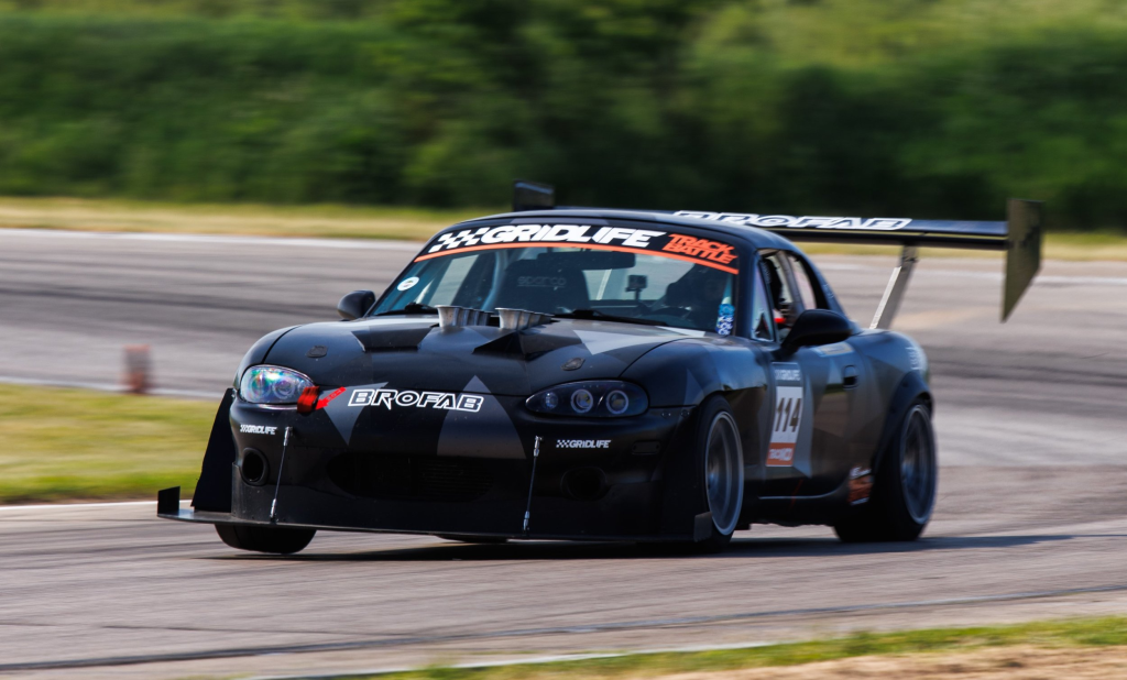
The first Readers’ Rides feature is Dylan Pudiak’s 1991 Miata. I’ve watched his car transform from average, to exceptional, back to average, and then to its current status as the northstar build for all normally aspirated BP engines. What began as an engine failure turned into a journey of epic proportions. It didn’t happen over night.
A Hero’s Journey
If you don’t know what the Hero’s Journey is, it’s a template for storytelling where a person goes on an adventure, is victorious, and comes home transformed, with knowledge to bestow upon others. Think of stories like Star Wars or The Hobbit. Dylan’s journey follows this template closely, so I thought I’d tell his story like this:
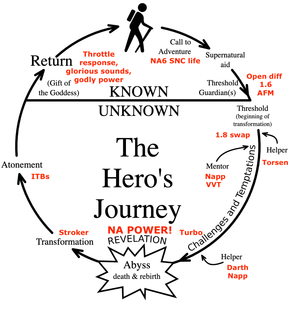
The Call to Adventure
Our story begins with a Call to Adventure. For Dylan and many other driving enthusiasts, that call was autocross. But on his way home from dodging cones, our hero encountered Supernatural aid in the form of bad luck. Or as many early Miata owners know it, SNC Life.

When the Miata was released in 1989, the engine had a short-nosed crank (SNC) that could eventually wobble or shear the crank keyway. Half way through 1991, Mazda released long-nose crank engines to fix this problem. Fortunately for us, Dylan had the earlier 1991 Miata, and while driving home from his call to adventure, the crank bolt ejected itself.
The common solution to this problem is to find a later 1.6 engine with a long-nose crank and replace the whole mill. But that would be the end of the story, and a pretty boring one at that. Instead, Dylan recognized that the Threshold Guardians to a faster autocross time were the lack of power from just 1597cc and an open diff with a fragile ring gear. Luckily, these things can be easily remedied with parts from later 1.8 Miatas.
The threshold: from known to unknown
A significant part of the Hero’s Journey is the journey into the unknown, and for Dylan, this begins with swapping in a 1.8 (BP05, 1994-1997). Most people would have chosen a later model VVT engine, but a standard 1.8 was the easy button, because he could keep the 1.6 AFM and ECU, and do an exhintake cam swap as well.
The exhintake cam swap is where you take an exhaust cam, grind off one end, install it on the intake side, and re-time it. The exhaust cam doesn’t have any more lift than the intake cam, but it has more duration. When properly tuned, this can add up to 8 hp, which puts the engine close to what a VVT makes.
For simplicity, Dylan kept the ECU from the 1.6, as well as the air-fuel meter (AFM). The AFM is a flapper type valve that doesn’t flow enough for anything more than a stock motor. People with modified 1.6s often use a RX7 AFM, which instantly gives more power on the top end.

I don’t believe I’ve seen anyone swap in a 1.8 engine and keep the 16 AFM; most people splice the wiring to run a 1.8 ECU and much less restrictive MAF sensor, or better yet, go to a standalone ECU. The path less chosen probably cost Dylan a few ponies, and with this combination the car put out 102 hp and 100 ft-lbs on a Land and Sea dyno. These dynos read lower than Dynojets and after correcting by 112%, that’s something like 114 hp at the wheels. This is respectable, but if he’d done all of that with a Megasquirt, he’d be looking at something in the mid 120s.

To put the power to the ground more evenly, Dylan had to address the other Threshold Guardian, the open diff and 6″ ring gear that can break on stock power. He found a 7″ ring gear and Torsen LSD locally from Stefan Napp, which brings us to the other important character in this story.
Han Solo, Gandalf, and Goldilocks
In Dylan’s Hero’s Journey, Stefan Napp plays several important roles, and is simultaneously Helper and Mentor. He’s like Gandalf, Obi-Wan Kenobi, Samwise Gamgee and Han Solo all wrapped into one. Later, he’s also Darth Vader and a drug-pedaling pimp, but that’s getting ahead of the story.
With Stefan’s guidance, Dylan swapped his 1.6/1.8 mongrel, to a junkyard VVT, and then threw the Napp-recipe at it:
- VVT sourced from a junkyard
- Head work, ported and shaved 0.040″
- Custom bumper routed intake, Skunk2 intake manifold
- Raceland header, custom 2.5” exhaust
- Megasquirt 3
- 150 whp, 127 ft/lbs on 93 octane, as measured on a Land and Sea dyno
All of those modifications resulted in 150 whp on Rick Gifford’s “heartbreaker” Land and Sea dyno. On a Dynojet, that’s probably in the neighborhood of 165 whp. It’s worth pausing a moment to mention Rick, because he’s a Gandalf-level engine tuner with a dyno at his house. He serves as another Mentor character in pretty much all the Dylan and Stefan stories. (Rick also tuned by 1.6 Miata).
So let’s call it around 165 (Dynojet) horsepowers at the wheels. Sounds perfect doesn’t it?

In fact it was perfect. I drove Dylan’s car at Pineview Run, and it was the Goldilocks of Miata motors: not too much power, not too little, just right. The power felt ideal for the chassis, retaining all of the characteristics of a momentum car, yet providing instant tractable power, and enough oomph to occasionally surprise.
I still don’t know that there’s a more satisfying combination of engine and chassis, it was magical. Stefan’s K24 Miata was there the same day, and I honesty liked Dylan’s more. That’s really saying something.
On a personal note, driving Dylan’s car at Pineview was also the moment I realized I was a complete dumbass. At the time I was being an iconoclast by trying to tune a 1.6 engine, and I thought cams and bolt ons could help my B6-ZE run with BPs. Three corners into driving Dylan’s car I understood exactly what a huge mistake I’d made.
From Goldilocks to Jenna Jameson
Speed is a drug. Napp is a dealer. Dylan saw the huge gains Stefan made, and was naturally tempted to take a bigger hit. Too much is never enough.
So the next stage in Dylan’s journey was to take Goldilocks and hook her on smack, then turn her out onto the street as a common hooker. OK, maybe that’s a little harsh, it’s just a turbo we’re talking about; but it sucks and blows just the same.
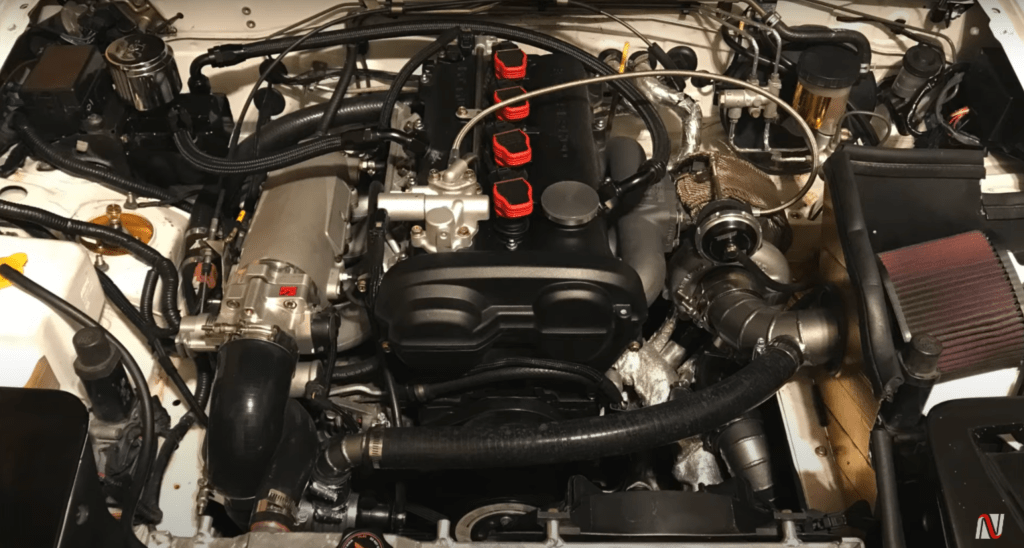
Modifications at this stage included the following:
- Garret gt2560r turbo
- Flyin miata exhaust manifold
- Ported turbo exhaust housing
- Flyin miata oil cooler
- ATI Fluid damper
- R8 Ignition Coil Kit
- 252 whp, 221ft/lbs @14psi (same dyno)
I don’t pay too much attention to turbo Miatas, but it seems like ones putting out mid 200s at the wheels are a dime a fucking dozen. After all the work they’d done to get Goldilocks to dance like a ballerina on swan lake, it seems terribly underwhelming to wind up with a common skank twirling on a brass pole.
I didn’t get a chance to drive Dylans turbo at Pineview, but it wouldn’t surprise me if it was slower on that track. But I did get to drive Dylan’s car on the street on the way back from Watkins Glen, and I will say the acceleration was exhilarating. So fucking what.
Transformation and atonement
The next stage in the Hero’s Journey is the revelation that brings our protagonist out of the abyss, transforms him, and sets him on the path to atonement.
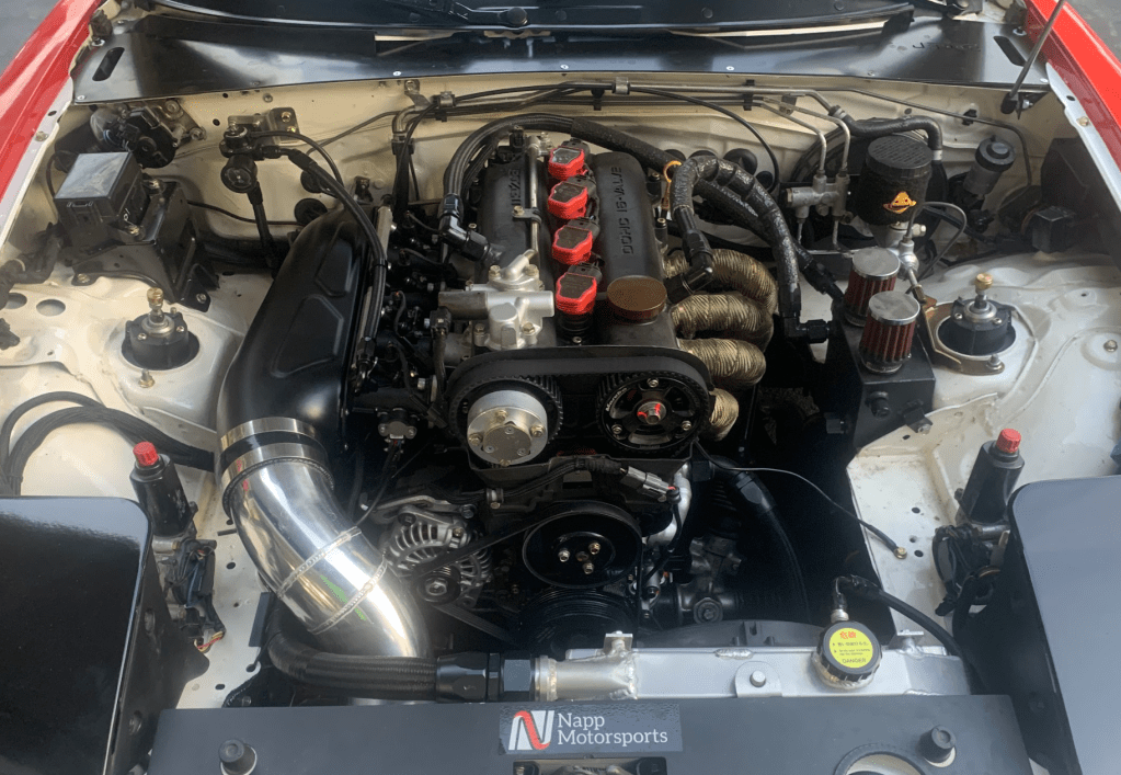
What set that off was typical turbo problems: heat. With rose-tinted beer goggles, Dylan looked back on the simplicity, reliability, and ease of driving that Goldilocks NA. And thus the revelation to go back to normally aspirated power. And then go completely overboard, boring the engine to the maximum displacement. And then add cams, shim-under bucket lifters, and ITBs. It has, well, everything:
- 85.5mm Supertech pistons 11:1 (2L displacement)
- Manley H Beam rods with ARP main and rod bolts
- ACL Race main and rod bearings
- Boundary oil pump
- +1mm intake and exhaust valves
- Supertech dual valve springs with titanium retainers
- Tomei 252 10.8mm Intake Cam, Tomei 256 10.0mm Exhaust Cam
- Shim under bucket lifters
- Maruha adjustable exhaust cam gear
- 0.040” head shave, 0.030” cometic head gasket, final compression 12.25:1
- Full head porting
- 3.6kg flywheel
- Fluidamper
- Jenvey ITB’s and SPS plenum
- Custom halfrad setup
- Break-in tune without plenum: 184 whp @ 7400 rpm, 132 ft/lbs @ 6300 rpm
- Estimated 200 whp @ 8000 rpm on E85
The end result still needs final tuning, but it’s likely 200 whp on a Land and Sea (heartbreaker) dyno, and well over 200 on a Dynojet. This is about as far as you can go with a Mazda BP engine, and I want to personally thank Dylan and Stefan for reaching the limit.
Suspension, wheels, brakes
You don’t do all of that work and roll around on OE anything. Dylan did it right yet again:
- Ohlins road and track coilovers, corner balanced
- Custom extended top hats
- Racing Beat front and rear swaybars
- Paco strong arm fender braces
- 4.1 Torsen diff
- V8 roadster hubs
- Full polybushing kit
- Frame rails
- 1.8 brakes
- Hawk HP+ panda
- 15×9 Konig Countergrams
- RS4s 225/45

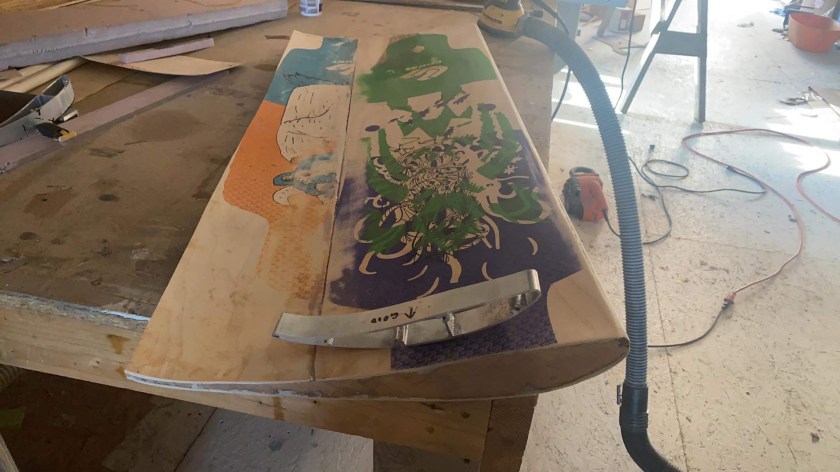
Aero
I’m an aero guy, so let’s take a look at how the air moves over and around the car. Starting at the front, Dylan has a SPS air dam, AG Limited front lip and custom undertray. The top is a standard Miata hardtop, but has a spoiler extension on the roofline. For rear aero, Dylan has two trunks, one with an Ikon Style duckbill spoiler, and another with a APR GTC200 wing.

Judged against modern aero like a 9 Lives Racing medium aero kit, Dylan’s aero isn’t quite up to snuff, and probably has a little more drag and little less downforce. But I honestly wouldn’t change a thing! This is 1990s perfection. Visually, this is the pinnacle of Radwood-era aero, and “fixing” this would be as sacrilegious as fixing Jennifer Connelly’s overbite. For a dual duty car that sees more street than track, changing the aero would be pointless.

It’s amazing to look back at this Hero’s Journey and appreciate the Gift of the Goddess. Thank you Dylan Pudiak and thank you Stefan Napp, for showing us the way.