In the world of car aerodynamics, it’s rare to get drag reduction and downforce at the same time. Usually there’s a trade off, where a certain part adds downforce, and with that you get more drag.
Hood vents are one of those magic items that often benefit both drag and downforce; it’s a double win. And because hood vents also aid in engine cooling, that makes them a triple win. Every race car that is allowed to have hood vents should have them. Period.
But what kind of hood vent? There are many products available online, from Gutentight, Race Louvers, Singular, Spiked Performance, Trackspec, and many others. And then there are the DIY options such as stamped steel floor vents from a home improvement store, or 3D printing huge time attack style vents, or simply cutting a gaping hole in the hood. What’s best?
Luckily someone has done a lot of that testing, and provides the data for free. Al Watson of Race Louvers has 27 PDFs on his site, detailing wind tunnel runs on many different cars. I encourage everyone to read those, but I also want to do a deep dive on Miata hood vents in particular, since I race one, and compare his data with my own. Let’s get into it.
Commercial Vents
When it comes to Miata hood vents, the shape of the hood dictates the shape of the vent to some degree. First, because there’s a bump in the middle of the hood that’s difficult to work around, and second, because there are support structures underneath.
Take a look at the following picture of Gutentight louvers installed on a NB hood, and you can see the reason the vents are shaped the way they are; to preserve the support ribs under the hood.

RGR is another company making similar louvers with the same strategy: keep the support ribs. This makes for easier installation, because there’s just a single layer of sheet aluminum to cut through, but it sacrifices some of the venting area.

Is it important to preserve those support ribs? Kinda. The hood is aluminum, and if you delete all of the supports underneath, the skin is too floppy on its own. So keeping some of the ribs makes sense, but you certainly don’t need all of them.
Spiked Performance hood vents require cutting out one of the support ribs on each side. This makes for a larger vent, and is still structurally sound. However, Spiked doesn’t include a vent in the middle of the hood directly behind the radiator. If you’ve read the PDFs on the Race Louvers site, you know that venting directly behind the radiator is the most important area to vent!

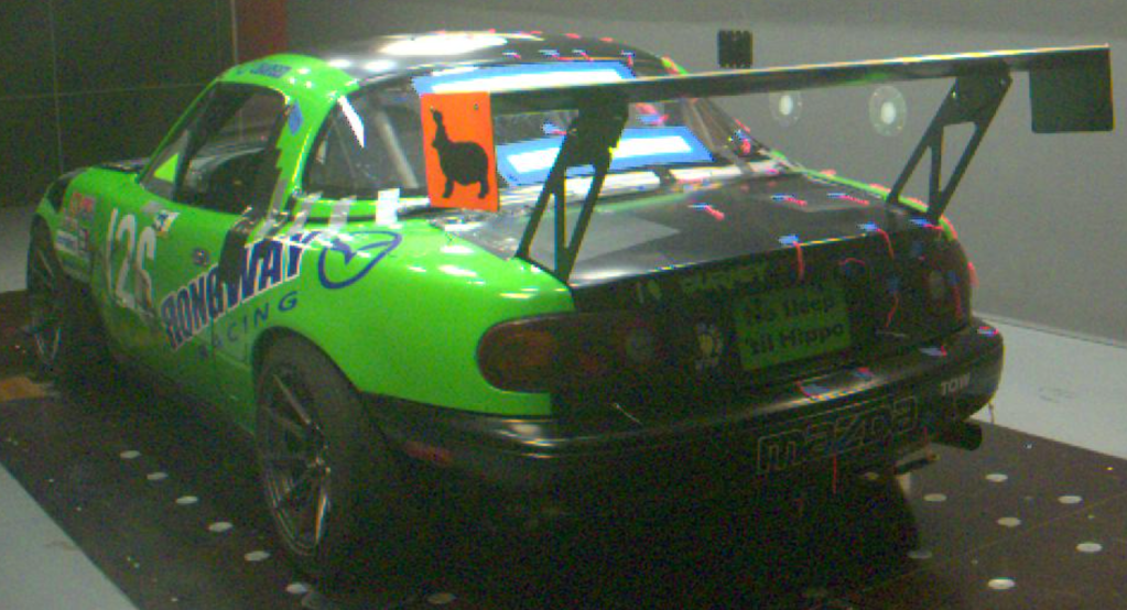
Which brings me to Singular, who makes a three-piece louver that’s like the Spiked vents on the sides, but also includes a center vent . It’s a smart design that I tested in a wind tunnel. They worked well, and you can read about that in my wind tunnel report.

If you’re going to keep most of the support structure underneath, that about wraps up the options for Miata hood vents. However, there are some hood vents that aren’t constrained by the OE hood supports, and designed to put as much venting as possible directly behind the radiator. This will provide the optimum performance, but you pay for that twice: more money and a more difficult installation.
Among this variety of hood vents you have products from Trackspec and Race Louvers. For $330, the Trackspec louvers are priced well, but I haven’t seen them in person, so I don’t know how far above and below the surface the louvers extend, and that’s a very important variable.
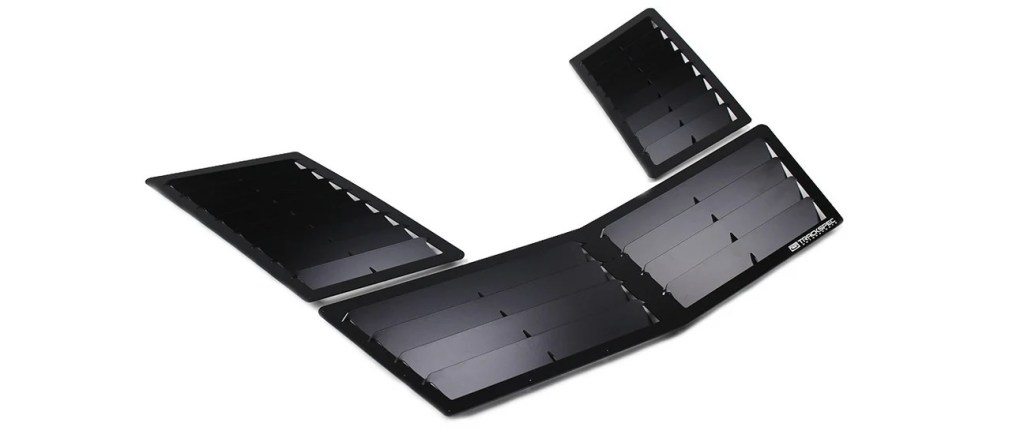
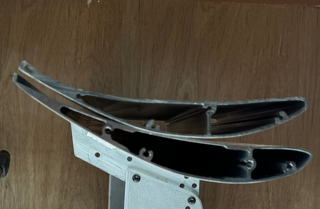
If you dig into the Race Louvers reports, you can see that the height of the louver is important, and that more is height is better. However, the distance the louver extends below the hood is equally important, and many manufacturers ignore that aspect entirely. So until I get my hands on some Trackspec louvers and measure them, I’ll have to reserve final judgment.
Race Louvers
Which brings me to Race Louvers, and the two types of vents they offer for NA/NB Miatas. The first is a double vent called the XL. Compared to other side vents, these are quite large and universal, meaning not specifically designed for a Miata.

Race Louvers also sells a center vent that can be paired with two smaller side vents. You end up cutting out the center hood bump, and a lot of the support structures underneath.

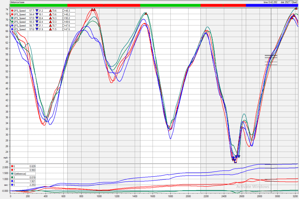
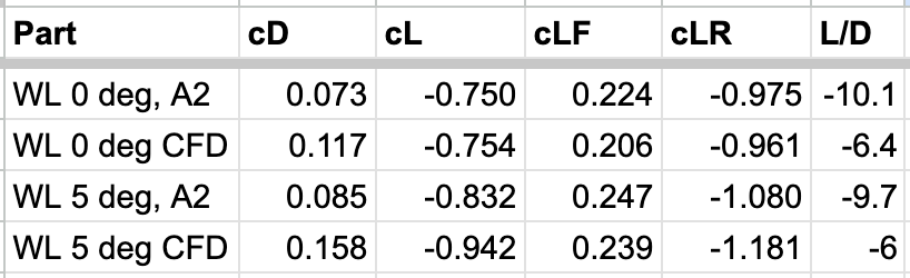
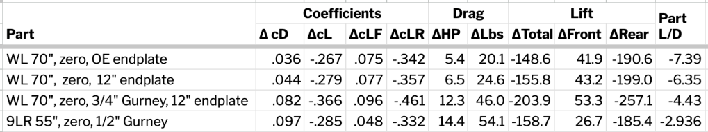
So how do the vents compare? If you look at the data from Race Louvers, you can see that the triple vent out performed the double vent, with more downforce and less drag. However in radiator pressure differential (which we can interpret as cooling benefit), the XL side vents were slightly better (data not shown here).
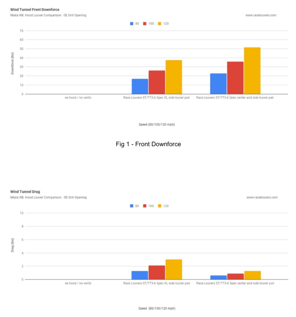
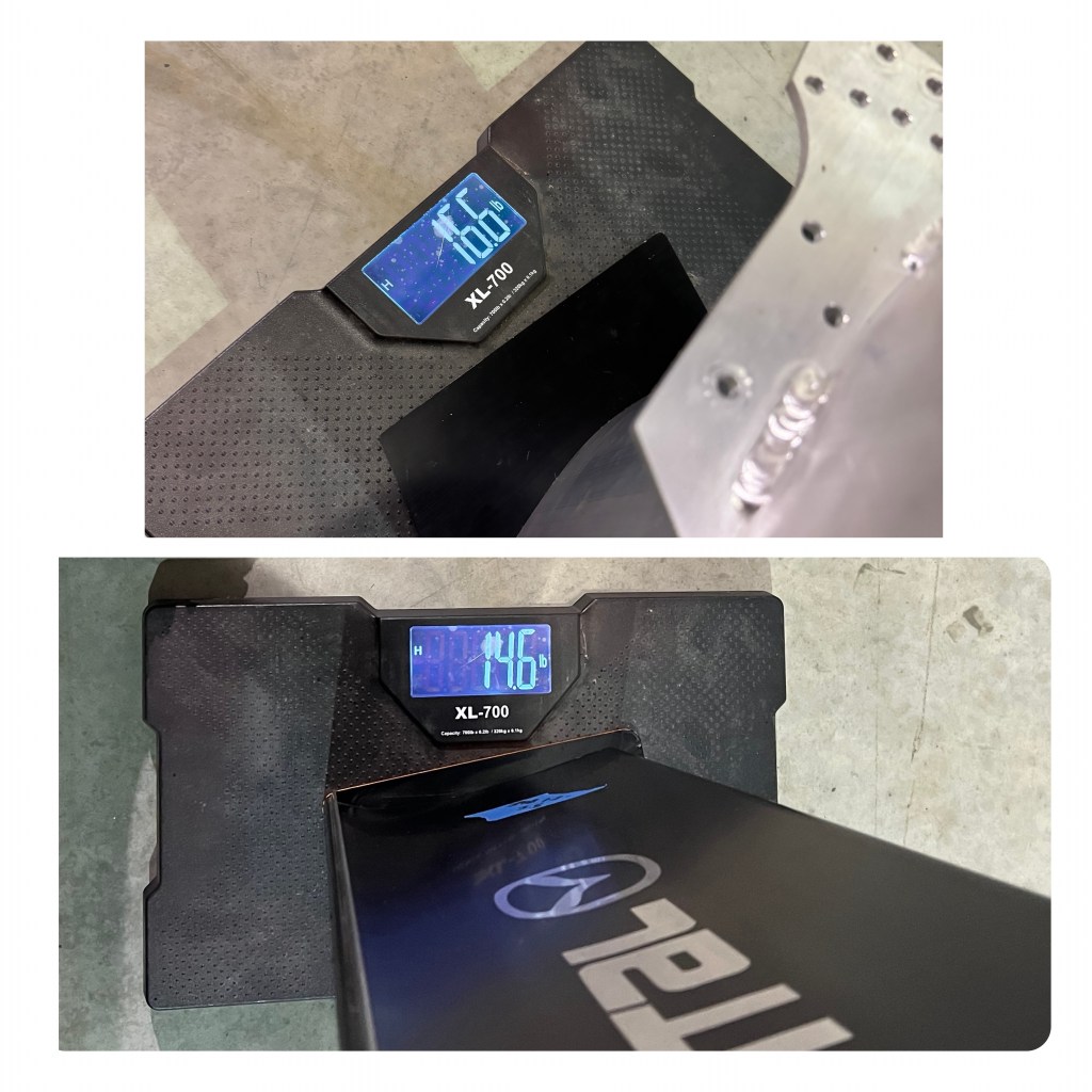
Let’s ignore cooling for now and just look at the performance numbers. The double vents made about 25 lbs of downforce at 100 mph, and added two pounds of drag. The triple vents had 35 pounds of downforce the same speed, and only one pound of drag.
Why the difference? Probably it’s the efficiency of the center vent. The most important place to extract air is directly behind the radiator, and side vents just aren’t as effective as a center vent.
Note that more downforce is possible using the taller RX louvers. The louvers Al tested on this Miata were NASA ST/TT 4-6 legal and only 3/8” tall; if your car is unbound by silly racing rules or in NASA ST/TT3 and faster, you can use the full-height RX louvers and gain more downforce.
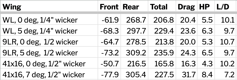
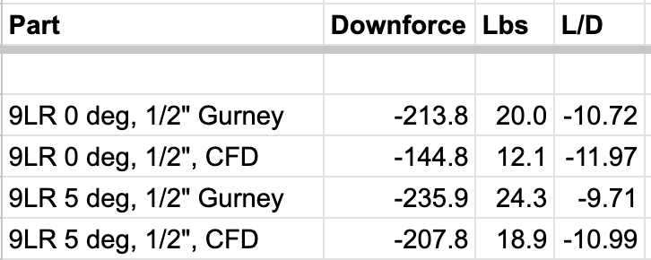
So how did the Singular triple vents compare to the Race Louvers triple vents? They made almost half the downforce, at 16.5 lbs, and reduced drag by 3 lbs over Race Louvers. That drag reduction is worth about .6 hp, and not a bad tradeoff. Whether you want double the downforce or half a horsepower is up to you, but I would personally take the downforce.
But these were two different Miatas on two different days, and so there may be some minor differences associated with that. Both cars had the same 9 Lives Racing front aero, and I’d guess the variability between the cars isn’t worth a re-test.
DIY Solutions
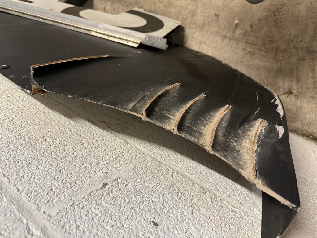
If you’re more concerned with price than performance, or need to work your hood vents around a custom motor swap, then you may want to design your own. One thing I learned from the JKF Aero course was that you don’t absolutely need louvers, you can make a big gaping hole in the hood, and it actually works quite well. The main problem is a loss in rear downforce from turbulent air exiting the duct, but that can be an acceptable trade for more front downforce.
Hood vents in general have been shown to reduce rear downforce, but it’s less than a 5 lbs at 100mph. It’s unclear how much of that is due to the leverage effect versus dirty air hitting the wing, but in either case, the loss in rear downforce is usually so negligible that you can ignore it.
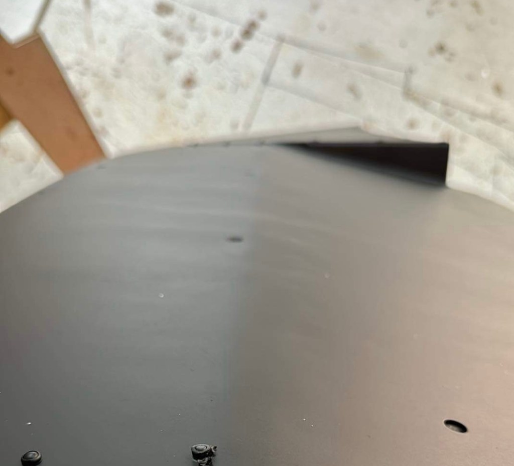
My Miata has a Hayabusa swap from Spec13, and the engine sits quite tall at the rear of the engine bay, but leaves the front completely open. For an application like this, a fully ducted extractor hood makes more sense than hood vents. Although I will still need vents on the side of the hood to make sure the engine bay itself is cooled, from the heat dumping off the headers.
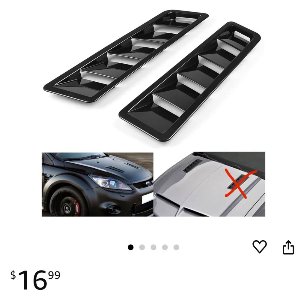
For side vents, the obvious solution is Race Louvers, but the cheapskate in me isn’t ruling out 3D printing, Amazon shit, or just using a can opener on the hood.
Best practices
The number one piece of advice I can give you is to buy Race Louvers hood vents, they have been designed to outperform every other hood vent on the market, and the data is clear in this respect. For the cheap bastards who DIY their own aero (ahem, my people), here are some guidelines.
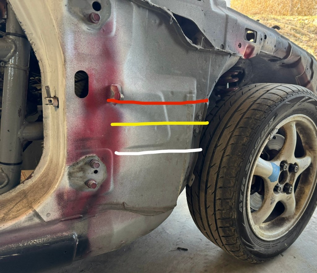
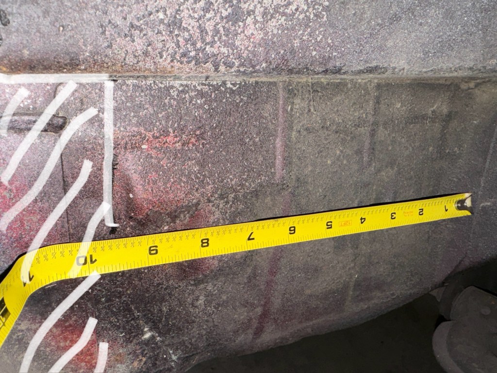
- The rule of thumb for hood vent placement is to go as wide as you can, starting the vent 2″ behind the radiator. The vent should extend no further than 20″ from glass in the center, 15″ on the sides. Bigger is better so long as the vents are behind the radiator and not too close to the high pressure cowl area.
- Use louvers that extend both above and below the hood. The larger the louver, the better the performance. Note that if you race in NASA, they complicate the shit out of it. In ST/TT 4-6 louvers are limited to 3/8″ height above the surface of the hood. In ST/TT 2 and below, hood vent size is unregulated. In ST 3, you need to use the ST 4-6 rules if you choose BTM aero, otherwise use the ST 2 rules. Sigh.
- Add a 1″ tall vertical Gurney flap in front of the hood vent opening (although see above if you race in NASA). A taller Gurney adds more downforce, but there are diminishing returns, so stick with 1”. Note that on a poorly designed hood vent (what Al calls time-attack style), a Gurney flap will only add drag, so don’t bother.
- More is better: More height, more depth, more area. Don’t scrimp on the size of the vents.
- Duct the front of the radiator, so that all the air goes through the rad and not around it. You can use canvas instead of sheet metal, which survives crashes better.
- Seal all gaps in the nose. Air that enters the engine bay bypasses the heat exchangers and pressurizes the engine bay. This creates lift and reduces cooling.