Updated 8/2023 to add Benzing wings and correct an assumption about the Douglas LA203A from Wingmen Aerodynamics.
Airfoil Tools is an amazing website, and was once the primary way I researched wings. When I look at wings, the most important factor to me is the coefficient of lift (Cl); I’m only interested in airfoils that have a Cl 1.5 or higher.
I also look at the efficiency of the wing, which is the coefficient of lift divided by the coefficient of drag (Cl/Cd). Wing efficiency is less important than downforce, because the only thing that matters is the efficiency of the vehicle, and that is typically achieved by using a wing with the greatest downforce. Even if wing efficiency isn’t that important, I wouldn’t use a really draggy wing, so I look for a Cl/Cd of 100 or higher.
So, lift should be at least 1.5, and efficiency should be at least 100. Those are nice round numbers, and easy to remember. I look at these two values at a Reynolds number (Re) of 500,000, because that represents a normal-sized wing at a realistic car speed. For a 9″ wing, 500k Re is 73 mph. For low speeds (or small wings) I’ll look at Re 200k, and for huge wings or really fast speeds, I’ll look at 1 million. But there’s really no reason to look outside of the 200k-1M Reynolds numbers and 500k is a happy medium.
I also set the turbulence value to Ncrit=5 because Airfoil Tools doesn’t allow me to set it any lower (in some cases there’s data for lower Ncrit numbers, but it’s rare.) The default setting in Airfoil Tools is Ncrit=9, and that replicates what the wing would experience in a wind tunnel, and doesn’t represent the turbulent nature of air flowing over a car, nor what’s happening in a race, behind other cars, with cross winds, open windows, and other factors.

The next important factor I look at is how the wing deals with stalling at high angles of attack. I look at this for two reasons. 1) Most cars will go faster with the wing set to maximum downforce rather than maximum efficiency, and 2) car roofs are often cambered and this means air hits the wing at different angles across its length.
For example, on my Miata, if I mount the wing at roof height, the ends of the wing are at 0 degrees, but the angle changes from -5 to -7 degrees along the roofline. If I mount the wing closer to the trunk, that angle increases to nearly 15 degrees. You can read about that and see a video Visualizing Airflow.
Given that air hits a wing at different angles of attack across the wing, at some point along its length, a wing may be stalling. When wings stall, they lose downforce and gain drag. Some wings do this gracefully, with a very gradual falloff in downforce, and others stall dramatically, with downforce crashing and drag spiking way up.
An obvious way around this is to use a wing with a 3D profile, so that air hits the wing at the same angle across the entire wing. You can read about that in my article on 3D wings.
Airfoil Comparisons
Now that you know my criteria for looking at wings, in the rest of this post I examine different wing profiles and give my thoughts on them. I’ve ordered these by Cl, which is how much downforce they make, At the end of this post I’ve included a table with summary values and some parting thoughts.
With all of that front matter and grey matter out of the way, let’s check out some wings!
Clark Y
The Clark Y airfoil (airfoil tools, wikipedia) is distinguished by a flat bottom, or when used upside down on a car, a flat top. Most wings are cambered on both sides, but the flat surface can make it easier to manufacture, and for an airplane, it’s good for training because it has gentle stall characteristics. But as a car wing, the flat top means more drag and less downforce than a wing with a cambered topside. As such, the Clark Y doesn’t quite meet my downforce threshold of 1.5 Cl at 500k, and the efficiency (Cl/Cd) is below 100 as well. Personally, I wouldn’t use this wing, but it would be easy to build.


NACA 6412
MacBeath often cites the NACA profiles as examples in his books, and for good reason, they are easy to understand. The first number in 6412 means percent of camber relative to chord (6%), the second number is where the camber occurs (4 means 40% of the chord), and the third number is thickness (12%). NACA 6412 meets my criteria for a good car wing with a Cl over 1.5 and a Cl/Cd over 100.

I like NACA profiles for another reason: they allow me to change the variables and see what happens to lift, drag, and efficiency at different Reynolds numbers and angles of attack. For example, I’ve read that maximum lift on single-element wings occurs at 12% thickness, and after experimenting with different NACA profiles that are identical in other respects, I know this to be true.
You can also use the NACA 4-digit generator to create your own wing profiles. For example, this is a NACA 9512. I’ve maxed the camber allowed in the tool (9.5%), set the camber further rearward (50%) to increase lift, and used the max lift thickness of 12%. I’m certain this would be a good car wing.

Cambered Plates
Probably the easiest way to make a wing is to cut a metal pipe lengthwise into strips, and then lay two of the curved pieces on top of each other. Put a semi-circular nose on it and weld the three pieces together. This is a cheap and easy way to make blades for small wind turbines, I don’t see why you couldn’t do the same for a car wing. It’s so DIY I want to make one for 24 Hours of Lemons.

You can make these wings in different thicknesses, and at 12%, it has a high Cl of 1.7. However, this wing has a lot of drag and so the efficiency is quite miserable, less than half of my threshold value of 100. Still, for a low-speed wing where drag is inconsequential (autocross), this would totally work. And for 24 Hours of Lemons, it’s better than a snowboard, skateboard, angled plywood, etc.
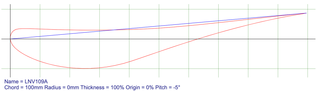
LNV109A – NASCAR COT Wing
NASCAR flirted briefly with car wings, but after 93 races went back to spoilers.

The airfoil they chose was the Douglas/Liebeck LNV109A high lift airfoil. I don’t know what decisions went into that choice, but the numbers don’t excite me. I mean, it would be cool to have one for historical reasons, but I’m not actively searching eBay for one.
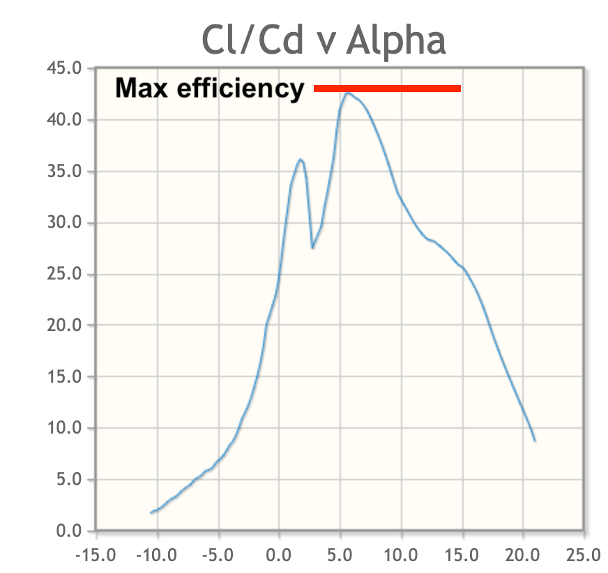
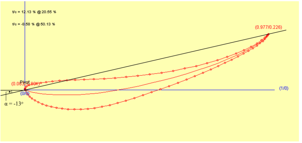
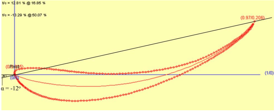
If you look at the Cl vs Alpha chart (which you can think of as how much downforce the wing makes at different angles of attack), you can see the wing has a max Cl of 1.7. Downforce peaks at 12 degrees and then falls off drastically. Compare this to the Clark Y above to see what I mean.

Next, take a look at the efficiency of the wing. Most wings have a bell-shaped curve with maximum efficiency in the middle of the range (say 5 degrees). What’s interesting here is that max efficiency occurs at 10 degrees, with a Cl/Cd is 117. Maybe that’s why NASCAR chose this airfoil shape? If you want a wing that creates close racing at high speed, this would be a good choice. But if your agenda is low lap times, I think there are better choices.

FX 72-MS-150A
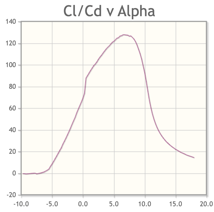
I have three different made-in-China wings, one came as a double wing, the other two are single wings. They are fun for experimenting with, cheap, and disposable. Whoever designed them chose a similar profile for all of them, which is akin to the Wortmann FX 72-MS-150A.

Some of these wings are sold as “universal” and so they are flat on the bottom with two mounting rails underneath. I modify these by adding wood to the bottom and rounding it.

By the numbers, this is a decent airfoil for a car, it makes a lot of lift (1.8) and is very efficient (121). The only drawback is when this wing stalls, it falls out of the sky. This isn’t a wing that you want to set for maximum downforce. Make sure you take into account the downwash angle on the roof.
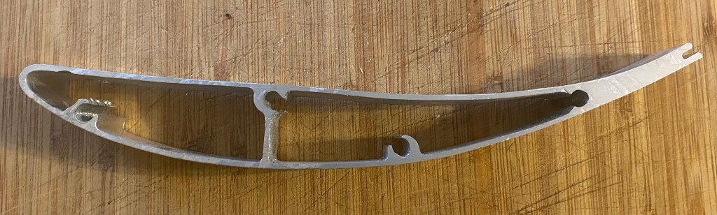
Douglas LA203A – Wingmen Aerodynamics
Wingmen Aerodynamics makes a wing based on this profile. I originally thought it was a Clark Y, but was corrected in the comments section. I’ve seen this wing at a couple different races, and I was immediately impressed with the build quality. It looks very light and feels stiff and strong.

With a max thickness of 15.7%, the wing is on the thicker side, but oddly, it also has less topside camber than most motorsports wings. At around 1.75 Cl, the LA203A, doesn’t make the most downforce, but it’s the second most efficient wing in this article. It also has a very gentle stall characteristic, and should work well behind a cambered roof line, or lower on the trunk lid where the center and ends of the wing are at very different angles of attack. Nice choice, Wingmen.
GOE 464
This is a very thin airfoil, almost potato chip in profile. The only reason I find this aIrfoil interesting is because APR makes a carbon fiber wing using a similar profile. APR’s GTC-300 wing has more camber, but the GOE 464 is close enough to look at some numbers.

The GOE 464 has a max Cl of 1.85, which is a lot of downforce, and the efficiency at 500k almost reaches 100. It’s an interesting wing, but the numbers aren’t blowing me away. Also, it’s so thin that it would be difficult for me to build and make rigid enough, and I feel there are better choices.

Better airfoils
The previous airfoils were all interesting in one way or another, and some can be bought or made pretty cheaply. But all of the following airfoils have superior numbers, and I feel would be better choices for a car wing. Choosing between them is difficult, as there’s always a trade off between lift, drag, and stall. Each airfoil has a niche where it outperforms the others, and I’d be happy with any of them.
Church Hollinger CH10
Any wing that makes around Cl 2.0 is in the category of ultra high lift. The most efficient of these is the Church Hollinger CH10. At 500k, this wing has a Cl/Cd of 132, which blows away the others.

If you look at the data, peak downforce is around 10 degrees. Max efficiency (Cl/Cd) occurs at around 3 degrees, which is where I’d set the wing on a Miata. This would put the angle of attack at 8-10 degrees over the roof, and 3 degrees at the wing ends. Perfect.
I believe that the Wing Logic extruded aluminum wing is a CH10, and if you think it looks a lot like the 9 Lives Racing wing, it’s because they are close cousins in shape. Both airfoils have their maximum thickness at 30% of chord, and their max camber at 50% of chord (measured from the nose of the wing). The difference between them is the 9LR wing has two degrees more camber and 2% more thickness.
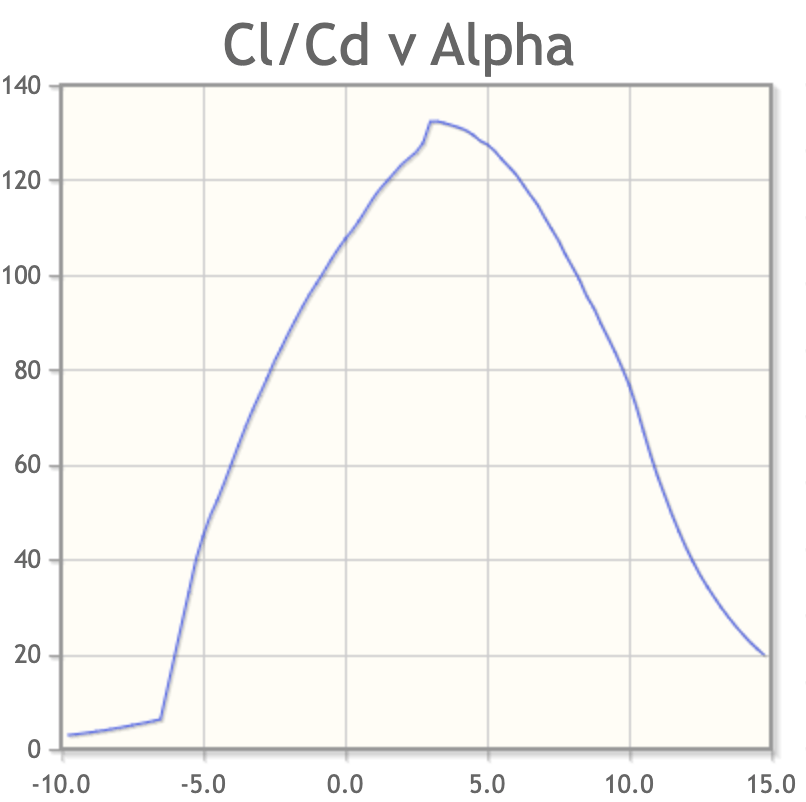
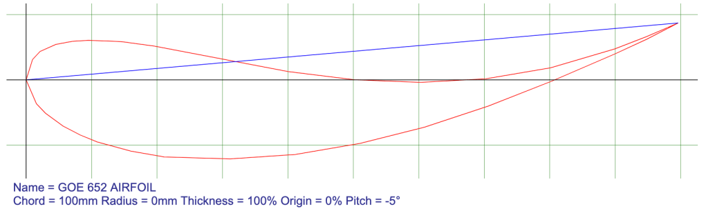
GOE 652
The first thing you notice about this wing is the thickness of the leading edge. It carries that thickness over much of the wing, and the 17% chord thickness is unusually phat. The purpose of that (I think) is to keep air attached at steep angles of attack.
The 652 has a very gradual stall, and should tolerate being set at too steep of an angle. For this reason, I believe this wing would be a good for a car with a highly cambered roofline, or where you have to mount the wing closer to the trunk. In both cases, there are large changes in apparent wind angle across the wing, and this wing won’t care as much as other wings.

This isn’t a particularly efficient wing, and even though it exceeds my threshold value of 100, it does that at a very low angle of attack. However, the high lift of Cl 2.0 puts this wing into elite company. I’d wager this would make a good upper element for a dual-element wing, not just the because of the shape, but because the added thickness would make it stiffer in a smaller chord. I’m definitely making one of these someday.
Eppler 420
The Eppler 420 isn’t as efficient as the CH10, but has slightly more downforce and a gradual stall. It’s a good all-purpose shape, and because it’s thicker, would be a strong contender for either element in a dual-element wing. As an all-purpose wing, it’s hard to choose between the CH10 and E420. The former is more efficient, the latter makes more downforce.
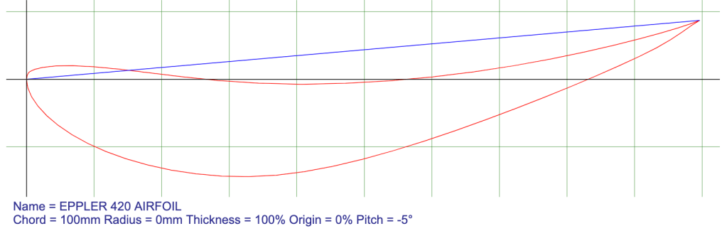
It’s also a pretty good wing for low Reynolds (low speed or small wing). The Porsche Cayman R has a tiny rear wing, and it’s probably not a coincidence that the profile looks a lot like the Eppler 420.
Wortmann FX 74-CL5-140
This airfoil wasn’t on my radar, but in writing this article I looked at every airfoil on the Airfoil Tools site. Glad I did, this one is a keeper! With a Cl that’s nearly the same as the Selig wings, and an efficiency closer to the CH10, this wing sits in rarefied air.
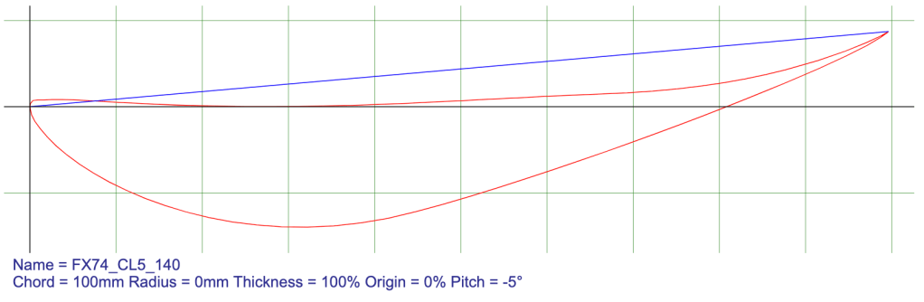
You don’t get something for nothing, and the tradeoff is a steep drop when it stalls. If you want to go after maximum lift with this airfoil, mount it high where the angle of wind doesn’t change much. I’m not sure what’s happening around zero degrees, but I wouldn’t set it there anyway.

I have more to say about this wing after reviewing the next wings. I’m tempted to build one, so stay tuned on that.
Selig 1223 and 1223 RTL
The Selig 1223 and the Selig 1223 RTL are Downforce Royalty. The RTL version is slightly thicker, which results in higher lift and drag. The RTL can be set to 15+ degrees and approaches a Cl of 2.5. That’s huge.
Both airfoils make a lot of downforce, but also a lot of drag, and their Cl/Cd efficiency is less than 100 at all angles. Ergo, I would use this airfoil for low speed or for a car with a lot of power. Those are also usecases for a dual element wing, which might be a better choice if your racing rules allow that.

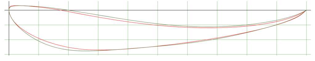
Let’s compare the two Selig wings to the FX74. These graphs are from Re 1M because I plan to use these for a larger chord wing. In the comparisons you can see how the S1223 wings are clear winners in downforce, but the FX74 is far more efficient at Cl 2.25 and below. I’ve drawn a blue dashed line at 2.25 Cl, and you can see that the FX74 has a sweet spot where’s it’s making a lot of downforce without much drag.
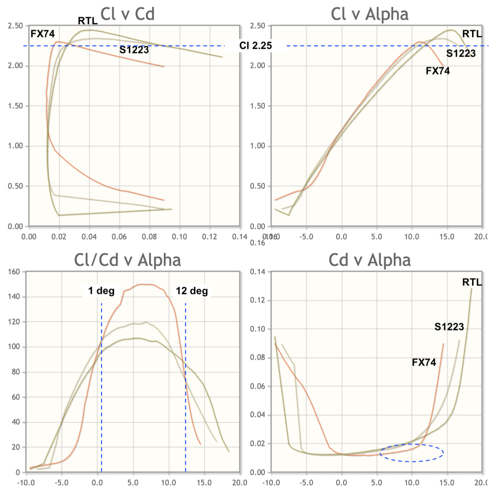
This is how five of the airfoils stack up at 500k Re. I didn’t include the RTL because that’s in the previous charts. I’ve pointed out a few areas that differentiate one wing from another.

Motorsports wings
All of the previous airfoils are aviation wings that have been adapted to motorsports use. Cars don’t (or shouldn’t) fly, and they have much lower Reynolds numbers, and so it makes sense that car-specific wings would be shaped differently.
Indeed, Enrico Benzing did a bunch of research and came up with a lot of different designs specifically for motorsports use. None of these would be particularly good at flying, but they are better choices on cars.
Similar to the NACA wings, the Be-series of numbers tell you about the shape:
- The first two digits are the thickness of the wing, relative to the chord. Aviation wings make maximum downforce around 12% thickness, but cars wings are often thicker.
- The next number is the location of the thickness. Many of Benzings wings have the maximum thickness at 20-30% of the chord. This is supposed to add more downforce.
- The first two numbers after the dash are how much camber the wing has. If you use the Airfoil Tools NACA generator to make your own airfoil shapes, you can’t enter anything higher than 9.5%, and Benzing’s wings are all more than that.
- The final number is the position of the maximum camber, in tenths. More rearward camber generally means more downforce.
Be 183-176 – TCR Wing
As I stated in the NACA wing details, downforce typically increases as you increase thickness, up to about 12%, at which point that trend reverses. But that’s not true for motorsports wings, but even so, this is a very thick wing, the chubbiest in the Be series. This is also extreme camber, I haven’t seen an airfoil with this much.
The TCR regulations state this wing must be 1380mm x 250mm (54.3″ x 9.8″) and you’re not allowed to use a Gurney flap. From the wind tunnel testing I’ve done, I can tell you that a wicker would absolutely help this wing, maybe to the point where it works.

Knowing what I know about wings, I wouldn’t use this one unless I was forced to. Unfortunately, like the LNV109A was with NASCAR, this wing is a homologated part, and all the TCR cars are forced to use it. Worse still, you need to mount it (including brackets and endplates) below the roofline. On a hatchback.
My buddy Josh and I inspected one of the hatchbacks at a wet Grid Life race, and the water left streaks that were like flow-vis paint. You could clearly see where the air was separating on the back third the wing. In my opinion, this airfoil is too thick, it has too much camber, and air can’t stay attached along the entire surface, causing a loss of downforce and increased drag. I could be totally wrong about the TCR wing, and may have to eat my words. One day I’ll test one in a wind tunnel to be sure.
I wrote some additional comments about this wing in my Grid Life recap, and I’ll copy the most salient one here. “Leave it to the people that fucked our asses with diesel-gate to bugger a racing series with a wing that stinks of shit.”
Be 123-125 – 9 Lives Racing Big Wang
Probably the most popular motorsports wing is the 9 Lives “Big Wang”. The shape is essentially a Be 123-125, but with a modification to the rear geometry to support a Gurney flap. The shape is conservative compared to other Benzing wings, and measures in with numbers closer to aviation wings. Never mind that, because it’s a fantastic motorsports wing.
In my wind tunnel testing the Big Wang was second best to the MSHD, and outperformed my S1223. This surprised me considering the amount of research I’d read on low-Reynolds high-lift airfoils; I predicted the S1223 would be a clear winner. Nostradamus I ain’t.
In a research paper on multi-element wings, this shape (or rather a very close cousin of this shape, the 122-125 with thickness 10% further forward) was the best performing main element. So if you are looking at a dual-element wing, this is the best off-the-shelf choice. Or even if you’re looking for a single element wing, it’s pretty hard to beat this on performance.
Be 183-155 – Procar Innvoations
Procar Innovations makes a wing that looks like the TCR, but it has less chord and is less extreme. I measure it up at 183-155, meaning it’s just as thick as the TCR wing, but it has less camber and the location of the camber is 10% further forward.

I tested this wing in the wind tunnel and it was really good, on par with the 9 Lives Racing wing. The end plates fasten with two 8mm bolts instead of four 5mm bolts, and could easily support a double element. The PCI wing doesn’t have a slot for a Gurney flap, but I would rivet on a wicker. My wind tunnel testing confirms that wings with a lot of camber really like a wicker, and this one gained 165% downforce with a 1/2″ piece of angle aluminum taped on top.
MSHD
I didn’t know about this airfoil until recently, as it doesn’t show up in Airfoil Tools, Bigfoil, Enrico Benzing’s Wings, or any other text I own. Because of that, I can’t display the same charts, but I can describe some of the advantages.
There’s a scientific paper on this airfoil making a direct comparison to the S1223 for use in low-speed motorsports applications. The main advantages of the MSHD over the S1223 is an even higher Cl value, softer stall characteristics, and a large range of AoA. To my present knowledge, this airfoil makes the most downforce of any wing listed here. If the Selig wings are the royalty in a deck of cars, then the MSHD is the ace of spades.
Shape-wise, the airfoils are not that much different, but the MSHD has more camber. It almost looks like someone took the S1223 and kept pushing the middle downward until they got flow separation. To plot the wing you can use the values in the spreadsheet.
In my wind tunnel testing this wing produced the best numbers. It also did very well with a Gurney flap. It was fairly easy to build in foam and fiberglas, and I did a DIY writeup on that in another article, but it was hard to get the exact shape because of the thickness of the fiberglass.
Update: An aluminum extruded MSHD is now available from Wing Logic. See my article here. This is the wing to get!
Summary Data
Here are all the wings sorted by cL. For each wing, I’ve also listed the max efficiency, and the angle where that occurs. Note that the fastest way around the track is often right around max downforce, not max efficiency. But efficiency is somehow important for marketing, even if that doesn’t really matter.
| Wing | Max cL | Max cL/cD | Notes |
| Clark Y | 1.45 | 90.2 at α=4° | Clark why? |
| NACA 6412 | 1.6 | 111.3 @ 6.25° | Good reference |
| Cambered plate | 1.7 | 42.5 @ 5.75° | 24 hrs of Lemons |
| NASCAR COT | 1.75 | 113.7 @ 10° | Wing of yesterday |
| Douglas LA203A | 1.75 | 127.7 at α=6.5° | Wingmen of today |
| MIC FX 72 | 1.8 | 121.1 at α=6.75° | MIC-Wing |
| GOE 464 | 1.85 | 97 at α=7.5° | Potato chip |
| CH10 | 1.95 | 132.4 at α=3.25° | Effin efficient |
| GOE 652 | 2.05 | 102.8 at α=2.25° | She thicc |
| Eppler 420 | 2.1 | 106.1 @ 6.25° | Dude, 420 |
| Wortmann FX 74 | 2.25 | 115.5 at α=6.75° | Warts and all |
| s1223 | 2.3 | 97.4 at α=5.75° | DF Queen |
| s1223 RTL | 2.35 | 85.4 at α=5.5° | DF King |
| BE 183-176 | ? | TBD | TCR shite |
| Be 123-125 | >2.35 | TBD | 9LR |
| Be 183-155 | >2.35 | TBD | PCI |
| MSHD | >2.35 | TBD | Ace in the hole |
Wind tunnel testing
This article is theoretical in nature, and lacks real-world testing results. Back when I wrote this article, I hadn’t done any wind tunnel testing. Since that time, I’ve tested many different wings in the wind tunnel, and the results have been… unexpected. For example, I’ve tested the exact same wing on three different cars and have had lift/drag ratios that range from around 3.5:1 to 25:1. So there’s obviously a lot going on here other than just the shape of the airfoil.
The wings tests span two wind tunnel reports, because a Miata and a Veloster N are quite different. Click the button, fill out the form, and you’ll get a link where you can download the reports.

Really cool site. Thanks for posting all this content. I just brought a 2024 Anniversary Edition Supra and ended up hear trying to learn more about wing downforce.
The wing is adjustable and comes with … quote from Toyota below. Any idea what wing its closest too and if the adjustability actually matters going from “street” mode to “track” mode. Wing does not have any obvious match to any of the above lol.
“manually adjustable rear spoiler. The spoiler rises about three inches above the rear decklid and has an adjustment screw that allows drivers to change its angle and influence the amount of downforce being applied to rear wheels.”
LikeLike
I don’t know which wing they use for that, I haven’t even seen an Anniversary Edition yet. But congrats on that, I bet it’s a future collectors item. I would try it at the most extreme mode (high, plus maximum angle) vs the least and see what happens. Pretty cool to see that kind of adjustability in an OE wing.
LikeLike
Hello Occam! Do you have any updates on the TBD?
Do you have any Top mount vs Bottom mount comparisons, or plan to do any; specifically for 9LR, PCI, or other profiles?
Also I’m really debating the PCI over the 9LR because of Bang for buck for my EG Hatch. I really want to minimize drag since I am HP limited, but the car does see speeds between 110-120 in high speed sections, like VIR’s esses. I have a custom made splitter/air dam for the front which seems to be very effective, but throws off the front/rear balance under hard braking; hence I am looking for something that adds rear downforce without introducing a lot of drag.
LikeLike
I don’t have any updates, and I have yet to test wing mounts in the wind tunnel. Hopefully I can do that this year. There isn’t a lot of difference between 9LR and PCI, and it’s likely that where you mount the wing (height, setback distance) will have far more influence on performance that the actual airfoil. Maybe make up some mounts that are X-Y adjustable and see which location is fastest.
LikeLike
What would be the best wing shape for a mixed duty street car? I suppose you’d need efficiency above all else, but without complete sacrifice to downforce. My total goal for the car is actually drag reduction, but I would like a little downforce for stability and fun factor.
LikeLike
I don’t think you can go wrong with any of the low-Reynolds high downforce wings or motorsports wings. 9 Lives and Wing Logic both would work in that application.
LikeLike
Yeah, between those, I think I like the CH10 the best since it seemingly doesn’t require a flap at all… Looking at the charts on that aerofoil site and using the reynolds and ncrit ranges you suggested, it looks like the least draggy AOA within all margins is -2 degrees.
Having that at the ends and letting whatever happens in the middle with my roof (2003 Accord Coupe) happen would probably be more than good enough for a street car. How much area and what width to chord ratio do you recommend? If you know about common sanctioning body limits for different racing categories, I’d like to play it “safe” and still be able to enter into most of them without having to be in a higher class than a street car would be capable in.
Like I said, I’m really not trying to race, or be necessarily competitive if I do, but IF I ever did, it’d be cool to at least not be a useless underdog in a class I don’t belong just because I built one part of my street to over-achieve in xyz aspect or area of performance. You know what I mean?
LikeLiked by 1 person
The shape of the car is more important than the shape of the wing. For example, on a 8th gen Civic a 55” 9LR wing at zero deg was 25:1 lift/drag, which is about 2 hp at 100 mph. The same wing on my Veloster was less than 4:1 L/D. I would get a 55” PCI, 9LR, or Wing Logic, and there will be less than 1% difference between them. The car and position of the wing has much more influence on wing’s performance than the wing itself.
LikeLiked by 1 person
IDK why I can’t reply to your most recent reply to me, but F it. I was going to say that my 7th gen Accord Coupe has a much gentler rear window slope than an 8th gen civic, then ask for position recommendations since you mentioned that was important. I’ve read that the minimum height for a wing above the deck should be equal to the chord length, but IDK if that’s true.
Also, 9LR doesn’t specify the chord length on their “build your own” page so I can’t accurately calculate the wing area in order to conform to (potentially future-applicable) class rules which IDK about, yet, but in the few places I’ve heard about it, the “500 square inches” number has been thrown around a few times. Wing-Logic’s smallest (60″) wing is also almost 600sq-inches, so… Probably the PCI for me unless I can get a chord length from 9LR.
LikeLike
9LR is about 9.2” chord. Wing position should be roof height and 25% overlap over the trunk. Not trying a hard sell, but this is in my wind tunnel report.
LikeLike
Any idea how the Liebeck LD104E profile compares to any of the profiles you tested? I ask since for a long time, this was the only profile allowed in SCCA, Trans Am, IMSA, and Grand-Am. It would be awesome information to compare to more modern profiles, as well as to give people information about how repurposed older wings compare to buying newer profiles
Thanks!
LikeLike
I look into in, thanks.
LikeLike
Hi Mario,
I was able to find the Pakkam MSHD thesis live at this link: https://repository.lib.ncsu.edu/server/api/core/bitstreams/56e62390-f800-4126-af2a-f06873e998d9/content
Thanks for the great article!
-Matt
LikeLike
When speaking of the AoA of an airfoil, about which axis is it being rotated? For instance, you mention that the CH10 wing would be ideal for a miata at 3* AoA and in the image provided you have a listed pitch of -2. Am I to suppose that it’s current position, with a pitch of -2, is to be an AoA of 0 or 2? Would this be rotated about the origin, the center line of the wing, what do?
Amazing website and information. Learning quite a lot. So much so that I’m going to 3d print a wing, and want to ensure my profiles are correct.
LikeLike
When I wrote this article I hadn’t tested this in the wind tunnel. But having just done that, you’ll want to use between zero (horizontal) and 5 degrees (pitched forward).
LikeLike
The links to the MSHD wing appear to be dead, do you have any more references to it?
LikeLike
Oh damn, I’ll have to look
LikeLike
Hi there! Evan from Wingmen Aerodynamics here. First off, as a tiny, part-time outfit run out of half of my two car garage, it is very cool to run across a reference to our wings out in the wild.
Quick correction on the speculation of our airfoil profile; it is not a Clark Y. In the initial design of our wings, we actually evaluated many (most) of the “royalty-level” profiles mentioned in this article. We ended up settling on a slightly modified version of the Douglas LA203A airfoil. It was easier to manufacture than many others, and when looking at Re range for our target market (budget endurance racers), it met the performance parameters we were targeting quite well.
LikeLike
I’ll update the article. Your construction looks excellent.
LikeLike
Appreciate it! We put a lot of effort into that.
LikeLike
Awesome article, written well as always. Now I have a long day of referencing this article to better tackle aero in my slow car.
Thanks, you da man.
LikeLiked by 1 person
More data on this profile here : https://www.miataturbo.net/race-prep-75/active-rear-wing-test-74913/page10/#post1186653
(My last comment I promesse ^^’)
LikeLike
That’s a long thread, I finally got through it. Lots of great info on active aero, which is something I haven’t experimented with yet. I was going to try an active spoiler, and a double element wing DRS style. I’m interested in what else went on in the last 8-9 years since that thread was active.
LikeLike
*3d printed wing
LikeLike
I use 3d wing (looks like ch10) since one year on my miata and everything work perfectly.
I m going to make new one, with the Jack Olsen’s profile naca 63-520M (more details here : https://forums.pelicanparts.com/porsche-911-technical-forum/302014-poor-mans-aero-building-your-own-wing-many-pix.html)
This profile was draw for him by an aerodynamist (Peter bull).
Thanks a lot for sharing your knowledge it s really interesting
LikeLike
Thanks for writing this. It has inspired me. I’m slowly putting together a car to replace my current endurance race car and since LuckyDog has no aero restrictions I want to really lean into aero. I actually have a 9 lives wing that I was going to use but now I think I will sell.
I have built a wrapped foam care wing with a friend before and wasn’t crazy about the results. It had a spar in it but the load path from the mounts through the wing wasn’t great. Reading this kicked me off on some internets scouring to understand how folks build carbon wings. After finding a picture of the guts of a Bimmerworld wing, I think I can replicate their internal spar design using some 3d printed molds and assembly tooling. I think I am going to build an fx74 wing with a 12.5” chord. I have printed up a small process trial mold for the leading edge geometry. If that goes well, I will print the molds to make a short section of the wing before I commit to the 1-2 weeks of printing to make all the molds for a full sized wing.
LikeLiked by 1 person
I have seen two 3D printed wings, you might ask them how they did it and about any problems they had. Seek out Bronson Mcnemar (BroFab) and Alyssa Merrill on FB. I used to race Lucky Dog when I was on the west coast, that’s my favorite series. Good luck.
LikeLike