Engineers design cars with the sound belief that people will drive them around with the windows closed. But in high performance driving, we sometimes have to roll then down.
In Europe, they keep the windows closed for racing and track driving because it’s safer. The reasoning is, that in case of a rollover, the car is stronger with the windows closed. And the closed windows also keeps insects, tire debris, and other shit from hitting the driver.
In the USA, we race and do track days with the windows down because it’s safer. The reason being that after a crash, we may need to extract someone through a window if every single door on the car no longer works. It isn’t exactly logical, but that’s our time-worn tradition.
In the USA, we have another time-worn tradition, which is to let people who have a lot of money bend the rules and do whatever the fuck they want. And so if you buy a Porsche 911 GT3 Cup, which has Lexan windows that are fixed in place and don’t roll down, that’s OK, you can keep the windows closed and do point-bys with your turn singals. Nevermind that anyone who can afford a Cup car can afford a spare set of doors with no windows….
And so I’ve wondered about the aerodynamic effects of open and closed windows, and how much of an advantage these entitled rule dodgers have when they bring a Cup car to a track day.
Calculator results
Everyone who has experienced buffeting when they open their car window at speed understands that open windows causes turbulence. From this you can conclude that there must also be an increase in drag, and if your car has a rear wing, a loss of rear downforce. But how much?
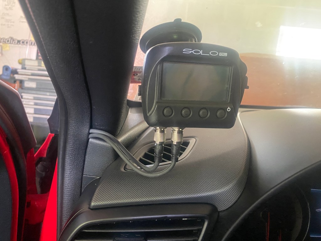
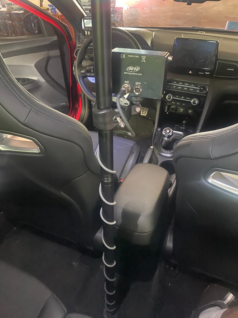
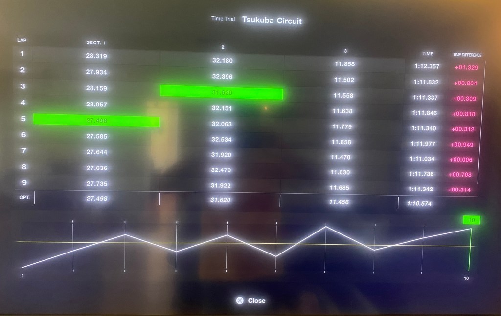
At first I tried to figure this out with an online calculator, and then later tested open vs closed windows in the A2 wind tunnel. If you skip ahead to the wind tunnel results, the only thing you’ll miss is that the Veloster N seems to be better than most cars, and even most race cars, with respect to open windows. How did I figure that out?
I used the Drag and lift calculator from HP Wizard. This aerodynamic estimation tool calculates the drag and lift of your vehicle based on its body shape. I’ve gotten very close to real-world values using this tool, it’s pretty dope.
To use the tool you click on the little pictures that describe the various shapes of your car. When you’re done, you’ll have a close approximation of drag and lift. You can also use this tool to do things like change your sedan into a fastback and see how much that reduces drag. Or in this case, open the windows and see what happens.

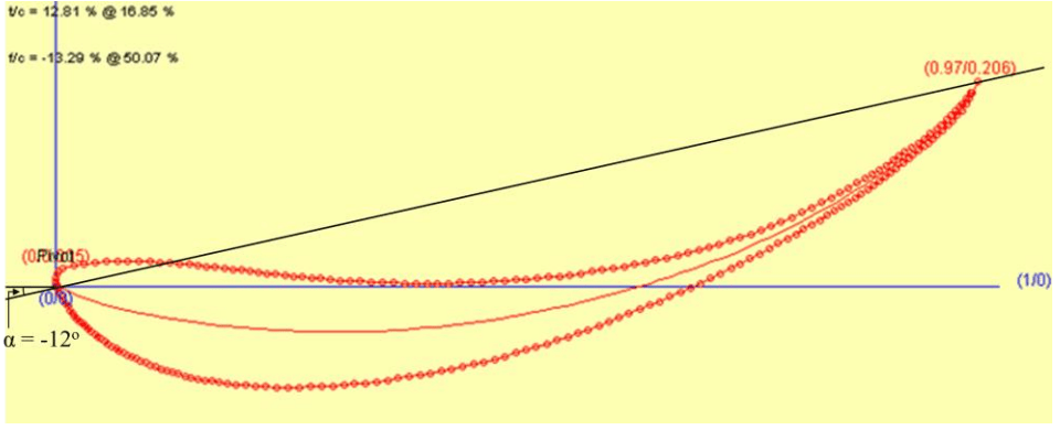
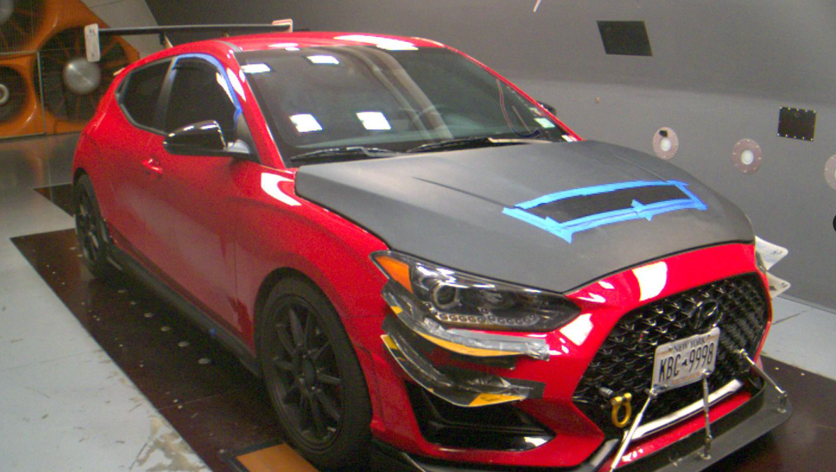
I built my Veloster N in HP Wizard and the tool says it should have a drag (cD) of 0.357 and positive lift (cL) of 0.15. This is a fair approximation for a hatchback with a similar shape. However, in the wind tunnel, my Veloster N had a drag coefficient much higher than that, at .421. What the fuck?
| I’ve seen no official figures on cD for the Veloster N, but various people online have stated that it’s around 0.33. Manufacturers have been known to change ride height and optimize things in other ways to fudge the numbers, but there ain’t no way a Veloster is getting close to 0.33 cD. |
Most production cars generate lift, because they are longer on the top than on the bottom. That shape is akin to an airplane wing, and so cars typically lift at speed. Cars with more streamlined shapes, like coupes and fastbacks, generally have even more lift.
To counteract lift you add devices like airdams, splitters, spoilers, and wings that create downforce. The byproduct of downforce is drag. And guess what? The Veloster N creates downforce.
Yep, believe it or not, the Veloster N has a cL of -.027, meaning it makes downforce, straight from the factory. This is normal for a Ferrari or Porsche, but very rare for a production car. And for a hatchback? It’s the first I’ve ever heard of it.
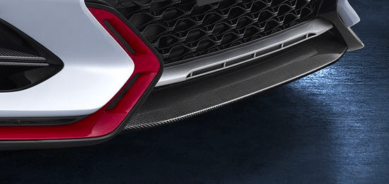
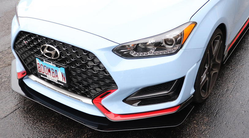
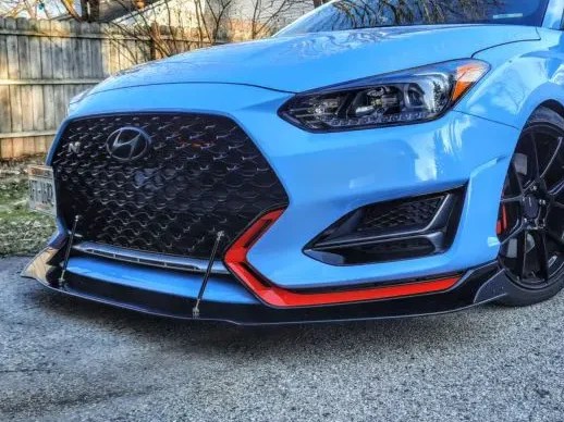
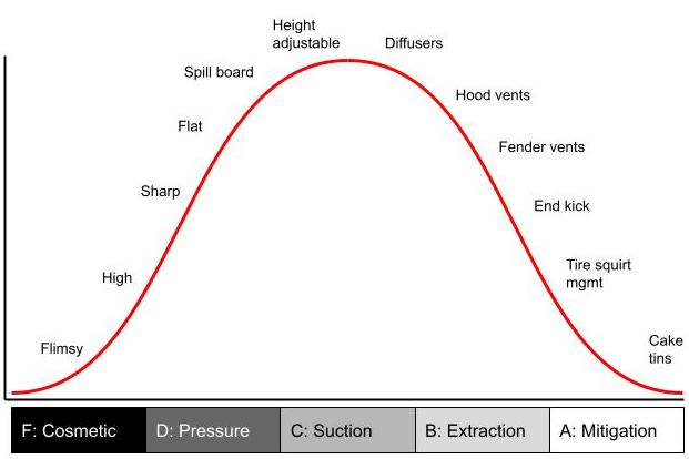
When you create downforce via suction you can return a high lift to drag (L/D) ratio, but when you work only from the pressure side, it’s much less efficient. The Veloster doesn’t have a proper rear wing or splitter, and generates downforce primarily through areas that hold positive pressure. All of those angled surfaces on the front bumper fascia plus that funky spoiler combine to make downforce. But this also results in a lot of drag.
To go back to HP Wizard for a minute, it uses a default value of .15 for lift (cL) for all cars. If we give the downforce-generating bodywork an inefficient but fair 2:1 L/D ratio, then we can add .059 to the .357 drag that HP Wizard estimated, and we get a .416 cD. So that’s pretty close to the Veloster N’s measured .421. That’s with the windows closed, of course.
So now that we have a fair representation of drag, let’s see what happens when we open the windows. HP Wizard has two options for that: race car and production car. The race car version is more streamlined, and is less affected by the open windows.
| Configuration | cD | Delta |
| HP Wiz closed windows | .357 | |
| HP Wiz open windows (race car) | .385 | .027 |
| HP Wiz open windows (prod car) | .404 | .047 |
Keep those values in your head: An additional cD of.027 (or 2.7 points) is the additional drag on a race car, and .047 is the amount of drag on a production car. The Veloster N is better than that, but we’ll geto that in a moment, first we must also discuss downforce.
The problem with opening your car windows isn’t just that it adds drag, it also reduces rear downforce. The net effect is a worse L/D ratio. But how much worse?
Well if we look at HP Wizard, it says there’s no change in downforce when you open the windows, the cL stays a static .15 (meaning positive lift) no matter if the windows are open or closed. Now HP Wizard is a simple calculator, and perhaps the values are too variable to be meaningful. So I’ll give them a break. Luckily, I got this information from the wind tunnel.
Wind tunnel results
In the wind tunnel, the data shows that opening the front windows results in a significant 15% loss in rear downforce. What’s interesting is that the percentage of loss is the same with either a spoiler or a wing. However, because a rear wing might generate on the order of 400 lbs of downforce, a good 60 pounds of that is sucked out when you open windows.
Whether using a spoiler, wing, or OEM bodywork, the result of this 15% rear downforce loss is that that the aero balance shifts forward. For example, on my stock-bodied Veloster N, opening the windows at 100 mph results in a loss of 5.6 lbs of rear downforce, and with that, a gain of 4.8 lbs of front downforce. (This is normal: gains at one end of the car often result in losses on the other end.) This isn’t a huge change, but the car will now start to shift to oversteer slightly at high speed. Not so good.
Now let’s talk about what happens to drag. Recall that HP Wizard predicted that the race car would gain 2.7 points of drag (.027 cD), and the production car would gain 4.7 points of drag, with open windows. The Veloster gains only 2.3 points with open windows!
| Configuration | cD | Delta |
| HP Wiz closed windows | .357 | |
| HP Wiz open windows (race car) | .385 | .027 |
| HP Wiz open windows (prod car) | .404 | .047 |
| Wind tunnel closed windows | .421 | |
| Wind tunnel open windows | .444 | .023 |
This is surprising, because HP Wizard is a fairly accurate calculator. So if we go along with that, according to the data, the average production car will lose about 7 hp at 100 mph when it opens the windows, while the Veloster N loses only 3.4 hp. (Side note – the drag loss was the same with OEM spoiler or a wing.)
At this point you might be imagining how your car will react with open windows. I’m sorry to say, it’s almost certainly going to be worse than mine. 1) Because the Veloster doesn’t lose a lot of drag with open windows, we can conclude it’s loss of downforce is also less than other cars, 2) The hatchback body style is likely to be less affected by the open window turbulence, 3) the short 135cmm wing doesn’t stick out into airflow as much as other wings, and will be less affected by open window turbulence.
On a car with a less efficient body shape, like a hardtop Miata, I’d guess that the wing loses 25% of its downforce between the open windows and the compromised shape of the canopy, and probably a great deal more drag as well.
And these results come from linear airflow in a wind tunnel. When the car is cornering and in yaw, the outside window will have even more air shoved inside, and I’m not sure what that will do for drag and turbulence, but it could be a lot worse.
Open window improvements
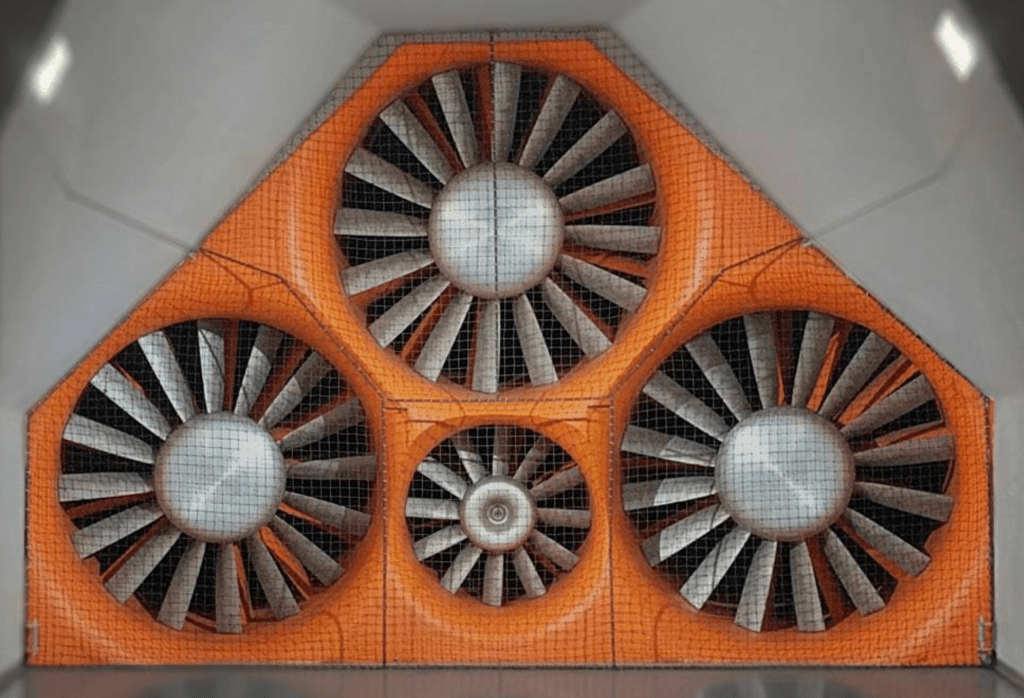
Given that open windows reduce performance, it would be useful to minimize the amount of drag and turbulence from them. There are several ways you might do that: by addressing air at the front of the A-pillar, helping airflow re-attach at the B-pillar, reducing the size of the window openings, or blocking the air as much as possible using a window net.
A good source for ideas is NASCAR, because they race with the windows open and at such high speed they need to employ all the tricks. For example, their window nets have more fabric than holes. Do you think this is for safety or for aero?

A pillar
The relationship between the width of the A and B pillars is important. If the A pillar is wider than the B pillar, less air will go in the cockpit, as air can more easily jump the window gap and reattach at the B pillar. On older cars, the A and B pillars are often the same width, and you’d guess that open windows are slightly worse.
On convertibles with hardtops (Miata, S2000, etc), the B pillar is wider still, because it has to cover the gap where the convertible top stows away. As such, the B pillar sticks out into airflow and turns the cabin into a parachute. The result is lot of turbulence, drag, and loss of downforce.
To help air jump the window gap, you could do something to widen the A pillar, or add a wicker on the quarter window frame. This would move the stagnation point outward, and that should help air pass by the gap. This is a fairly easy modification, and I’ll have to wind tunnel test that in the future.
Another idea I’ve seen is to add vortex generators in the same location. VGs are fairly draggy themselves, but they can reduce drag overall if they delay flow separation.
In my testing, I found that vortex generators on the roof were particularly bad; they caused a loss of 5 hp (at 100 mph) due to drag and reduced the rear wing’s downforce by 28%! I haven’t tested VGs on the quarter window frame, but my guess is they are going to have a lot of downstream losses, and won’t work as well as a simple wicker. But this would be an easy one to test in the wind tunnel, and put to rest a lot of silly speculation.

I asked my aero sensei Kyle Forster if there was anything I could do to mitigate losses from open windows, and he said there’s more to be gained by smoothing the air at the B pillar than doing anything with the A pillar. So there you have it from a F1 aero engineer, maybe don’t waste too much time on the quarter window.
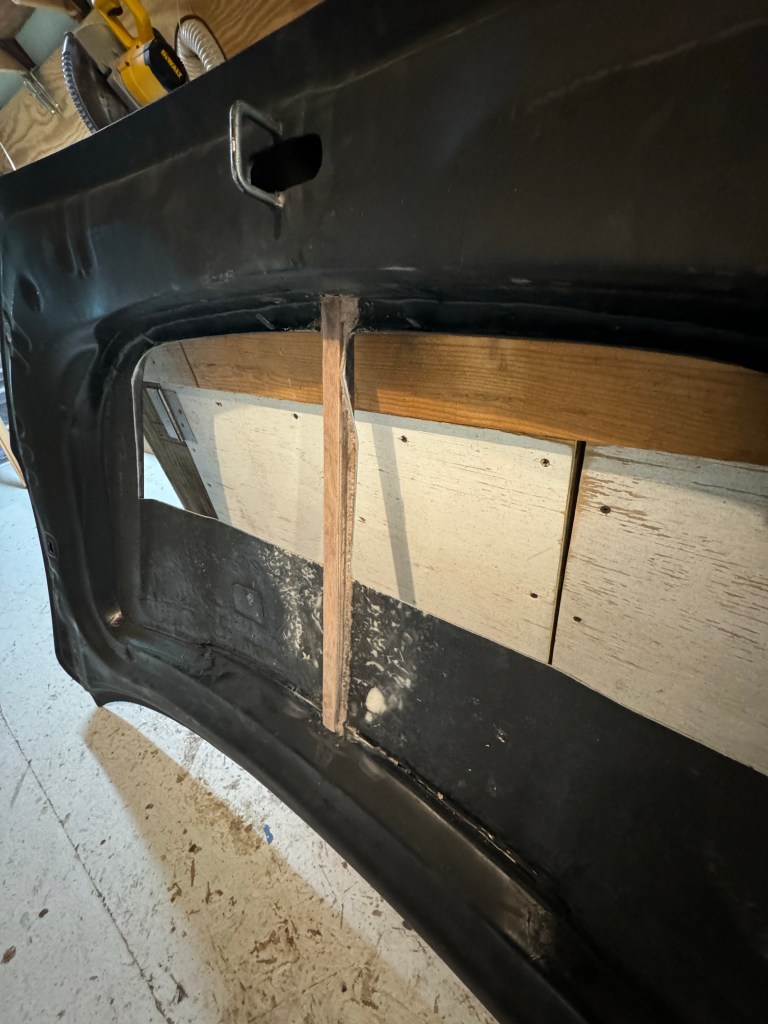
B pillar
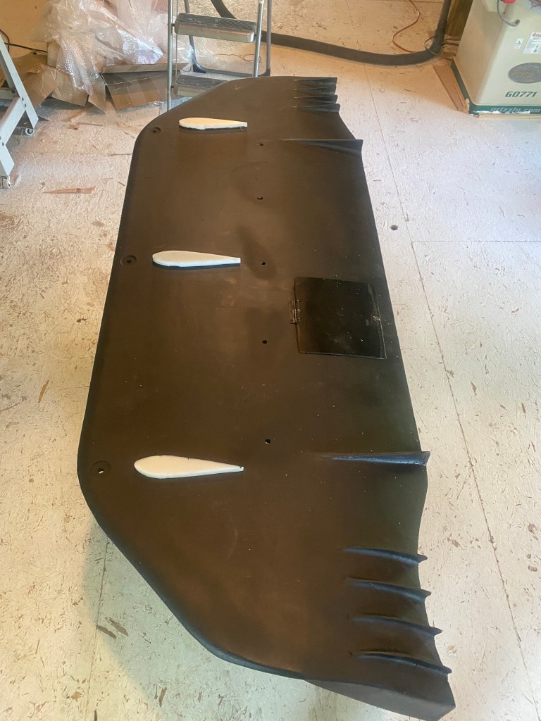
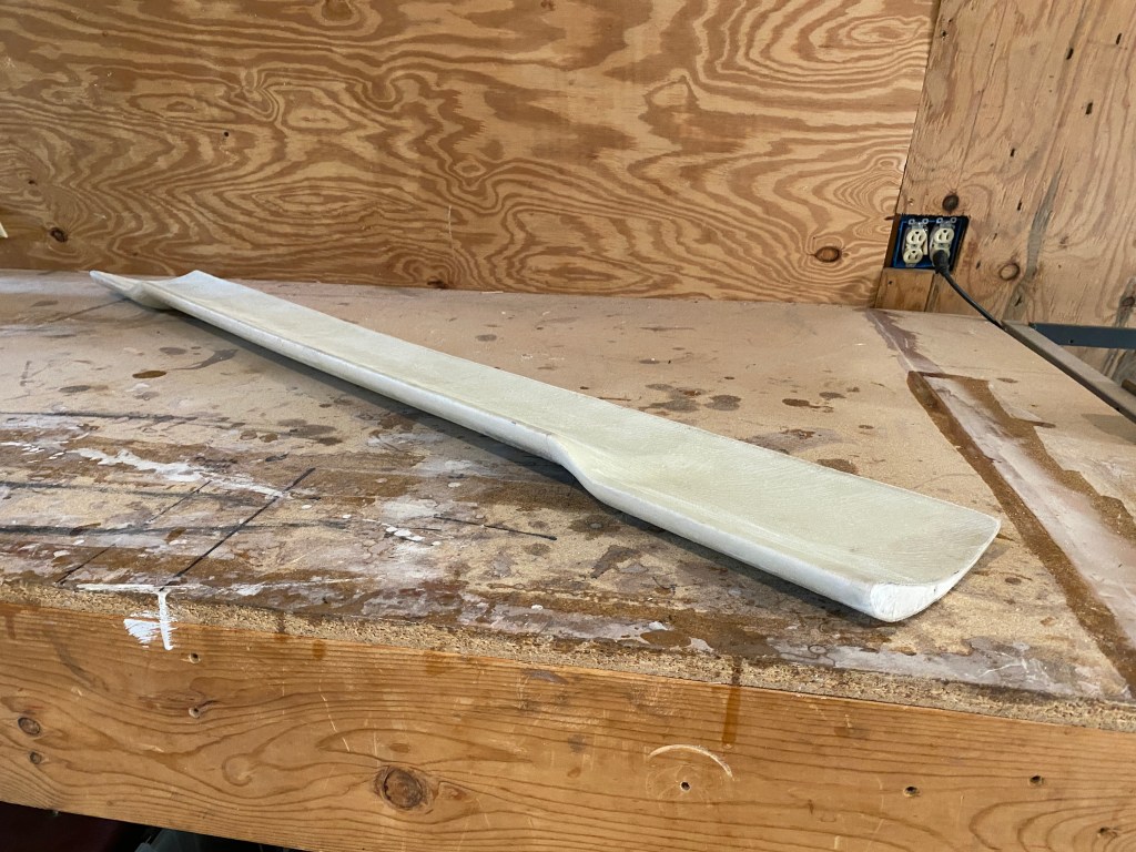
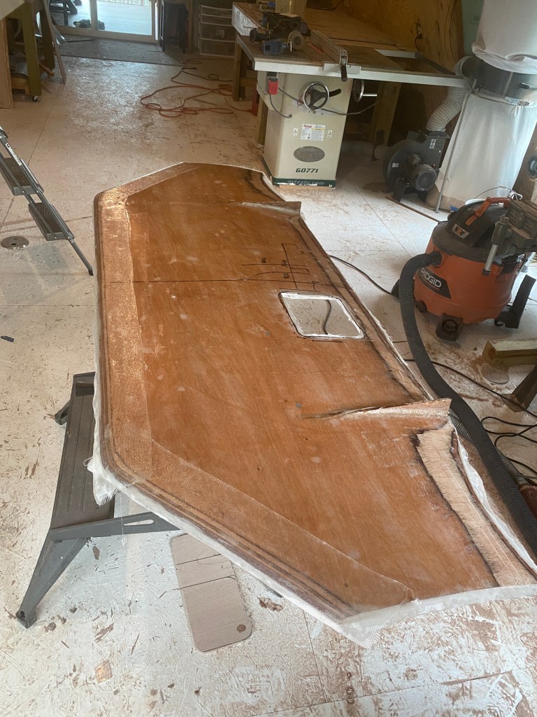
If you look at any NASCAR stock car you’ll see a lot of rounding on the B-pillar, which extends inside the cockpit slightly, behind the driver’s head. I did the same thing with my Miata fastback, trying to scoop air that was in the cockpit and coax it out the back of the window.

I’ve written about my fastback Miata a few times here; it reduced drag by 15% and increased rear downforce by 130% compared to the OEM hardtop. Those are crazy good numbers for just a top.
In the past I had attributed most of that to the improved backlight angle, and opined that the narrower B pillar was potentially part of the performance. But knowing what I know now, I believe that the narrower B pillar has more to do with it than I thought. It’s the only way to explain how the L/D ratio went from 2.11 to 2.97. That’s an insane improvement from simply changing the shape of the roof.
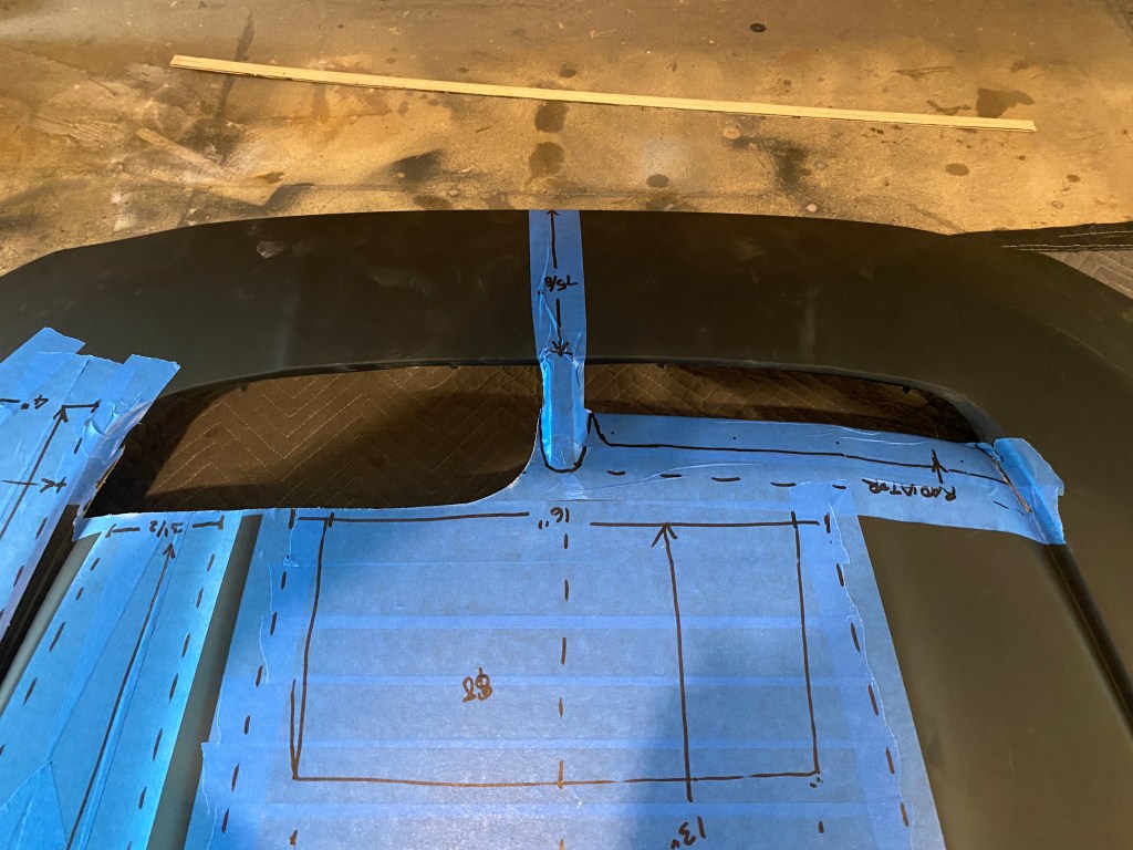
Roofline junction
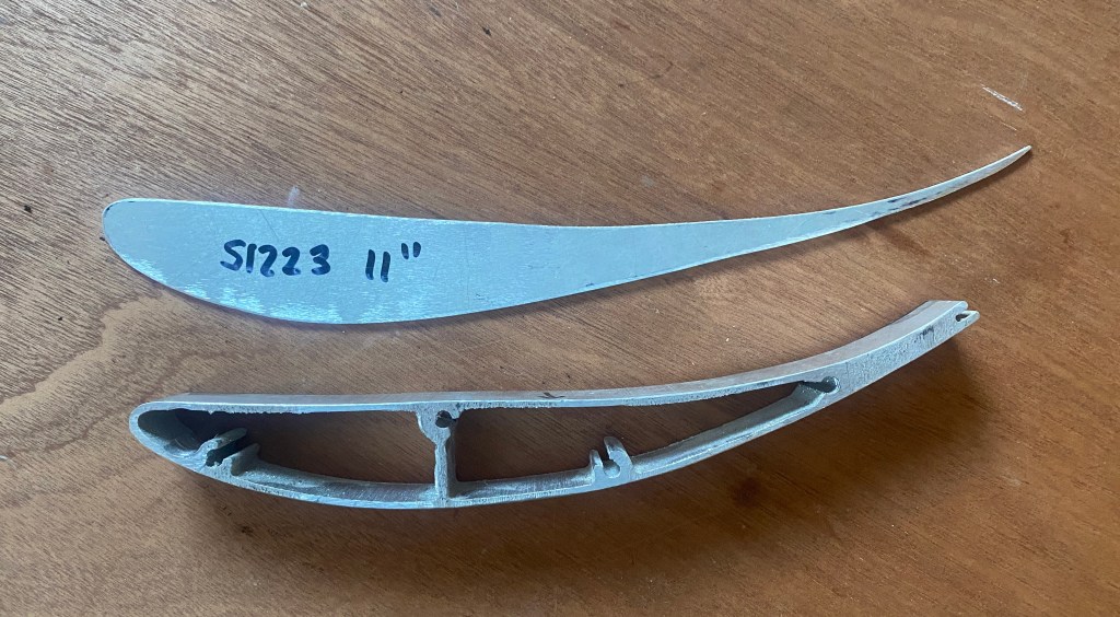
The one thing I tried in the wind tunnel that would affect open windows was the addition of WellVizor wind visors. These reduce the top edge of the window opening by 1″ at the front, gradually expanding to about 2″ at the rear. That’s not a lot of area, but it turns out to be a very significant area for turbulence.

The visors attach nearly flush with the body, and don’t bulge out like some I’ve seen, nor do they cover much of the window. So imagine our surprise when the two little pieces of smoked plastic reduced the effect of open windows by half! In practical terms of 100 mph, that means a gain of about 1.5 hp due to drag reduction, while also gaining 7% more rear downforce.
Given that these simple visors reduced open window losses by that much, I can conclude that most of the turbulence comes from the top of the window. Ergo, you can do whatever you want to the A pillar or B pillar, and it won’t amount to what you’ll get by smoothing airflow and/or reducing window size at the roofline junction. At least on this car.
The only downside to the window visors is you may hit your arm on it when you signal a point-by over the roof. However, they are flexible and bend out of the way. This is especially important if you had to exit the car window with your helmet on.
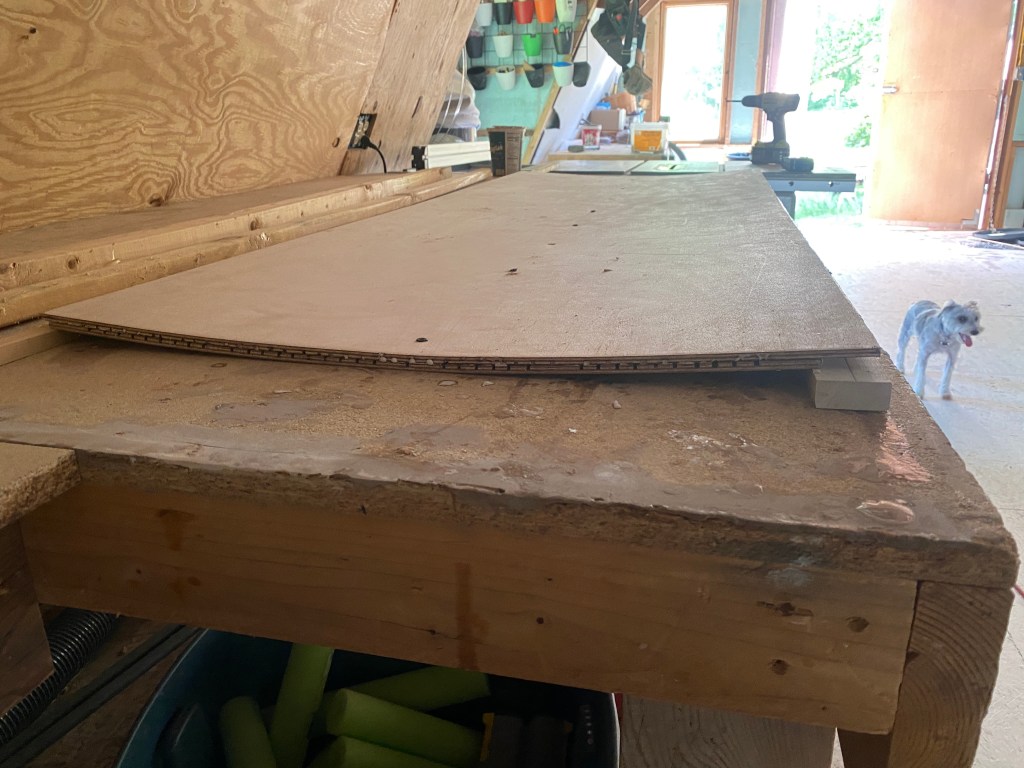
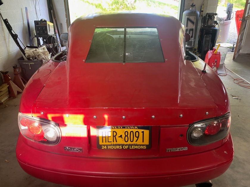
I can’t fit window visors to my Miata because there’s no window frame, so I modified my fastback roofline to have a lower opening, and added a drip edge hoping this will reduce air going in the cockpit.

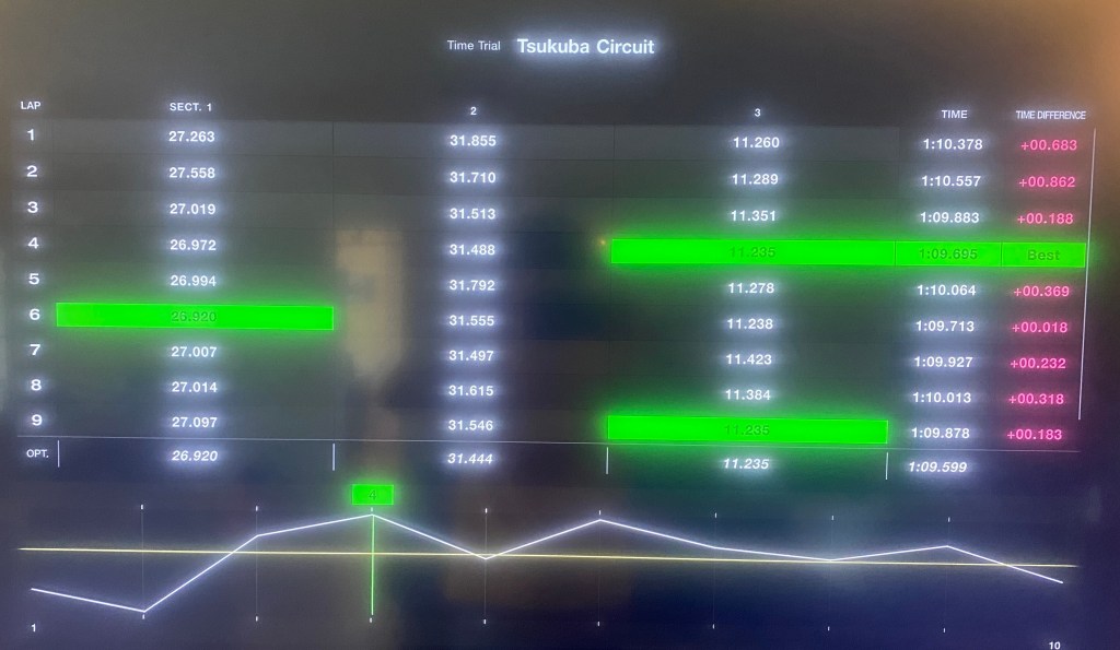
Racing simulations
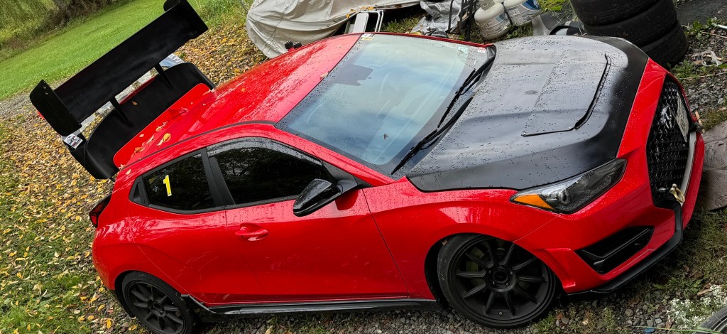
Now that I have all the data, I can get back to the question of how much of an advantage the Cup Cars with their fixed Lexan windows have. To find out, I’ll run a few simulations in OptimumLap, comparing cars with open and closed windows. I’ll do this for the base model Veloster, and also one with a wing, because that will have larger losses. I’ll also throw the window visors in the mix to see what they do.
I’ll run the simulations at two different venues, the autocross track from 2010 Solo Nationals and Lime Rock. I use these two tracks because they represent opposite sides of the aero spectrum, and have lap times that are quite similar to each other. So this is a good way to see the relative benefit of aero on a slow and fast track.
For the simulations I’ll use the following values for the Veloster: 3250 lbs, 234 hp, long-G .95, lat-G 1.2, and simply change the cD and cL to match the different builds. The aero car is just a splitter and wing, and represents a low effort build, so don’t get overly excited about it’s lackluster performance.
| Configuration | cD | cL | Autocross | Lime Rock |
| OEM body, windows closed | .421 | -.027 | 62.42 | 61.83 |
| OEM body, windows open | .444 | -.024 | 62.43 | 61.92 |
| OEM body, wind visors | .434 | -.026 | 62.43 | 61.88 |
| Aero body, windows closed | .503 | -.495 | 61.98 | 61.00 |
| Aero body, windows open | .527 | -.457 | 62.03 | 61.18 |
| Aero body, wind visors | .517 | -.474 | 62.01 | 61.10 |
The results show that whether you have open or closed windows on an autocross course, it won’t make a difference. It doesn’t even matter if the car has aero.
On a proper race track like Lime Rock, a Veloster with the windows closed would go .09 seconds faster per lap than one with the windows open. On the mildly aero’d car, that would double to .18 seconds per lap. Lime Rock is a short track, and so on longer track with a 2-minute lap, a car with closed windows are gaining .36 seconds on the rest of us. That’s not as much as I thought it would be, but it’s still significant.
The budget solution is to put window visors on your car, and these resulted in a 1/10 of a second advantage at Lime Rock, on the aero car. If this seems like a very small number, think about this: in a two-hour endurance race stint, the rain visors would gain almost 12 seconds over a car with open windows, while simultaneously reducing fuel consumption.
Conclusions
Open windows are a drag, but you can mitigate losses by using simple tricks like modifications to the A and B pillar, or addressing the roofline junction window visors. WellVizors are just one of several different manufacturers that make rain/wind guards, and it might be that the more bulbous versions work better that the streamlined ones. There’s more to experiment with here, and the results could vary widely, depending on the car. (Note that you can contact WellVizors directly and order just the fronts at a great discount.)
The Veloster didn’t suffer a lot from open windows, and it’s just one more way that I’m constantly surprised by its design and performance. Most cars will certainly perform worse with the windows down.
Convertible cars with their shitty hardtops are particularly screwed by open windows by an exaggerated parachute effect at the B pillar. Furthermore, they don’t have window frames, and so you can’t even attach window visors! But there are ways around this if you put some creativity into it.
As for the moneybags bringing their 911 Cup cars to track days, the closed (fixed) windows aren’t actually that big of a deal. Most of the P-car owners can’t drive worth a shit anyway, and they need every advantage they can get.
| If you enjoyed reading this article, check out my wind tunnel report. It’s over 50 pages of similar data, but goes over many more pieces of aero, and to a much greater depth. |