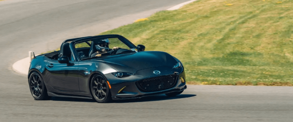
If you read Grassroots Motorsports, you’re probably familiar with Andy Hollis’ Triple Threat MX-5 Miata. This is an ND2 Miata that has evolved over time to showcase the benefits of small, incremental improvements to suspension, safety, and brakes, while serving as a test bed for various wheel and tire combinations. These basic modifications enhance performance on track without sacrificing much comfort on the street. I’ve followed this GRM build, this has been much of my philosophy with my ND Miata too – take a simple approach to modifications to have an HPDE and time trial competitive car that can still be enjoyed on the street.
Having owned several older Miatas over the years, I now strongly prefer mine to have a warranty, cold AC, Apple CarPlay, and 40 mpg fuel economy. I roll up to the track, turn a few knobs, put down a lap, and drive home in relative comfort. For me, I consider this to be the sweet spot for enjoying motorsports in a relaxed capacity. No wheel-to-wheel racing risks. No dedicated race car towed with a truck and trailer. A casual approach with a dual-purpose car checks several boxes, keeping costs relatively low. But when time trial competitors take a more serious approach, sometimes it requires stepping outside of that comfort zone.
When I started running time trial style events at Pineview Run a few years ago, I relied heavily on “cheater tire” mechanical grip and driving my ND1 Miata in a way that only an extended drivetrain warranty and a AAA membership could permit. I didn’t want to potentially sacrifice reliability with additional horsepower and I didn’t want to disfigure stock body panels with lips, vents, and wings.
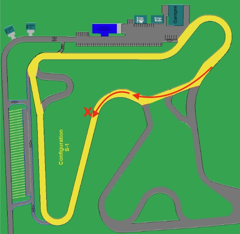
During this phase of aero reluctance, I still managed to get good enough at the short course to set a class record, win my class, and the overall Challenge Cup series championship for 2021. Pineview (at least in its legacy short course configuration) is a very Miata-friendly track. The past three champions can confirm.
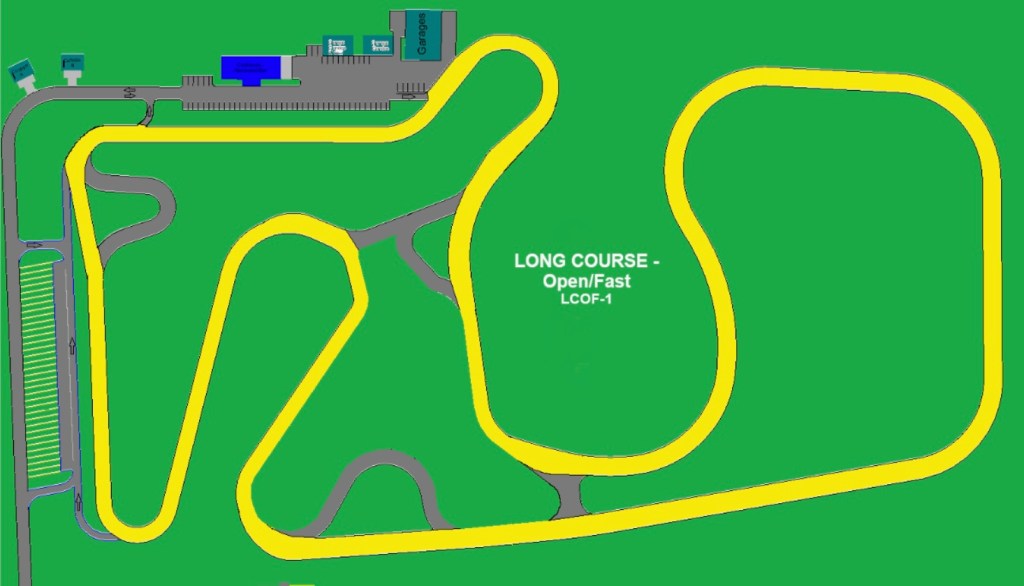
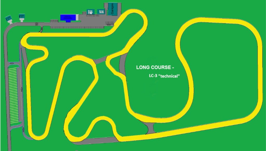
I’ve since moved back to central Florida and consider the Florida International Rally and Motorsport Park (or better known as the FIRM) as my new home track. The FIRM is a fun and challenging track in its own way, but makes me really miss having some elevation changes. For the most part, the layout favors horsepower, not Miatas.
The main straight is more than three times longer than the one on Pineview’s original 1.1 mile short course. There’s just more speed available to make a strong case for aerodynamic assistance. And that’s what many of my TT5 class competitors have opted for – big wings. When you see these wing-equipped cars running nearly four seconds faster, you realize it’s time to stop being so stubborn about aero.
At this stage, I had a stiffer front anti-sway bar and a set of Sakebomb Garage tuned Ohlins DFV coilovers – which I give most of the credit for shaping what a dual-purpose ND2 Miata should be. The stock dampers and springs on NDs just make them downright hazardous. The softness can be masked with a good 200 treadwear tire, but quality coilovers absolutely transform these cars. Eliminating the unpredictability of stock suspension allows the car to communicate and quickly inspire more driver confidence and control. If you’ve ever been at a track day and seen an ND do a tank-slapper following some oversteer correction, I’ll bet it was on bone stock suspension.
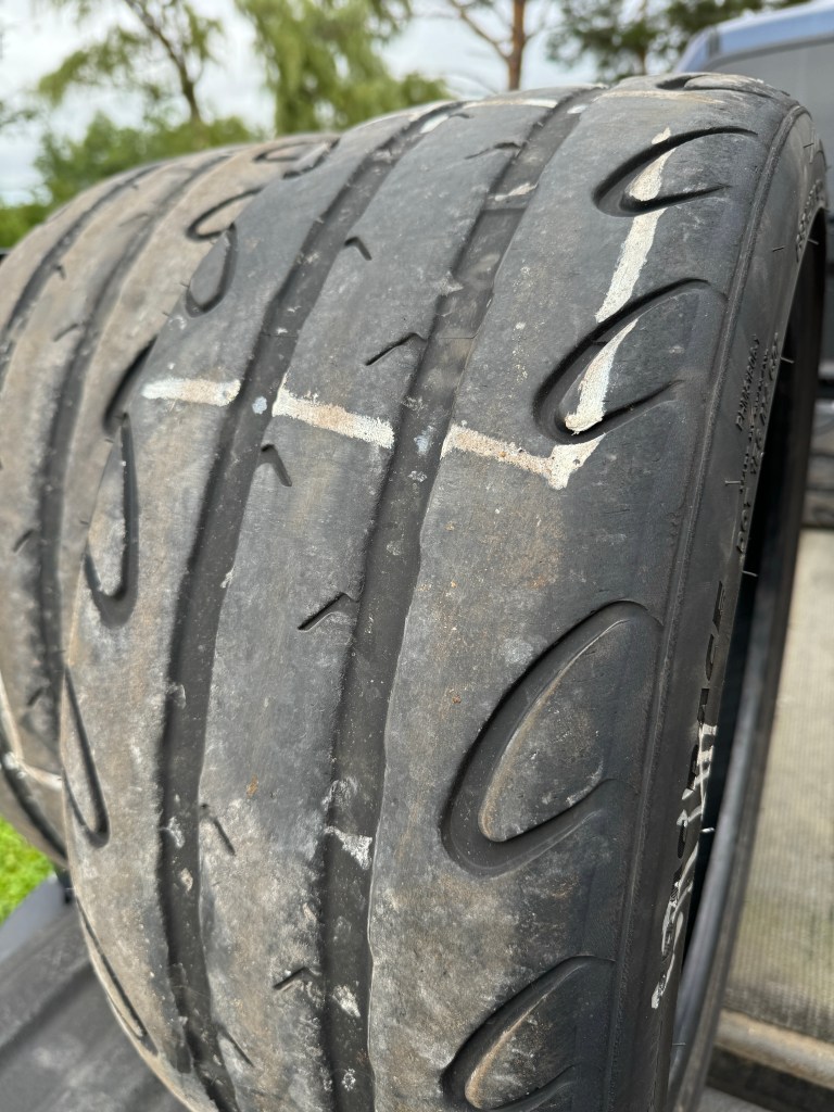
During pre-season testing at the FIRM, I barely broken into the 1:19s on 15-inch 225 Yokohama A052s. I knew the addition of aero would be necessary to chase some of the faster cars in my class, but I still wasn’t quite ready to start drilling holes in my three-year-old Miata.
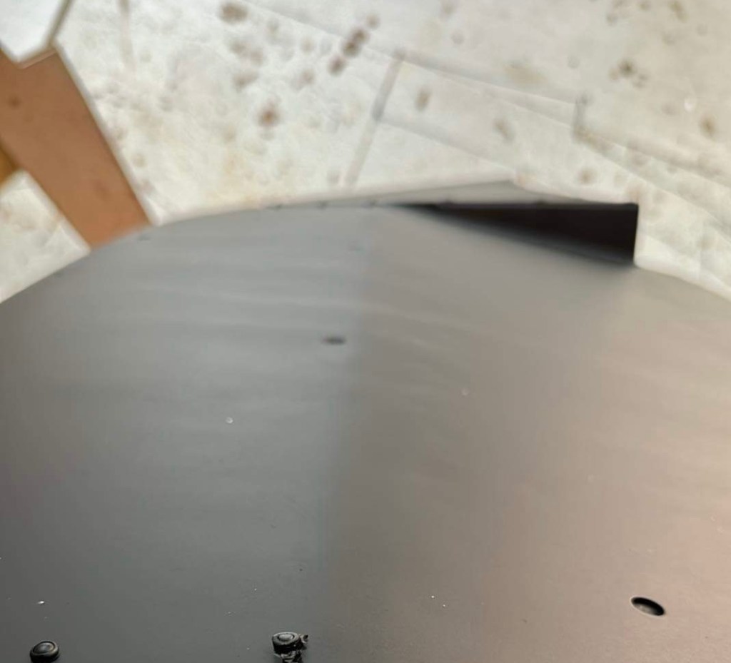
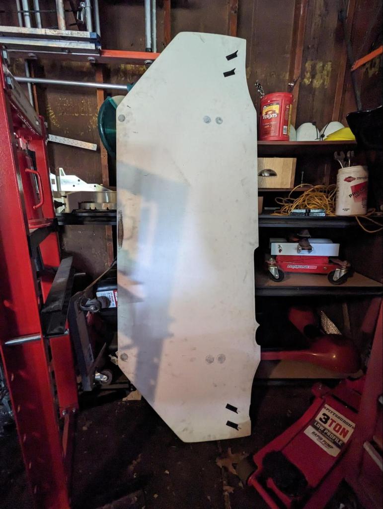
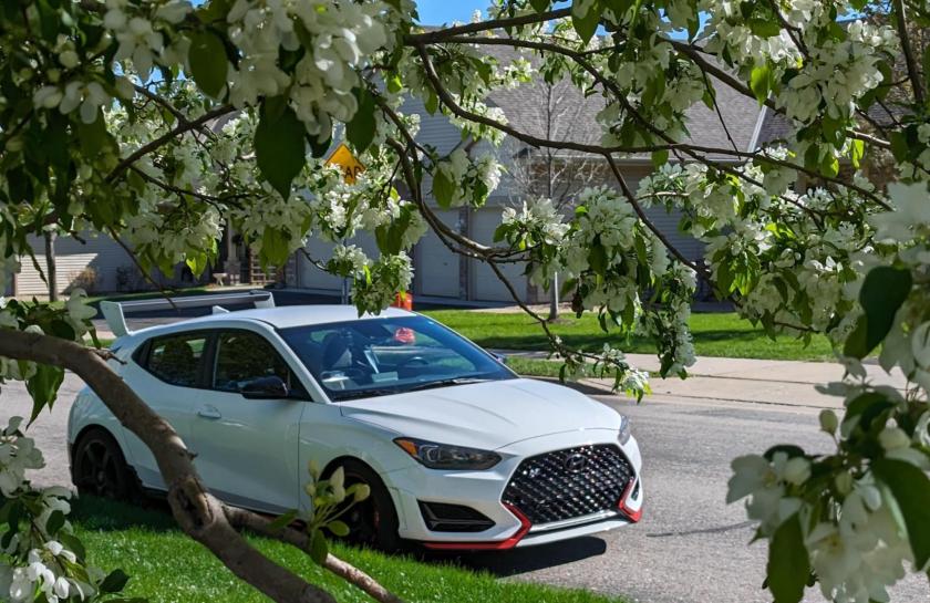
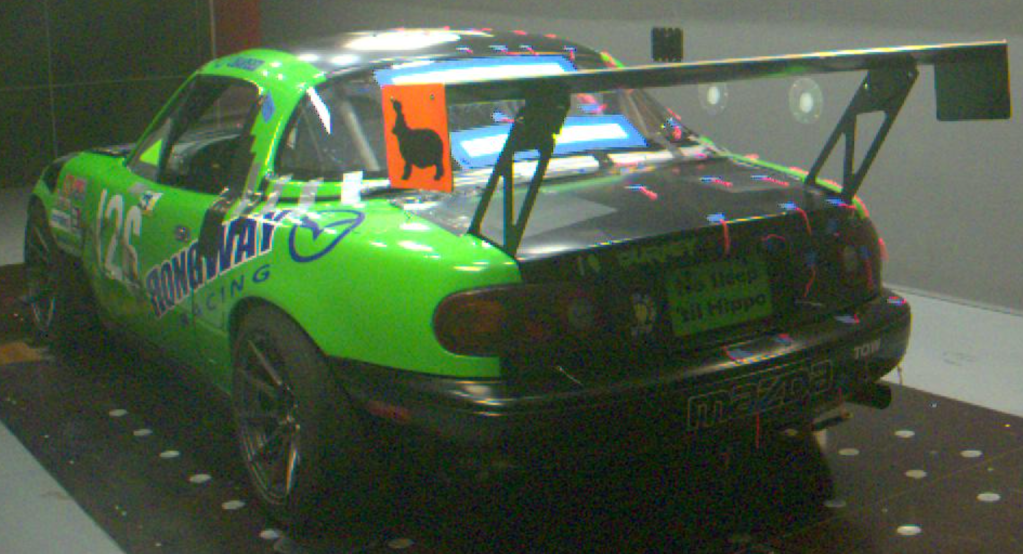
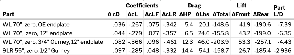
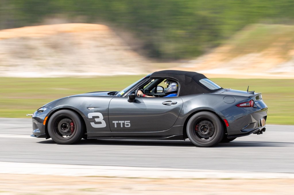
In early 2023, I finally broke down and purchased a Nine Lives Racing Big Wang kit. I also found a spare trunk lid on eBay to be the sacrificial new home for the 68-inch rear wing. The downside to this trunk-mounted wing setup is a lack of rigidity due to flimsy hinges, but in the spirit of a dual-purpose street car (and not wanting to permanently draw Fast and Furious style attention on the street), trunk lids with an extra pair of hinges can be swapped in a matter of seconds by undoing four 10mm nuts from the interior of the trunk.

.
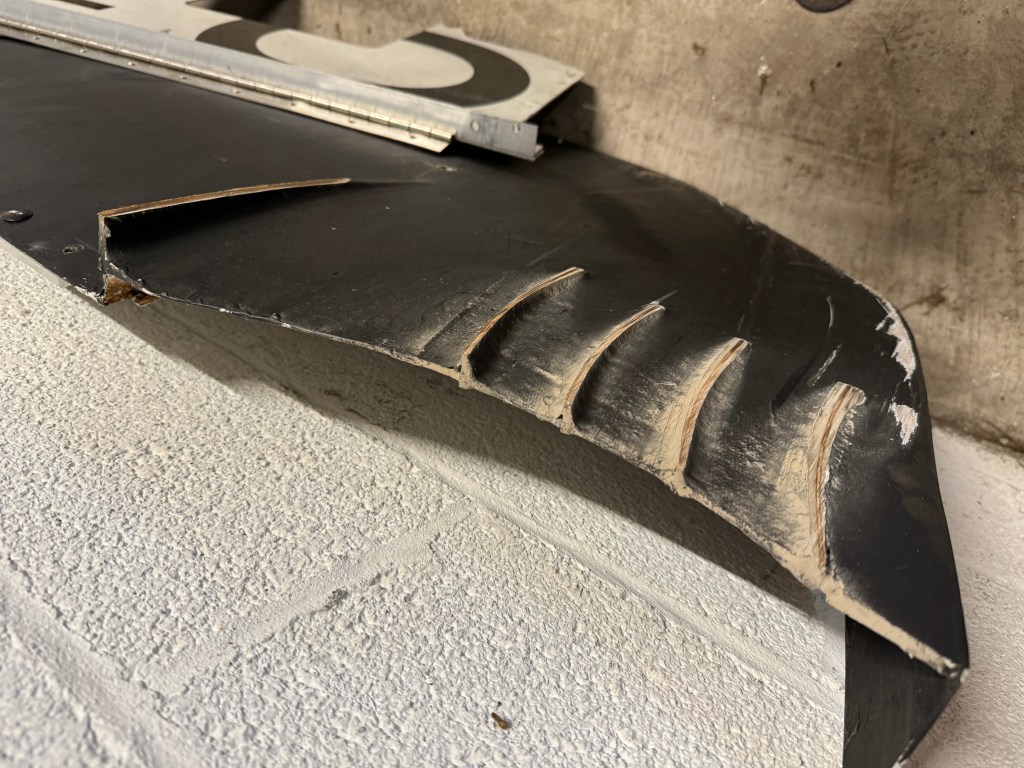
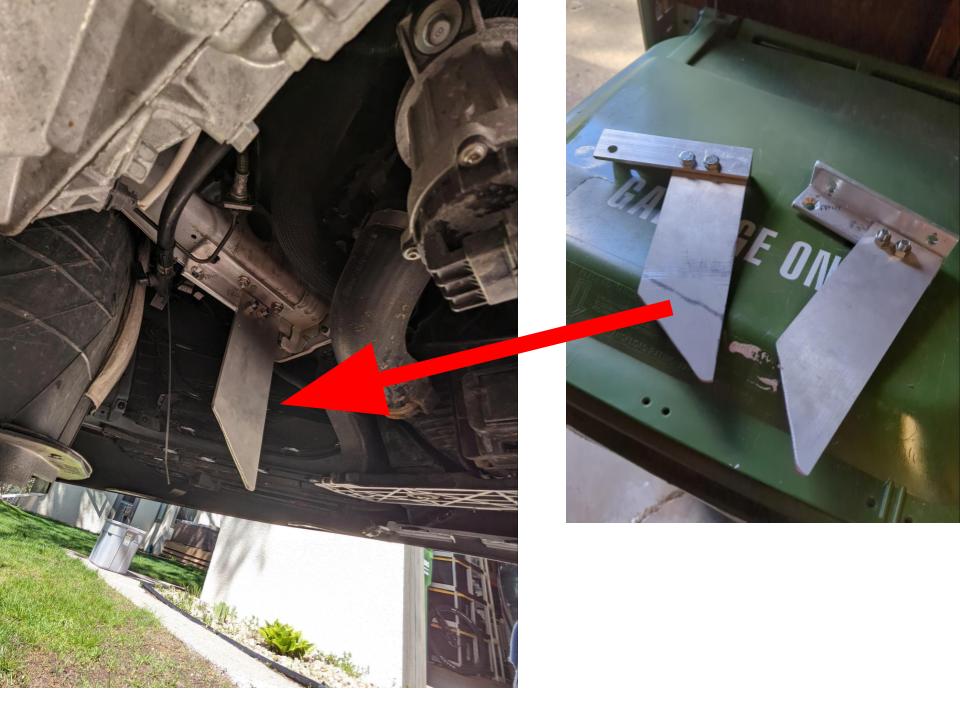
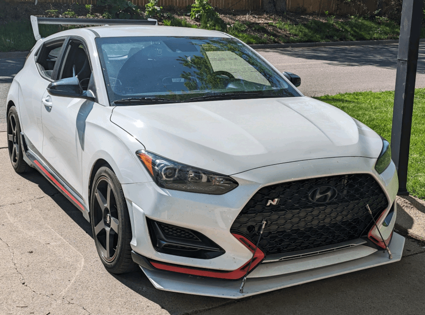
In order to balance out the new massive rear wing, I picked up a sheet of half-inch birch plywood from Home Depot and spent a weekend in the garage building a basic splitter. To be honest, this wasn’t something that I did a ton of research on before just diving in. I would have been content to buy a splitter kit designed to complement the rear wing, but there still isn’t much available in the aftermarket for ND splitters. Thanks to some helpful posts in the MX5 ND Track & HPDE Junkies Facebook group, homemade examples aren’t hard to find and duplicate. For ND owners who track, and aren’t afraid to rub through some fender liners, this is a fantastic community of like-minded members.
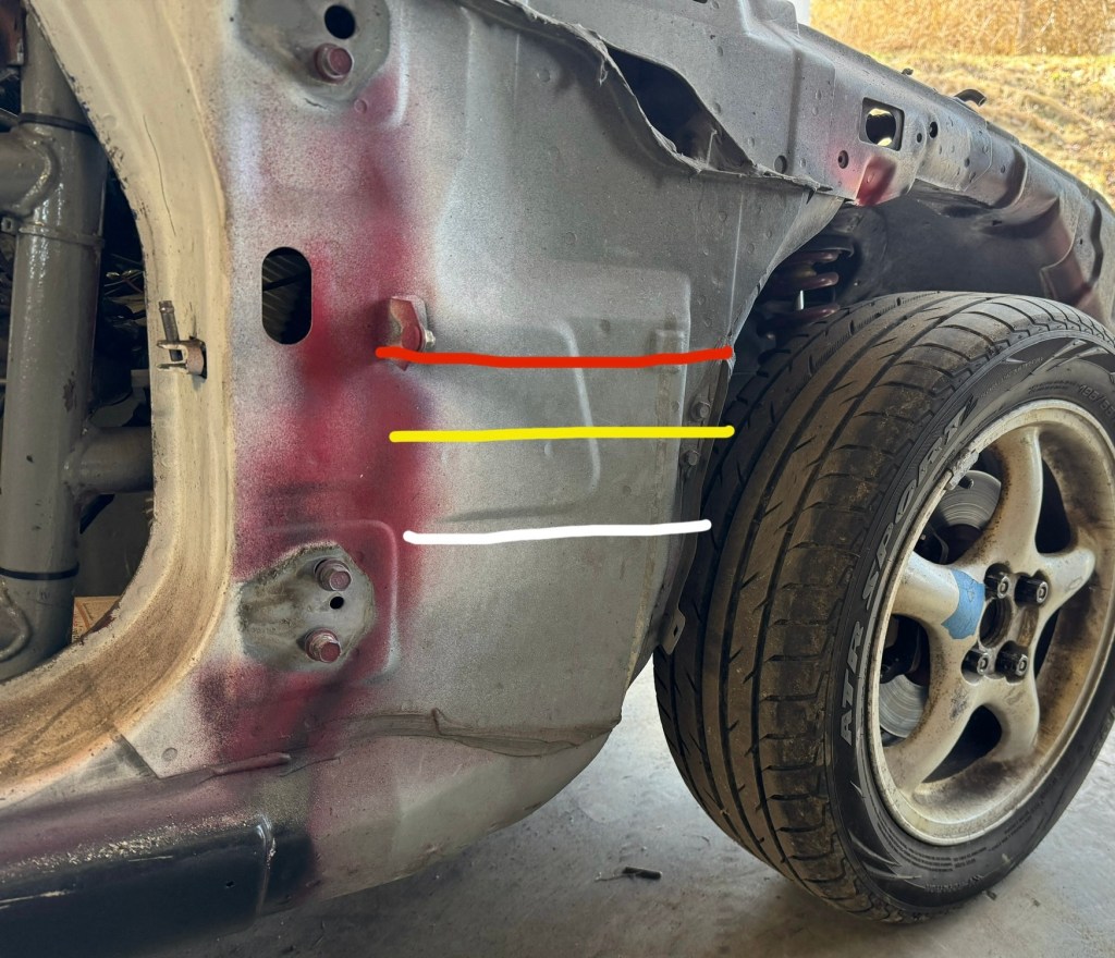
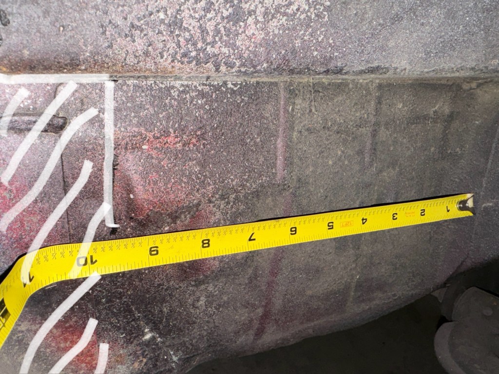
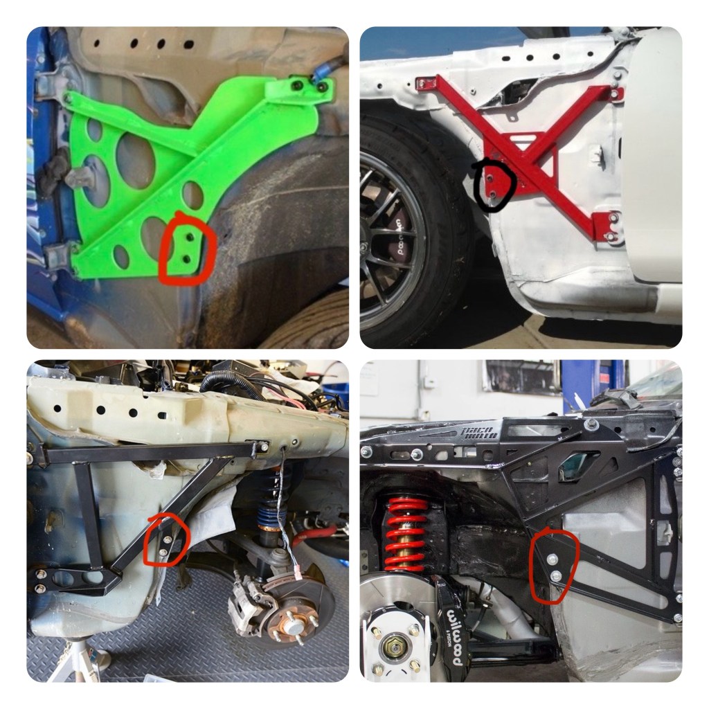
The chassis-mounted brackets were constructed with 1×1 inch angle aluminum – the height of which determines the splitter’s proximity to the ground. I targeted around four inches of generous ground clearance on stock-sized 17 inch wheels and tires, but this drops down half an inch when switched to my 15×9 setup.
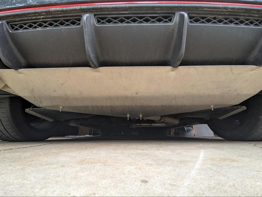
I gave the splitter blade roughly 3.5 inches of length beyond the bodywork and painted it with some cheap exterior latex paint. I used garden edging and a cardboard-traced strip of 1/8-inch HDPE from Speedway Motors to make an air dam – sealing the gap between the splitter and front bumper that now lacked the OEM Club lip. Overall, this DIY effort is still in the Occam’s Racer D+ grade range, but similar to the trunk lid, it can be quickly dropped with the removal of four bolts. It also helps that it was built for less than $150 in materials.
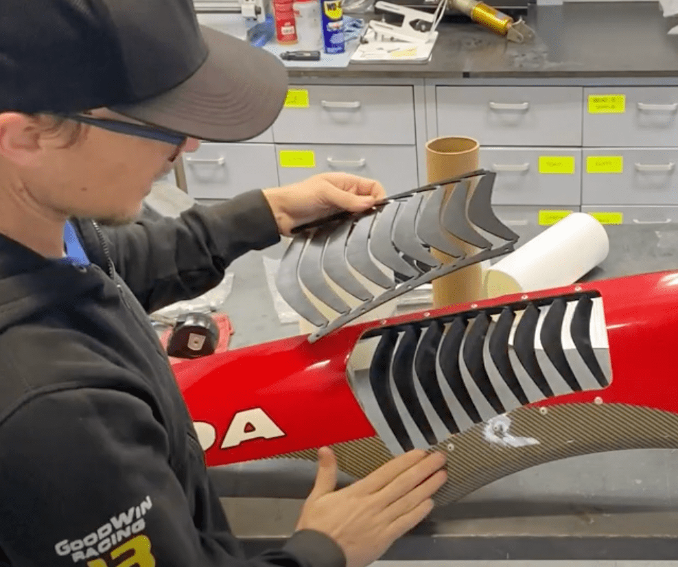
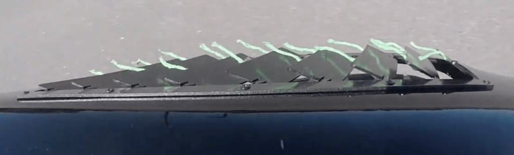
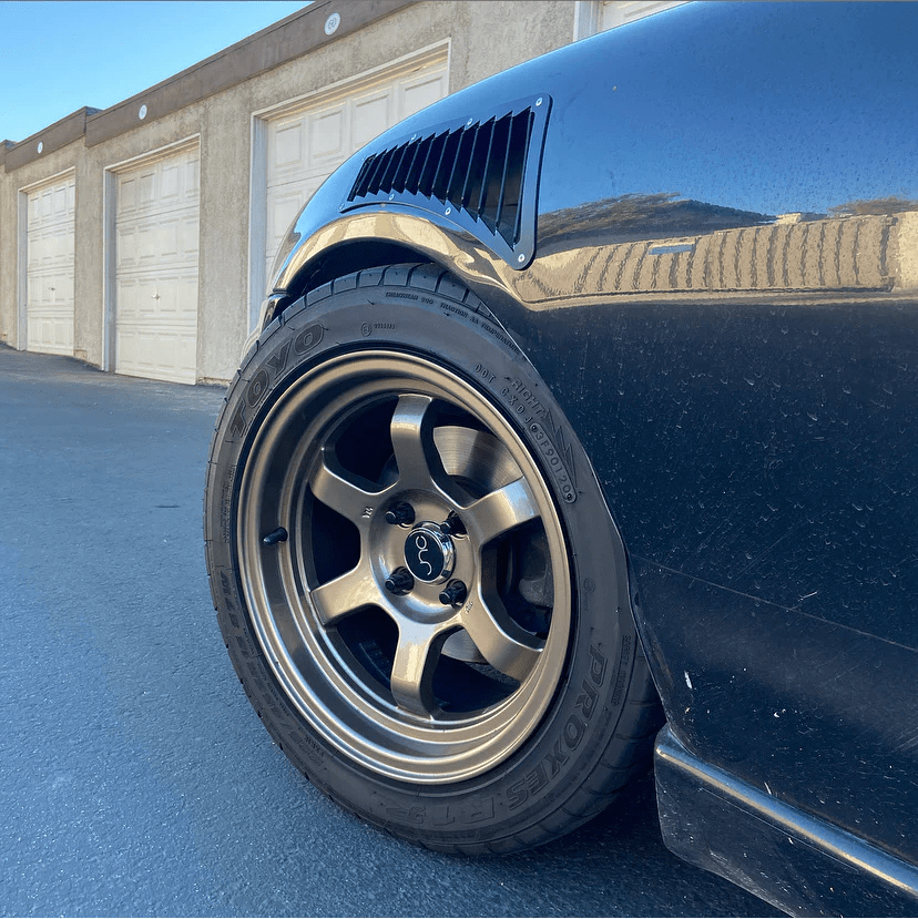
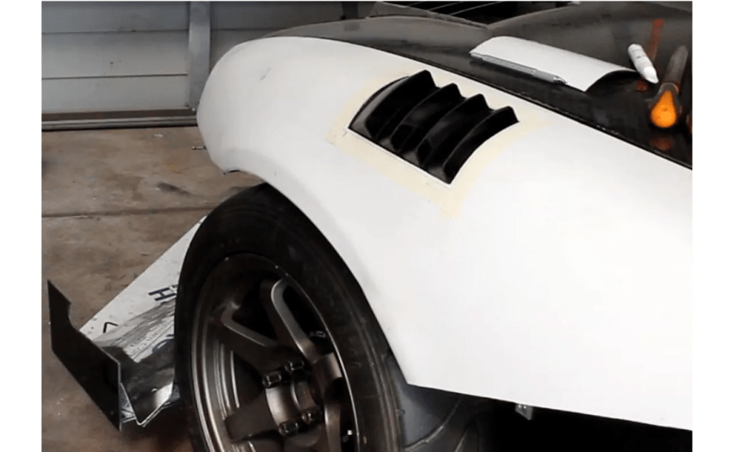
The 2023 Time Trial series season at the FIRM was still a struggle to try to get to the front of the pack, especially during the summer with a heat-intolerant tire like the A052. I played with rear wing AOA, stiffened rear suspension to leverage the dose of downforce, and even reluctantly cut some holes in the hood to further optimize my basic splitter.
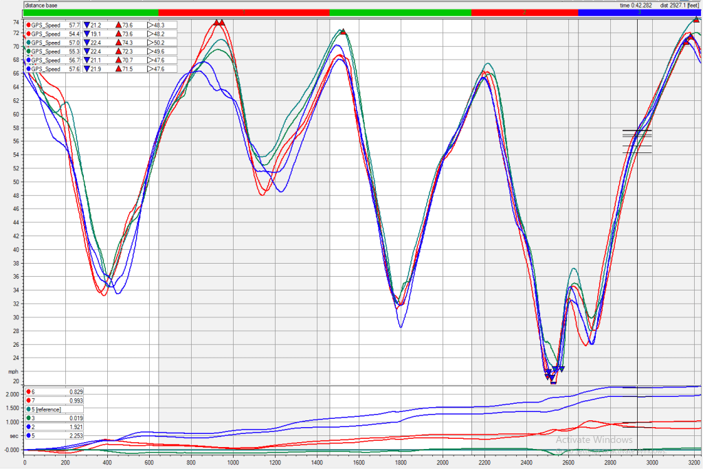
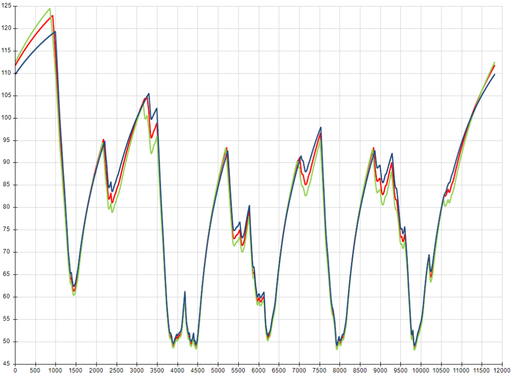
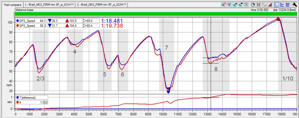
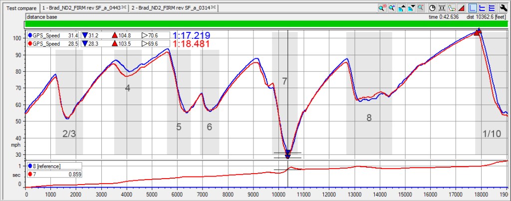
But after putting it off for so long, I’ve become a firm believer in aero. I initially noticed a slight drop in top end speed, but looking into the data, more than a second was found with the increased cornering speed.
I’m pretty pleased with the personal improvements made during the season, but the car still wasn’t fully optimized for the TT5 class, leaving some headroom for horsepower, and tire width. I ended up placing third in class overall without doing anything to the stock engine – mostly in an effort to preserve the allegedly fragile manual transmission.
But the FIRM demands horsepower. So for 2024, the car got a header, tune, and full exhaust. The updated dyno numbers didn’t show much in peak power, but looking at AIM data, there’s certainly a slight improvement to corner exit acceleration. I’m still running a 225 tire, but made the switch to a more forgiving RE-71RS.
The FIRM management made the wise decision to avoid scheduling events amidst the blazing summer temperatures in Florida. But once things cool off, there are still a couple more rounds of time trial competition remaining this fall. I believe I’m on target to run my first 1:16 on this combination of aero and a modest 10-15 hp bump over the stock engine. This was a lap that seemed impossible to me a couple of years ago – especially with what I still consider to be a casual approach to track driving, data coaching, and aerodynamic “development.”
To summarize my rudimentary introduction to aero: a little bit goes a long way. It’s certainly a slippery slope, but you don’t need to run some wind-tunnel-perfected setup on the first pass to see significant results. My Miata still has a basic, user-friendly aero-on-demand package.
Could it go faster with more expensive, race-focused improvements? Totally. Do I want it to become a car that loses streetability and lives on a lift or trailer? Absolutely not. Maybe this is an easy stance to take on a car that still has less than 30,000 miles on the odometer. Perhaps I can get away with drilling a few more holes while retaining a reasonable trade in value. But in the meantime, I’ll keep enjoying the best of both worlds.
| Thanks to Brad Alderman for this guest post, and proof that you can have your aero, and eat it, too. If you have an aero success story of your own, or car you want to brag about, see the details in Reader’s Rides. |