Pineview Run recently put out a new Track Safety Course in which they detail new rules for 2024, and show the official layouts. Many of the new layouts are a result of fast bypasses that short cut some of the more technical turns.
In very round figures, this is how the bypasses compare to the original course.
- Bypass 1: Going directly down the hill after Turn 2 is about 7 seconds faster than going through The Crick (turns 3-5).
- Bypass 2: Going around the outside of the uphill esses shaves off about 3 seconds per lap.
- Bypass 3: Short cutting the S-trap is worth about 6 seconds.
S1 = Shortest (Indy)
S1 is the shortest layout, and quite fast. This course was used for one of the races in the 2023 Pineview Challenge Cup. The biggest challenges are 1) drawing a straight line through the kink/bypass at T4, and 2) staying on the track at the exit of the knuckle.
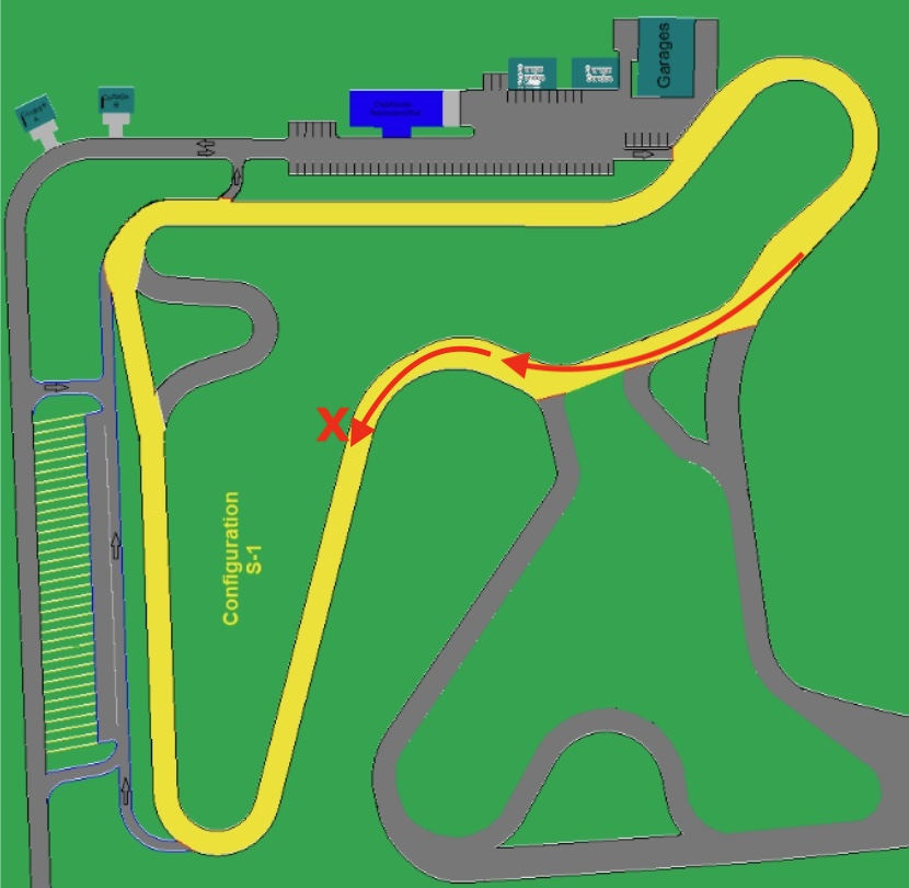
I call this one “Indy” because it’s like the shortest version of the Brands Hatch track, which they call Brands Hatch Indy. This is as small and simple as you can make Pineview, and would be good for winter driving clinics, where you don’t want to plow the whole track.
This track is about 40 seconds faster than the original course, and measures about 6/10ths of a mile on the driven line.
S2 = Short with S-trap (Kart)
Similar to S1, but including the S-trap. This has been the default layout for Wednesday and Thursday in 2024. It’s about 5/8 of a mile, and has a lap time around 34 seconds faster than the original layout.

S3 = Southern Loop
Either of the previous short layouts allows the S3 course to be run at the same time. The haripin is very tight, and braking for that, while maintaining speed for the steep uphill, will be an interesting challenge.

This layout was also used (with cones) for an autocross event in 2023, but I think the other short courses would be better for that. Also, I bet this layout could be run in the opposite direction, which might be more fun.
M1 = Triple Bypass (Gillette)
If you take the original track layout and add all three bypasses, you get a short and flowing circuit that’s heart-attack fast. Pineview calls it M1, but I call it “Gillette” in honor of Pineview Challenge Cup champion Jeremey Gillette, who beat everyone in 2022, and a triple bypass surgery in 2023.

If the first bypass is new to you, keep your wheels straight when going over the crest down the hill; the car gets very light here, and any amount of steering angle can bite you when the car settles down onto its suspension again. The bypasses combine to make this about 16 seconds faster than the original track.
M2 = Double Bypass
This track layout isn’t mentioned in the Pineview safety course, but they do run it occasionally. Note that the other layouts are called M1, M3, and M4, so perhaps they meant to include an M2 layout all along.
This course bypasses T4 and the S-trap, but keeps the uphill esses. Compared to the original layout, it’s a lot faster, but also removes the two most technical corners. This is a fun layout, just the same.

M3 = Happy Hour
I seem to recall this layout being used for Happy Hour, it uses only the first bypass. The S-trap is important for new drivers, as it slows cars down before entering the front straight. With only one bypass, this layout is about 7 seconds faster than the original.

A few years ago Pineview started hosting Ladies’ Night, which was for women only, and open to the public. The times they are a changing, and in 2024 it’s called Happy Hour, to be more inclusive of everyone, regardless of their gender or pronoun identification. On the flip side, the event is now for members only, and over double the price, making it far less inclusive. I don’t know what’s going on with that, but at least there’s still a ladies-only run group.
M4 = Original
This is the original track layout with no bypasses. It’s the most technical and busy course, and it might be my favorite. On the racing line, it’s almost exactly 1 mile long, with 15 turns and a lot of elevation crammed into that length.

I used to dislike the S-trap, especially on my motorcycle, but now after bypassing the S-trap, I like it both ways. On a motorcycle it’s a painfully slow corner (20 mph), but it was an easy place to catch people. Likewise for cars, if you get the S-trap right, you make up time on 99% of people. Most of that is people throwing away speed on the initial corner entry, but a lot of people also pinch the exit.
LCOF1 = Long Course
Pineview calls it LONG COURSE Open/Fast 1 (LCOF-1), but I would simply call it L1 or long course. This is the original track plus the extension, with all the bypasses. It’s fast, flowing, and fun, and hopefully what the big-car people wanted all along. (I was fine with the original track, but I’m a weirdo.)
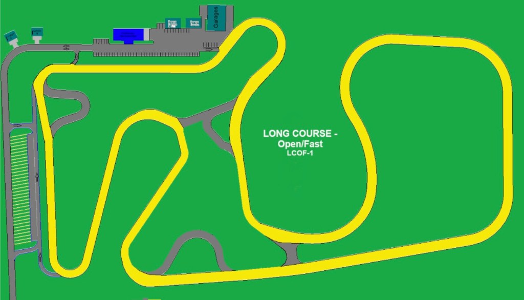
The new extension has more elevation than the old, and the new section of track is at least 10 feet wider. Fast cars will go over 100 mph on the back straight. The track measures just over 1.4 miles on the driven line.
LC3 = The Equalizer
This is the longest layout using all of the original circuit, plus the extension. I want to call it Marathon because of the length (1.5 miles), but I think of it as The Equalizer. On the original course, lighter and less powerful cars seemed to have an advantage with all the tight corners. However, the long course with the bypasses and extension gives the advantage back to heavier and more powerful cars. So when you combine all the technical corners from the original track with the fast and flowing nature of the extension, this should put all cars on equal footing. Hence, the Equalizer.
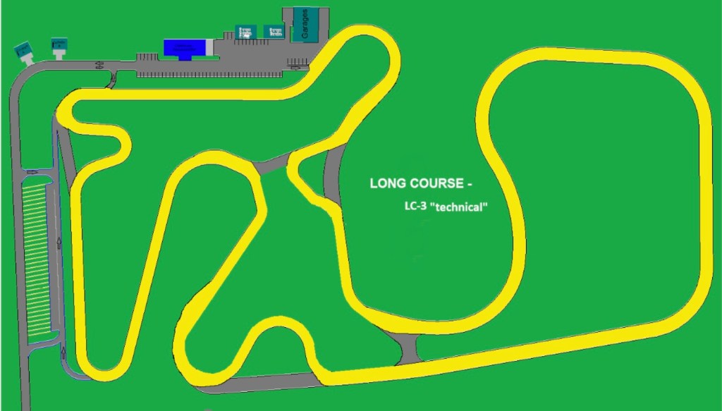
I’m really looking forward to this layout. I think the trickiest part will be transitioning from the extension’s back straight to the original course’s uphill esses. With so much speed going into a short 90-degree corner, it’ll be easy to blow the entry to T8. But if you do blow it, there’s a lot of runoff going up the hill if you miss your braking marker.
Missing layouts?
That’s 9 track layouts, but if you do the math, there are a 16 track configurations possible. So what’s missing from the “official” track list?
- OG no S-Trap – Several members have complained for years about the S-trap being too slow. An easy solution is to use the original course, but bypass the S-trap. But that configuration doesn’t exist in the official documentation.
- Long course + crick – Turn 4 is the most technical corner at Pineview, and I’d like to see it added to the long course. The crick, as I call it, also slows cars going down the hill, and makes it much less likely for there to be a “coming together” on the back straight.
- Long course + esses – The uphill esses are painfully slow in a FWD car, and I can see why some people might want to avoid them. But braking from high speed on the back straight and then having to turn into T8 and go up the esses would be very challenging. People will get to do this in the LC3 layout (Equalizer), so it’s not a high priority to add this option separately.
- Long course + S-trap – This is missing from the list, but not one I’d be interested in.
- Double Combinations – And then there are three long course combinations that use two bypasses instead of one or all three. Of those, the only one that’s compelling are adding both the crick and the esses. But this is so close to L3, so why bother.
Drive it!
That wraps up the possible layouts at Pineview, at least going in a clockwise direction. However, as of this writing, only the original layout options are open. There’s still some work being done on the extension, and we expect to drive on the long courses starting in June.
I’ve driven on the repaved extension, and it’s good. I had previously complained about bumps on the new asphalt, and the dip going up the back straight, but all of these have been addressed. There are a couple patches where the asphalt isn’t perfect, and a couple undulations on the extension that could be smoothed out more. Once the circuit gets a final coat of asphalt, I feel this track will rival any track on the east coast.
If you want to try out the track, Pineview is open Wednesday to Sunday. You can get a guest pass here. Or check the calendar for events when S2K Takeover, Mass Tuning, SCDA, and Xtreme Xperience have rented the track. Those groups bring their own insurance, and it might be easier to get on track with them (no track safety class, no Raceiver radio requirement, etc). If you are a regular follower of my blog, definitely contact me before you come to Pineview, there’s a good chance I can meet you there.
Note that one of the new rules for 2024 is a sound ordinance by the town of Otisco. The law states a limit of 70 db at the property line, which is 250′ in this case. That means your vehicle must measure 88 db at 30′ or 92 db at 20′, with your engine at 3500 rpm. If you think the residents of Otisco have it out for Pineview, they absolutely do (and PV now joins other tracks with this problem, like Laguna Seca, Lime Rock, Waterford, etc).
Pineview’s neighbor to the south is Wonderland Forest, an outdoor concert venue for hippy bands, and they also have the residents up in arms over their music festivals. Wonderland is going to court with the town of Otisco over the sound issue, so thanks to them for doing the heavy lifting. Let’s see how this one plays out, until then, please muffle your exhausts.