If I was to grade the average splitter I see on the average track car, I’d give it a D+. I know that grades are supposed to average out to a C, but the average person sucks at aero. I see better splitters on Miatas than other cars, and those generally fall in the C+ range.
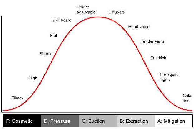
- Grade F: Flimsy splitters or front lips, usually bought on Amazon or eBay, but some reputable aero companies also produce shit. These look like splitters, but that’s where the similarity ends.
- Grade D: A misunderstanding of how splitters work results in splitters that are optimized for the top surface, not the bottom. They are are often too high or too low, and universally have sharp leading edges and are flat. Most have splitters wider than the front fascia, but do nothing with the exposed ends. Some might have a spill board on the outer edge, which is at least something, but that does nothing for the underside.
- Grade C: A splitter gains downforce through suction, which is achieved primarily through proximity to the ground and using diffusers and/or curvature to accelerate the air underneath. A splitter without height adjustment is like a wing without angle adjustment. A splitter without any diffusion is as useless as a flat wing.
- Grade B: With great suction comes great responsibility. Because the air under the splitter is low pressure, everything around it is higher pressure and wants to get in there. You need to extract air using hood vents and fender vents, and kick air upwards and outwards wherever possible.
- Grade A: At this point the splitter is making a lot of downforce, but there are still minor problems that occur around the wheels. Air hitting the rotating tires compresses and squirts out under the splitter, and air intrudes through the wheel spokes as well. Mitigating losses around the wheels and tires is the last frontier.
Grade A
Let me show you what a solid Grade-A splitter looks like. It’s not surprising that it’s on a Miata, because we do aero better. We have to; our cars suck. It’s also not surprising my teammate Alyssa Merrill made this. We bounce ideas back and forth, and while I think I’m pretty clever, she’s got a lot of great ideas of her own.
First, you have to use the right material. Alumalite is an automatic grade C, not because of the material properties, but every single person using Alumalite leaves a sharp leading edge. Despite the fact that Alumalite curves nicely, pretty much all of them are flat, as well.
Alyssa chose to use my favorite splitter material, Meranti BS6566 plywood. It’s very light (32 lbs/cu-ft), stiff, easy to work with, boil tested for delamination, and x-rayed for voids. It’s expensive, but you get what you pay for. She’s doubled the thickness of the lip to about an inch and done a good job of rounding the underside of the leading edge, so that air stays attached along the bottom surface.

The location of the radiator opening makes a difference to how the pressure side of the splitter functions, and has an effect on drag and cooling. I’ve seen a lot of radiator openings just barely off the splitter. When you put a hole there (for radiator or brake ducts), you lose the high pressure air bubble on top of the splitter, and with it, some of the downforce you’re trying to make. You might be thinking that a lower opening is better for cooling, but with the radiator opening down low, the air has to take a hard upward turn inside your radiator duct. Air can’t change directions at more than 12 degrees, and because the duct is much steeper than that, air separates from the surface of the duct causing drag and losing cooling efficiency.
Alyssa made the radiator opening as high as is practical while retaining the center bumper support. The higher opening holds a larger/taller high-pressure air bubble on top of the splitter, making more downforce. In addition, this provides a straighter route to the radiator, increasing cooling efficiency and decreasing drag.

All the air that goes through the radiator has to go someplace, and the worst place for that is under the car. The best place to send that air is upwards, because it creates downforce. Some people will use louvered hood vents, while others will use just a front wicker and a gaping hole behind. Louvers smooth the air over the hood, and result in less downstream losses on the wing. But since most cars are front-limited with respect to downforce, a gaping hole is a better solution for a track-only car. For a street car, louvers look better for sure.
Having a splitter without any height adjustment is akin to a rear wing without any angle adjustment. You see that kind of junk on OEM body kits, and you can do better. With a proper wing, tuning the high-speed handling of your car is as simple as changing wing angle.
It’s like that with splitters as well. Most of the downforce comes via interaction with the ground, so setting the height is critical. I’ve seen a lot of splitters that adjust for height initially, but then once you mount the airdam or fascia, the height is fixed. This is a C grade. At least there was some height adjustment at first, and that’s an acceptable situation if you can later modify it.
People getting a B grade with a fixed height splitter do so because they understand aero maps and have set their splitter height for maximum downforce, and thereafter do all of their adjustments via wing angle. But having both ends adjustable for downforce is obviously even better.
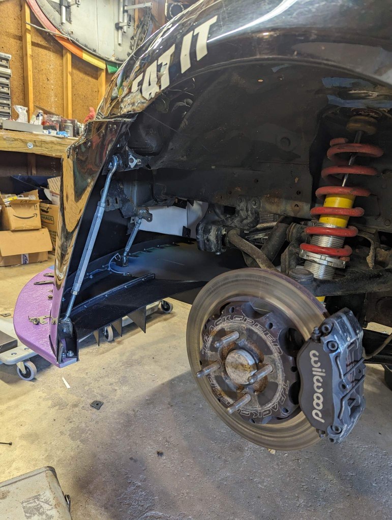
A-grade splitters are adjustable after the fact. Alyssa used turnbuckles to support the splitter, which are sturdy and make height adjustment a simple twist of the wrist. The turnbuckles are behind the airdam, which makes height adjustment more difficult, but it also completely hides them, for less drag. This is some trick shit.
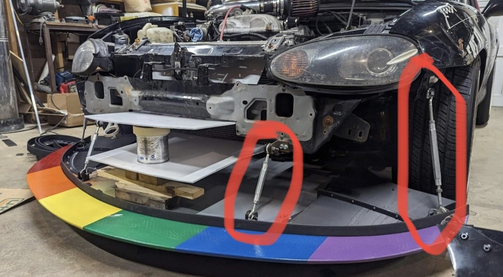
What’s even more trick is that the turnbuckles fasten with pins, and so removing the splitter entirely is super easy. Just yank four pins and the splitter drops off the front.

Another area to address is the width of the splitter, and what to do with the ends. Under most racing/TT rules, splitters can be the width of the car or the front tires. In most cases, this results in some unused material on the outside edge of the splitter.
You get a D for doing nothing with the exposed end. A flat splitter with a flat exposed end is just additional drag and an invitation to catch on something. You get a C for putting a spill board on the outside, because while this can reduce drag, there are so many better uses of that real estate. Higher grades are achieved by putting a vertical dam on the outside edge (front tire spat if you will), which builds local pressure on top of the blade, creating more downforce. Also, air spilling off that will direct air sideways, extracting air beneath the splitter, making more downforce.
Alyssa chose to do something similar, but pulled the bottom edge of the airdam outwards to meet the end of the splitter. This won’t make quite as much local pressure on top, but should be better at sideways extraction and have less drag. Hard to say which is better, both work.
Let me address another huge mistake: flat splitters. Most people understand wings, and and flat splitters are like flat wings; meaningless. You need some curvature in the rear of the splitter to diffuse the air. When air expands behind a restriction, it accelerates the air in front of it, lowering the pressure. This suction is the purpose of a splitter.
Time attack cars often curve the entire rear of splitter blade upwards, essentially making a splitter diffuser the full width of the car. Miatas have historically used the rear subframe as mounting points for the back of the splitter, and the consequence of that is that Miata splitters are flat. To get suction, Miatas need to use splitter diffusers.
Splitter diffusers operate on the same principle as rear diffusers; they expand air in the tunnel. The diffuser itself doesn’t create the downforce, but it helps air expand and creates downforce in front of it.
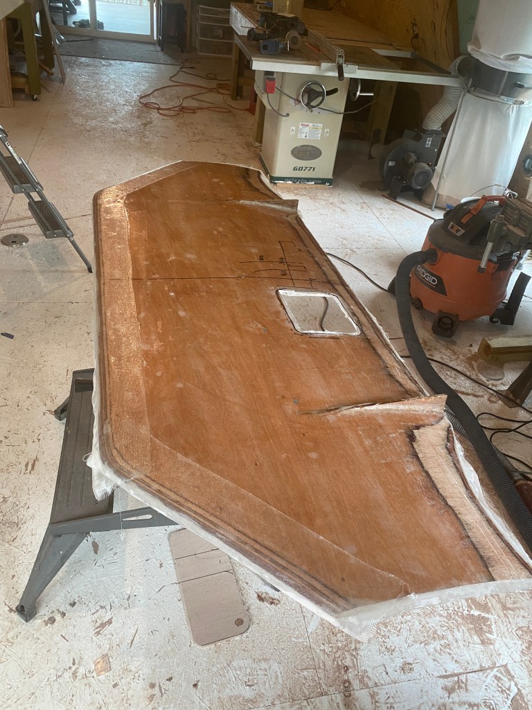
Alyssa and I are designing splitter diffusers and will make them for sale sometime this summer. Here’s your first sneak peak.

These splitter diffusers have one large tunnel that diffuses air inboard of the wheels. This is an area of loss to begin with, and also an easy place to extract air from. Most splitters diffusers have only the one main tunnel.
But you’ll notice our splitter diffuser has additional area outside the main diffuser, with strakes. The purpose of this area is to mitigate tire squirt. As a tire rolls forward, it compresses the high-velocity air underneath it, squirting air out the sides. Some of this air goes under the splitter, which decreases the suction and downforce. By adding a diffuser in this area, it slows the air down, hitting the tires with less velocity.
The strakes spin a vortex off the trailing edge. Because vortexes take energy to create, the air hitting the tire has less energy, which reduces the amount of tire squirt. The strakes are also angled just-so, to achieve the maximum amount of extraction from under the splitter and send it outboard, protecting the main tunnel of the splitter diffuser.
Recall that most of the air is dumped inside the wheel well. Air here is extracted via vents on top of the fender, and behind the wheel. By extracting air upwards, you create an opposing force downwards. And by sending air sideways, you mitigate losses from air intruding underneath. Fender vents are important to make the most out of splitter diffusers.
A+ splitter
There’s an old saying I think attributed to fighter aircraft: 90% of the cost is the last 10% of performance. The same applies to car aerodynamics. While this splitter is a solid A, to make this into an A+ requires a lot of labor and cost, for little return.
First, I’d cut out the center bumper support completely, it isn’t necessary for chassis rigidity, and I can fashion a custom bumper after ducting the radiator. Removing that center support allows a slightly higher radiator intake, with the benefits I already discussed. I’d put a 100mm radius on the edge of the radiator duct, and reduce the opening size slightly.
I’d also tilt the radiator forward to reduce the frontal area, and duct the radiator exit straight upwards through an extractor vent to create more downforce. You might call this more engine bay management than splitter improvement, but it’s all related to creating more front downforce, and goes hand-in-hand with designing the splitter and ducting.
I’d also make the splitter slightly wider. Alyssa’s car is for HPDEs and is unbound by racing rules, so an extra couple inches on the end isn’t a problem. With that extra space I’d place place a simple piece of angle aluminum. This end-wicker, if you will, holds pressure on top of the blade and locates a higher stagnation point behind. This pressure differential creates more downforce, and it’ll still kick air sideways for extraction.
With a clean sheet, I’d also add curvature to the entire undertray. I’d laminate two pieces of 6mm plywood together, rather than using a single piece of 12mm. This would allow the rear edge to sweep upwards, creating more suction under the middle of the splitter blade.
Alyssa’s car doesn’t have a flat bottom, so it’s not a huge problem to diffuse some air into the center of the car. There will be some additional downstream drag due to local flow separations around the suspension bits, exhaust, transmission etc, but this is just a little bit of extra drag on things that were already creating drag to begin with.
I’d also put some height differential between the center and sides of the splitter. Remember early last year when all the F1 cars were porpoising? That was a cyclic gain and loss of downforce via ground effect, and it’s the natural consequence of trying to make as much downforce as possible, losing that downforce, and watching the car rebound on its springs. Once the car is back at a taller ride height, it again gains more downforce, repeating the cycle.
Many cars mitigate that effect by having a higher center tunnel, which gives two different heights of the splitter. This way if the lower part of the splitter goes under 1.5″ height, you don’t suddenly lose all of the downforce. The higher center portion also feeds the underside aero, which isn’t a factor on Alyssa’s car, which has neither a center tunnel nor a flat bottom.
So on her car I’d make the sides of the splitter slightly higher, rather than the middle. This will have the same effect of balancing ground effect losses, and will also protect the splitter blade, because the sides will ground out before the middle when cornering.
Finally, I might address some of the aerodynamic losses that come through the wheel spokes. By covering the bottom half of the wheel with caketin covers and spinning a vortex outboard, I’d reduce losses and redirect air down and out, with a minor gain in splitter suction.
But like I started with, modifying her splitter to go from A to A+ is a 90% effort for 10% gain situation. Addressing other parts of the car to the 90% threshold is time better spent.

Hi, sorry to resurrect this, wondering if you know where Alyssa got the deck mount hinges she’s used for her quick release points? I’m building a similar splitter, don’t want to shell out a few hundred for a sturdy bois-type mount and turnbuckles seem like the best option.
LikeLike
Probably McMaster, but ask her (find her on Facebook)
LikeLike