Wing Logic Dual Element

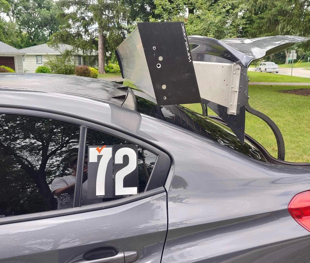
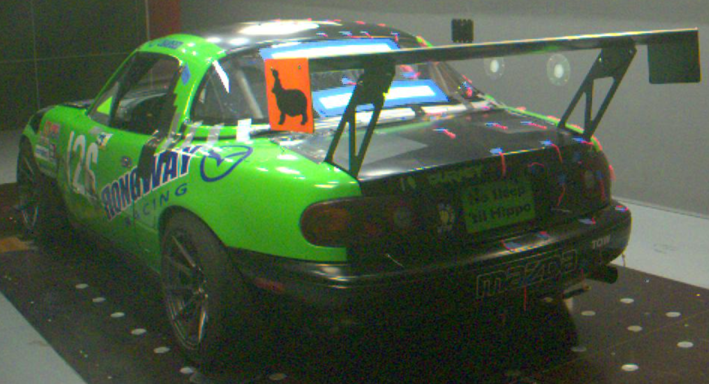
In the previous article, I mounted a Wing Logic wing to Steve Leo’s WRX. He’s been pretty happy with it, but I’ve been wondering about adding more rear downforce. An excess of rear downforce can make a car boring to drive, but it also improves braking, high-speed stability, and requires fewer corrections when you lose control. So while more rear downforce might ruin the aerodynamic balance, if the driver goes 2 seconds faster, let’s call that a better car.

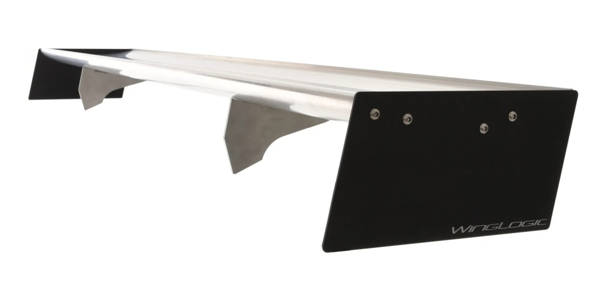
If you want more downforce from a Wing Logic wing, you can increase the size of the Gurney flap by duct-taping down a piece of angle aluminum butted up against the built-in 1/4” Gurney flap. And with the larger wicker, you can add a little more wing angle. But you’ll soon hit a point of diminishing returns, and shortly after that, the wing will stall out. I haven’t run a full sweep on this wing, but I’ll guesstimate that a Gurney flap 1″ tall (very draggy) and an angle of attack around 11-12 degrees is the limit.

If you still need more downforce, the easiest way to do that is add a second element above the main wing, set somewhere between 25-35 degrees angle of attack (in relation to the main wing). Unlike the single wing, the double wing won’t stall because of the slot between the wings; Air shoots through the gap at great speed and this keeps air attached to the underside of the upper wing. Thus you can run more angle on the upper wing, which effectively increases both the chord and camber of the entire wing, without flow separation.

If you have a 9 Lives Racing wing, they can sell you a dual element wing for around $440 (with shipping). The kit includes the upper wing, plus adjustment brackets that go inside the standard end plate, plus little brackets that go in the Gurney flap slot. It’s a clever arrangement that’s easy to install and remove. I tested the double wing in a wind tunnel, and came away really impressed with how well it worked.

If you have a Wing Logic wing and you want a dual element, you’re shit out of luck. There isn’t a similar kit available, and I have yet to see anyone cobble something together. I wonder if the reason for that is because some people believe (incorrectly) that you can’t put a dual-element wing on top of a wing that has a Gurney flap? There was a recent discussion of this on the Professional Awesome Facebook group, and it seemed like most of the people said you should cut off the Gurney flap, or a dual wing won’t work with a Gurney flap on the lower wing, or that Gurney flaps only work on the top wing. That’s horseshit.

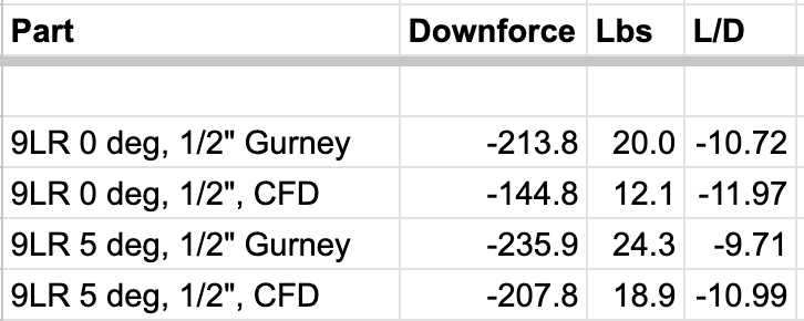
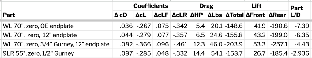
You can absolutely put a Gurney flap on the lower wing. Two research papers (James C Moss , and later F.M. Catalano and G. L. Brand) concluded that adding a Gurney flap to the main (bottom) element of a dual-element wing added downforce and improved L/D ratio. By fiddling with the Gurney flap height, overlap, and gap, they increased lift by 12% and increased L/D ratio by 40%.

But before you go adding a Gurney flap to your double wing, you should know that the authors only got those results after tons of experimentation. The height of the Gurney flap, the distance (gap) between the wings, and the overlap between the wings all need to be set correctly to get the most out of it. Knowing all of this, if you’re going to put an upper element on a Wing Logic wing (or any wing with a Gurney flap), you’ll need to be able to adjust the upper wing’s X-Y-Z coordinates for angle, gap, and overlap.

If this is all too much work for you, go and buy a 9 Lives Racing Big Wang and add The Deuce double element kit. It’s already set up with the right overlap and gap, and is simple to adjust for angle. The performance is excellent, and you will not be disappointed. Tell Johnny I said hi.

But if you’re a DIY-or-die kind of person (ahem, guilty), or you have more time than money, then maybe putting together your own dual wing how you want to spend a day. If that’s the case, read on and I’ll walk you through how I made a dual element for a Wing Logic.

Assembling the upper wing

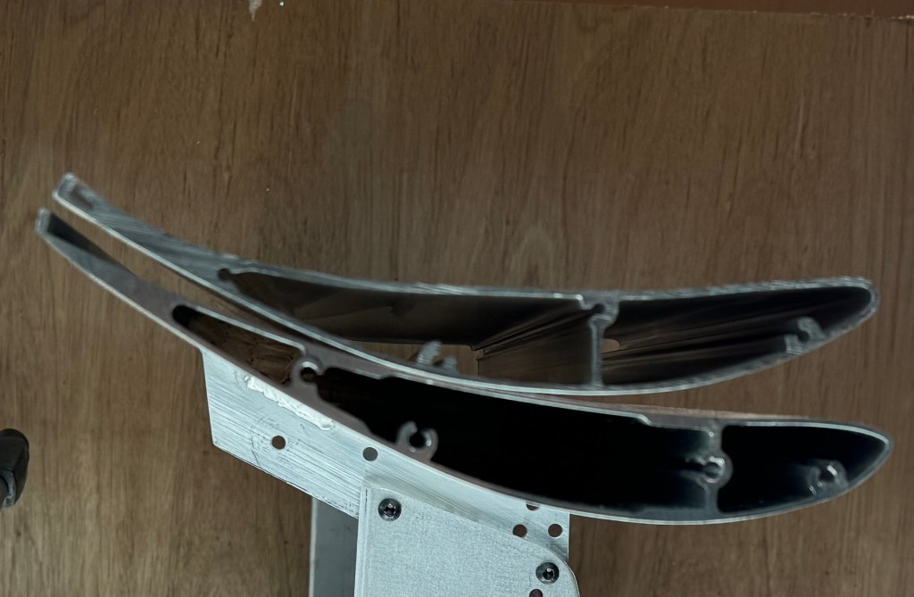
I make wings rather than buy them, mostly so that I can experiment with different shaped airfoils and construction methods. My S1223 is a torsion box, and my MSHD is a foam core with fiberglass. But neither of those construction methods works great for a wing with a much smaller chord and less thickness. So rather than build one from scratch, I bought a couple cheap extruded aluminum wings on Amazon for $35 each. You can sometimes find them cheaper, and my friend Bill Fischer of Garage Heroes in Training once bought one of these wings and got a box of 10 for the same price.

Cheap extruded wing from Amazon, eBay, etc.

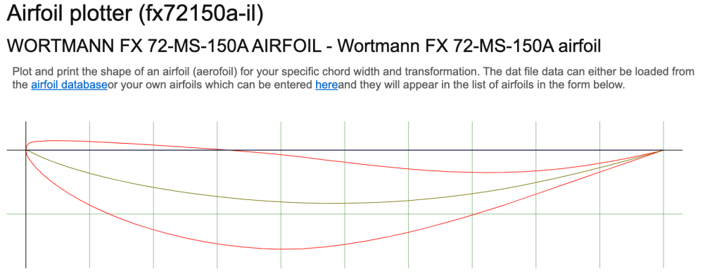
I’m not exactly sure what the airfoil is, but it looks a bit like a Wortmann FX 72-MS-150A. With a cL of 1.8, this is decent, but not what I’d call an ultra-high lift wing. According to my Car Wing Comparisons article, the airfoil outperforms the NASCAR used for in their Car of Tomorrow for a hot second.

Airfoil Tools is a great place to research wings.

These cheap extruded aluminum wings are strong and light. They have two internal semi-circular spars that run the length of the wing, and provide a lot of stiffness. These supports are also tapped with M8 threads and do double duty fastening the end plates. While I might wish for a different shaped airfoil, the entire design is lightweight, sturdy, and inexpensive.

The wing has a 4.7” chord, which is larger than the upper element 9 Lives Racing uses. A rule of thumb is that the upper element should be about 30-40% the chord of the total wing (combined chord of main and second element), and this second element comes in at 32% of the combined 14.7”, and that’s right in the ballpark.

Wing profile and center support.

The longest of these cheapo wings I’ve found is 135cm (53.3”), and so if you want a bigger wing than that, you’re going to have to figure out a way to join them together. Welding is the obvious solution, but I didn’t want to rely on skin strength alone, I wanted to add an internal support as well.

M8 stud is threaded into both sides.

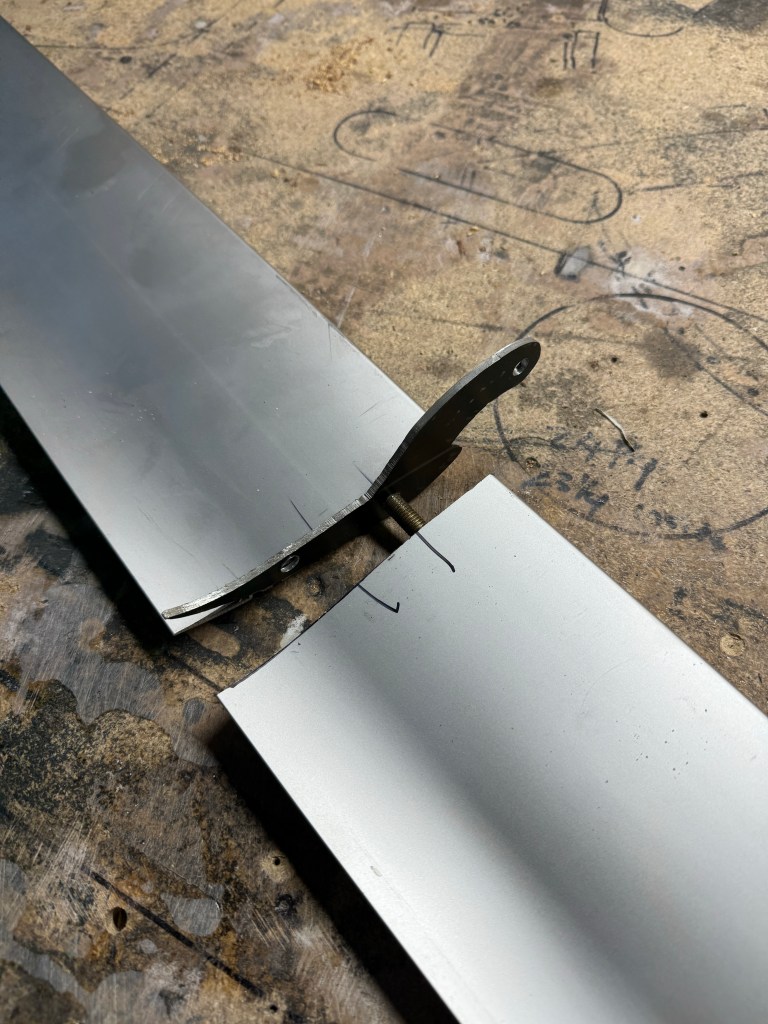
I cut threads into one of the wing holes and installed a M8 stud, bottoming it out on the threads. Then I tapped the same hole on the other wing. I sandwiched a little bracket between them, which will be used to hold up the center of the wing, and then twisted them upon each other, essentially threading the two wings together.

Both halves threaded together.

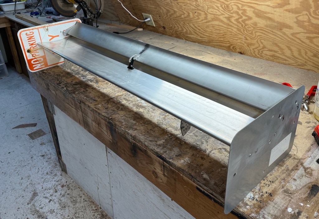
I took the wing to a local fabrication shop and they charged me their hourly minimum of $80 to weld it up. So that’s $150 for the upper wing, all in. I’m sure the welding could be done cheaper, especially if I was doing several wings at the same time.

Welded all the way around, and pivoting on the center support.

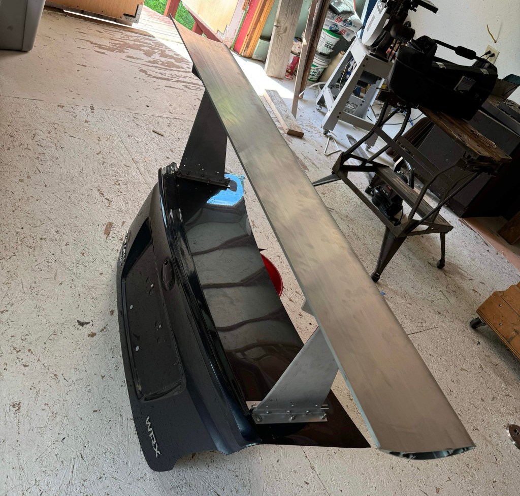
Double wing end plates

To mount the upper wing to the lower, I’d need to make new larger end plates that hold the ends of the upper wing. The top wing also needs to be able to adjust for angle, gap, and overlap, and because it fits inside the end plate, it’s kind of an end plate within an end plate situation. I made the inner plates from 9mm plywood because I needed to countersink the 8mm hardware into the ends. If I used 12 gauge aluminum, the bolt heads would stick up proud and keep the wing from changing angle.

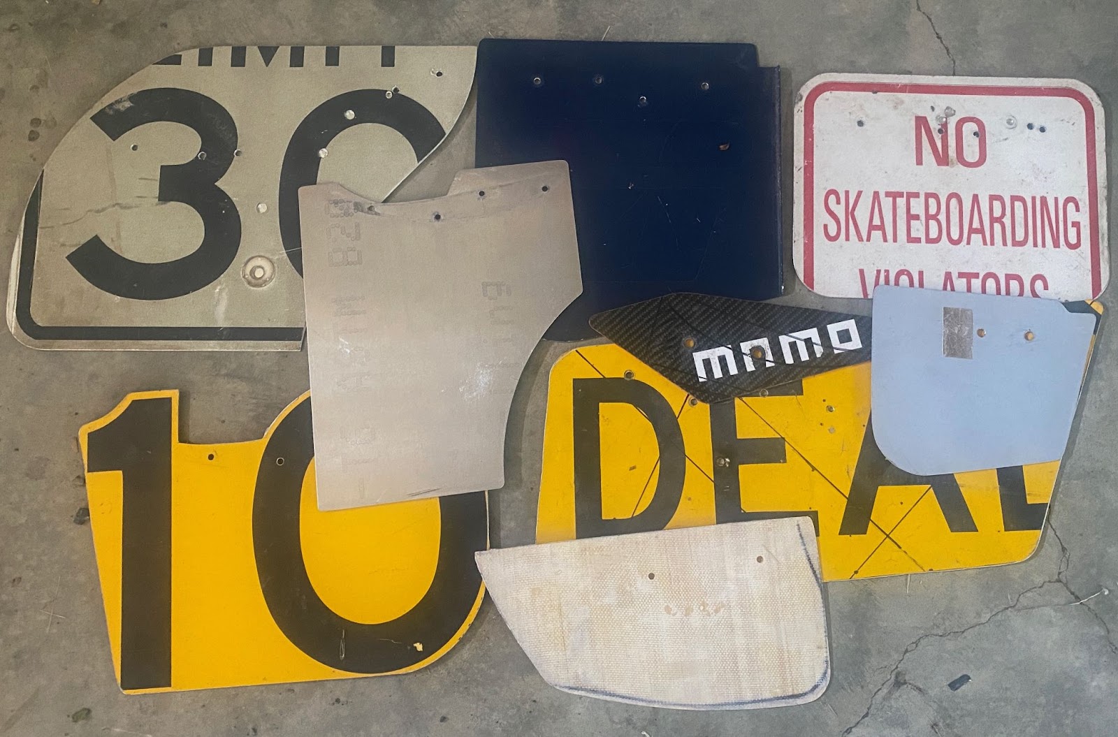
Maximum angle for a second element is typically around 40 degrees, measured from the bottom element. But at this angle, the upper wing risks flow separation. A safer bet is to set the upper wing to 35 degrees, which should provide nearly the same downforce as the maximum angle of attack. I traced all this out on the end plate (a No Parking street sign, per my usual $1-per-pound source at the metal recycler).

I always lay out the chord line parallel to the upper edge of the end plate, this makes it easy to set the angle of the wing. I’m also mocking up the position of the upper wing.

I first made the maximum downforce 35-degree setting, and to this I added a low-drag setting of 25 degrees. I don’t see needing any more adjustment than that, because I can always rake the entire wing to adjust between the high- and low-downforce settings. If I want less downforce, I’ll just remove the upper wing and run it as a single. From there I can tune wing angle and Gurney flap height as I would any other single element wing.

Upper wing pivots inside of end plate. You can see the forward hole, which increases overlap and gap. The gaps are larger than you’d have normally, because of the Gurney flap.

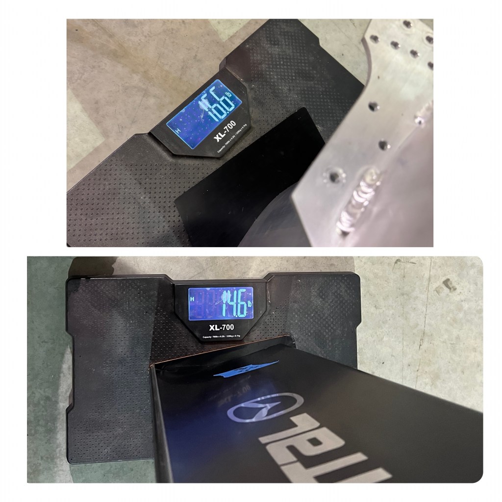
The completed double wing weighs 22.8 lbs total, and so the upper wing added only 6.2 lbs, including all of the things required to mount it. That’s pretty light, and it feels quite sturdy. Eventually I’ll lighten the main wing by milling out slots and wrapping it with carbon fiber. But more on that DIY project when I’ve liberated the wing from Steve.

Completed wing.

Data?

This section is supposed to be filled with A/B testing data, including vital details about the ideal gap height for a dual-element wing that has a 1/4” Gurney flap on the bottom wing…. but instead it’s filled with a pissy rant.

Steve and I had a full test day planned, which involved him setting a few laps and then coming into the hot pits, where I could quickly change the main and upper wing angle, gap height, and swap between single vs dual wing. But despite an entire day at Watkins Glen, we got shit all of nothing. The problem is the same as the first time I did aero testing… Watkins Glen.

The weather is always variable, and the first session was wet and made data irrelevant. In the second session, a McLaren (620R?) dumped it’s coolant and oil on the first lap. This sent four cars into the T11 wall, and the cleanup crew onto the track for a lengthy stint. In the third session, again on the first flying lap, a Corvette stacked itself in Turn 2, requiring a full session of cleanup. And in the fourth and final run of the day, a BMW M2CS decided to get some new baby-blue racing stripes in T10. In the end, I don’t think the Advanced/Instructors run group got more than 15 minutes of track time the whole day.

Now this is the same run group I would have been in if I chose to drive that day. The two people I was with (Steve and Gregg) were the first two cars through the oil. Steve was going slowly because the McLaren directly in front was misting oil on his windshield. Gregg went through at speed and saved it like a hero. But he has a ton of experience at WGI and has proven many times over that he can save a spin.

Gregg saves it and avoids the wall. The next four cars don’t.

Well, if I was out there, I would have certainly been passing both of them in the session, which would have made me the first car through the oil. Dodged a bullet right there, I did! (I’m kidding about passing them; I drive like a grandma on this track.)

And this is why I seldom drive Watkins Glen, even for free. There are so many other tracks that have runoff, sand traps, and slower speeds, and are much safer as a result. Where I find enjoyment is pushing the car to the limit, and I’m not going to do that here, it just doesn’t make sense, financial or otherwise. My understanding is that some track day insurance companies will no longer cover cars at Watkins Glen, and I can’t blame them for that.

But I also understand that many of you like the combination of high speed and steel walls; you feel it gives you focus or commitment or whatever. Good for you. But the reason i have no data or wing gap information is because someone else also felt that way, and lost their focus or commitment or whatever.

Mounting a Wing Logic wing on a Subaru WRX STi

Wing Logic makes a satisfactory wing at a great price. It doesn’t come set up for any particular car, and so you will need to do some DIY fabrication. You’ll have to figure out things like how to mount the wing securely in the correct location, and then you’ll need to drill the bottom mounts for a range of useful angles, and then weld the bottom mounts to the wing.

It takes some patience and know-how to figure it all out, and if I’m being honest, 90% of people will cock it up and do a sub-optimal job, losing some of the wing’s performance in the process. If you buy a ready-made kit from 9 Lives Racing, AJ Hartman Aero, and other reputable companies, you’ll get an easier install and better performance straight out of the box.

But if you know what you’re doing, a DIY wing like Wing Logic or 9 Lives Racing’s new Express kits, can save you some money. Or if you have a car that doesn’t have a ready-made kit available, then a DIY solution is the only game in town.

I tested a Wing Logic wing in the wind tunnel vs the industry standard 9 Lives Racing Big Wang (Wing Logic versus 9 Lives Racing), and found the performance was similar. Wing Logic’s wing has less camber, and so it makes less downforce for a given area, but it’s a physically larger wing (9.2” vs 10”), and so the performance ends up being quite close. 9 Lives has the edge in weight and performance, and so if you’re racing in a series that limits the total wing area (GLTC, SCCA TT Nats, etc), or if you care about two pounds (high up, at the polar end of the car), then 9 Lives is a better choice. For the track rat or hard-park poseur, it’s a wash. I have plans to radically lighten the wing by milling it out into a skeleton, and then wrapping with carbon fiber, but that experiment will have to wait until the end of the track season, because I no longer have it.

Steve Leo is making a foam composite dual element, and while that process takes place (for fucking forever) I loaned him my 65” Wing Logic for his Subaru WRX STi. He didn’t have any wing mounts for it, but he had a spare trunk, and I said bring it over and I’ll figure something out.

Because I had already tested this wing on a Miata, the wing has brackets welded 41” apart. Ergo, I’d need to put the same spacing on the Subaru trunk. As luck would have it, that put the wing mounts right on top of the hinges, which is a sturdy area with some extra thickness and support in the metal frame. Also as luck would have it, the hardware would now be in the way, and I’d have to work out how to allow the trunk to close.

But first things first, to place the wings on the surface of the trunk, such that the wing is braced against side to side movement. I went to the Lowe’s racing department and bought a couple feet of 1” angle aluminum. I cut this into four pieces to make brackets, and sandwiched the Miata wing stands between them.

But I couldn’t put bolts through the top of the trunk and nuts on the bottom, as the nuts would be in the trunk gutter – this would cause interference and keep the trunk from closing. So I installed the hardware upside down, with countersunk 6mm bolts going through the underside and nylock nuts on top. It’s maybe a little less attractive, but this was the only way I got it to work.

Countersunk bolts of differing lengths install from the bottom.

It took a bit of head scratching, but I figured out how to install all 12 bolts from underneath. It took bolts of different lengths, which I’ve noted in the previous images in case you want to give it a go. It all came out surprisingly sturdy, and probably more rigid than you’d see on most cars. You can grab the wing and shake the car side to side, and the wing mounts don’t move.

Angle aluminum brackets on the trunk hold the wing stands in place. It’s very rigid.

The only thing I wasn’t terribly happy with is that the wing is too far forward. The rule of thumb is to overlap the trunk by 1/4 of the chord. So on this 10” wing, 2.5” should overlap the trunk, and 7.5” should be over the bumper.

How important is that? Well, I tested a Civic coupe in the wind tunnel, and moving the wing from on top of the trunk to the ideal rearward position resulted in less drag and more downforce. Usually you get one at the expense of the other, but this was a win-win. I would have liked to do that for Steve, but I didn’t have any more aluminum stock to make another set of wing stands, and he needed this done ASAP.

We got super lucky with the setback distance, any closer and the wing would hit the roof when the trunk was fully opened. I’ll take that as a win and optimize the wing stands at some later date.

By a stroke of luck, the trunk can open fully and the wing doesn’t hit anything.

Data?

Steve reports that the wing is working really well, but through some bad luck, we have had the devil of a time getting comparative A/B data. He’s used the wing at Watkins Glen, Lime Rock, NYST, and Pineview Run, and while we have data from those events, it’s not the kind of back-to-back data that tells a compelling story.

By the seat of the pants, the Wing Logic setup works better than the VSC rally wing he had on there previously. But the Wing Logic single wing doesn’t work quite as well as the Wing Logic dual element he tried this week. Wait, what?! Dual-fucking-element Wing Logic? You can read about that in the next post.

Wing Logic vs 9 Lives Racing

The availability of inexpensive extruded aluminum wings has changed motorsports. Ten years ago it was rare to see a wing on a budget endurance racer or HPDE car. Now they are everywhere. A lot of the credit (blame?) goes to Johnny Cichowski of 9 Lives Racing, who sells an inexpensive extruded aluminum wing that sets the standard for the industry.

When you have a winning formula, people copy you. That’s the nature of business. That’s also the nature of racing. And so it’s no surprise that someone else has created a similar product.

This new extruded aluminum wing comes from Michael Jui of Wing Logic. He got wind that I was going to a wind tunnel, and asked if I would test his product. Of course I said yes, because I want that data, and I think the racing community as a whole would like that as well. So let’s take a look at this new wing in as much detail as I can, and compare it to the 9 Lives Racing Big Wang.

Wing Logic’s chord measures about 9.8”, while the 9LR wing is 9.2” across the top. So, the Big Wang is actually the smaller wing.

The wingspans are slightly different, as Wing Logic’s comes in standard lengths of 60″, 65”, 70″ and 72″. 9 Lives makes their wings to fit certain models, but you can also order a custom length. This is important because most racing rules limit wings to body width, and so if you have a Miata, you need to trim an inch off the 65″ Wing Logic, and re-tap the holes on one side. I didn’t do that for this test, so Wing Logic has a slight advantage, with 1″ more wingspan.

The construction of the wings are pretty similar, but Wing Logic has some extra internal thickness in a couple places, and while 9 Lives uses 5mm hardware for the end plates, Wing Logic uses 6mm. The Wing Logic end plates are 3mm, which is thicker than I’ve seen anywhere. All of this adds up to a wing that is sturdier, but heavier. A 65” Wing Logic fully set up with end plates and welded bottom mounts weighed 16.6 lbs. A 9 Lives 64” wing dressed the same weighed 14.6 lbs.

Wing Logic is 2 lbs heavier.

The shape of the wings are similar, but not the same. Anyone who says Wing Logic copied the 9 Lives Racing shape is simply wrong. As near as I can tell, Wing Logic is using a CH10 (Chuch Hollinger CH 10-48-13), which is a low Reynolds high-lift aviation airfoil, while the 9 Lives Racing wing was designed as a motorsports wing from the start.

If you measured Wing Logic in Benzing coordinates it’s a Be 133-105, while 9 Lives measures Be 123-125. That means the position of maximum thickness and maximum camber are the same in both wings, and that’s why they look similar. But Wing Logic’s is thicker and 9 Lives has more camber.

9 Lives top, Wing Logic bottom

If you want to dive deep on that topic, I wrote an article on Car Wing Comparisons. Of all the wings I investigated, the most efficient was the CH10. But that is based on free stream efficiency, which means that the wing is not on a car, but just suspended in the air.

Cars are large and aerodynamically inefficient compared to wings, and when you put a wing on a car, the drag doesn’t go up that much, but the downforce does. So you usually get the best vehicle efficiency by choosing a wing that has the most downforce, not by choosing a wing for its efficiency or low drag.

Enough preamble, how do the wings compare in the wind tunnel?

Wind tunnel testing

I use the A2 wind tunnel, because for people like me, it’s the only game in town. I’ve tried to get into other wind tunnels, and either I’m not allowed, or it’s prohibitively expensive. The Aerodyne wind tunnel next door has a rolling floor, and I’d like to try it, even if it’s 4x the cost. But the rollers are designed for NASCAR, so unless I bring a car with a 109″ ish wheelbase (Miatas are 90″), I’m shit out of luck.

A2 doesn’t have a rolling floor, and so the effect of the tires rolling on the ground can’t be measured. This is significant for underbody testing, but you can measure things on the front of the car and over the body with acceptable accuracy.

There’s a lot of online conjecture by people who have never been to A2, that the small size of the wind tunnel, and the proximity of the walls, contributes highly to a blockage rate (or ratio?) that makes this wind tunnel results inaccurate. However, the walls in the tunnel are designed to reduce the blockage, by being curved rather than flat. And I’m also not after 100% accuracy, I’m looking for deltas – the difference between this or that. Did this wing have more or less drag than the previous wing? Did it produce more or less downforce? These things can be measured with accuracy at A2.

For the wind tunnel testing, I wanted to to use a car that already had CFD done on it, so I borrowed Phil Sproger’s car. His NA Miata has a 9 Lives Racing medium aero kit, and we set the ride height so that it would be as close as possible to the specifications that Morlind Engineering used when they ran CFD for 9 Lives Racing. (AJ Hartman and I did 42 runs on this car, baselining the car vs CFD, and then testing wings, spoilers, fastbacks, and many other ideas for drag and downforce. You’ll be able to read about that in a future report.)

9 Lives Racing Big Wang.

We tested a 65″ Wing Logic back to back with a 64″ Nine Lives. Wing Logic has a built-in 1/4″ Gurney flap, and 9 Lives Racing has a slot for Gurney flaps of various heights, and we used a 1/2” Gurney. But because the slot is slightly recessed, this is more like 3/8”. So while one wing was slightly larger, the other had a slightly taller wicker, and it should be a fair fight.

Wing Logic – notice the smaller end plates.

I also threw in a strange DIY wing I made to see how it compares. It measures 41″x16″, and looks like an old-school F1 wing. The low-aspect ratio would not work in its favor, however the extra chord should make the wing slightly more efficient by having a higher Reynolds number.

Let’s see how they measured up at 100 mph, using the following fields:

  • Front downforce – This is a negative number, which you can think of as lift. When you add rear downforce (or drag), it lifts the front of the car through leverage, like a see-saw.
  • Rear downforce – This is the wing’s job, and varies with wing angle, Gurney flap height, and many other variables.
  • Total downforce – Front lift and rear downforce combined.
  • Drag – The number of pounds of drag the wing adds. This is a pretty meaningless number on its own, but is used to calculate the L/D ratio.
  • HP – An easier way of thinking about drag is how much horsepower it consumes.
  • L/D ratio – This is also known as aerodynamic efficiency, and is usually a good way of determining which part is better on the car. Note that the numbers in this table are not the bullshit free-stream efficiency you see in CFD, but the actual returned efficiency as run on the car.
Three wings compared at zero and 5 degrees.

As you can see from the data, at zero degrees angle of attack, Wing Logic, 9 Lives Racing, and my DIY wing are all better than a 10:1 L/D ratio. At this setting, the Big Wang makes the most downforce, and is thus the most efficient by about 5%.

When I set the wings to 5 degrees, Wing Logic and 9 Lives are identical in terms of aero efficiency. The Big Wang makes slightly more downforce, but the bigger wing makes less drag, and they are effectively the same at this setting. This is also about the maximum angle you can set, because air is coming down the roof at 5-7 degrees, and so if you use more angle than this, the center of the wing stalls, which adds drag and reduces downforce.

As a side note, my chunky DIY wing was similar to the other wings at zero degrees, by virtue of less drag. I should have tested it at the same 5 degrees as the others, because it was stalling at 7 degrees. It’s definitely the worst wing here, but not by a lot. On the plus side, it weighed on average 6 lbs less than the aluminum wings, and it cost me $30 in materials!

To get back to the actual contenders here, the two aluminum wings performed the same at 5 degrees AoA, but that isn’t the whole story, because the Big Wang is dimensionally the smallest. If you are racing in a class that limits total wing area (GLTC 500 square inch wings, for example), then the 9 Lives wing will give you about an 8% advantage over Wing Logic. It’s not a huge difference, but in a rule set that limits wing area , I’d take the Big Wang.

The full results of the wind tunnel testing are in my Miata Wind Tunnel Report, where I go into not only wings, but different tops, front end options (canards, hood and fender vents, splitter adornments, etc. You can purchase the report here by clicking the button, and you’ll get a link where you can download it.

If you don’t want to invest in the wind tunnel report, but you want to support this kind of investigative content, Buy Me a Coffee. It takes 15 coffees ($5 each) to pay for one run in the wind tunnel. That doesn’t count the many hours of preparation, towing 11 hours each way, gas, hotel, and other expenses I accrue on the way. Your support makes it possible for me to do community-driven wind tunnel testing. Thanks!

CFD vs wind tunnel

Both 9 Lives Racing and Wing Logic publish CFD results of their wings, and I thought it would be illuminating to see how accurate those are compared to the A2 wind tunnel. Wing Logic use Kyle Forster to do their CFD, and he used a 70” wing on a Mustang rather than a 65” wing on a Miata, so it’s not a direct comparison. Kyle used the same CFD settings as he did for AJ’s wings, which have generally landed within about 3% on loads in the same tunnel with matching cars/positions etc, so A2 correlation should be OK for this data.

Note that the reference area for the Miata is 1.67 meters squared (18 square feet), while in the CFD, it’s set at 1 meter squared. Ergo, I need to multiply the CFD numbers by 1.67 so that they match the wind tunnel data. When I do that, you can see, the wind tunnel returns similar downforce as the CFD, but drag is higher in the simulation.

Wing Logic wind tunnel (65″ Miata) vs CFD (70″ Mustang)

Is this a big problem? Not really. After testing the same wing on a Veloster N, an 8th Gen Civic coupe, a Miata, and a Supra, I can tell you that the shape of the car has a greater impact on a wing’s performance than any CFD error. On a hatchback, I’ve seen a 3.5:1 L/D and on a coupe up to 24.5:1. In the end, the main difference between CFD and wind tunnel results isn’t computer vs real world, it’s the shape of the car. A Miata ain’t a Mustang, and that’s likely where most of the differences lie between the Wing Logic CFD and wind tunnel data.

9 Lives Racing also publishes CFD using a 64″ wing on a Miata, and that’s exactly what we brought to the tunnel. So we can get an apples to apples comparison on this wing for shiz. But 9 Lives doesn’t publish coefficients, they only give us drag and downforce. Still, it’s enough to work from.

9 Lives Racing wind tunnel vs CFD at 100 mph.

Comparing the wind tunnel results to CFD, the computer predicted both less drag and less downforce than we got in the wind tunnel. The fact that the CFD was off by 33% in downforce points to some kind of problem with that model.

I base that on another nugget Kyle dropped on me which is that as a general rule of thumb, if CFD is off by <20% it could be correlation, <30% it’s setup differences, >30% something has gone wrong with the output numbers at some point or the CFD is extremely broken. So I’m not sure what’s going on with the 9 Lives / Morlind Engineering CFD, but it’s not matching real-world values very closely. When we tested the whole car (not just the wing), the drag was also off by a lot (as in .4 vs .6).

70″ Wing Logic, end plates, 3/4″ Gurney

I was also able to test a 70″ Wing Logic on my Hyundai Veloster N, which allowed me to compare the effect of wingspan on a hatchback. Last year I tested a 55″ Big Wang on my Veloster, and since Wing Logic and 9 Lives are pretty similar, I can get find out how much I was giving up with a shorter wingspan.

I also wanted to try 12″ square end plates to see if the smaller end plates were giving up some performance. And since Wing Logic has a built-in Gurney flap, I also wanted to see what would happen if I butted up a 3/4″ Gurney flap against that. (If you’re wondering what a 1/2″ Gurney would do, you can just average the numbers).

70″ Wing Logic on Hyundai Veloster N.

Comparing the 70″ Wing Logic to 55″ 9 Lives is absolutely not fair, so think of this only as a comparison of wingspan. The longer wing made 10 lbs less downforce (what in the actual fuck?), but had a lot less drag. The end result is a much better L/D ratio of 7.4:1 for the longer wing compared to about 3:1 for the shorter wing.

Now this is flatly absurd, because according to Kyle, an increase of 100mm span is worth about 7% load on the same car, so an increase in 15″ span (375 mm) should be an increase of 26% difference in load, not a decrease of almost 7%. I’m not sure what’s going on here, as the wing was in a similar position, and on the same car.

Changing the smaller end plates for 12″ square end plates added 7.2 lbs of downforce, but also used an additional 1.1 hp in drag. The change in parts returns a L/D ratio of 1.3:1, which means the smaller end plates would be faster anywhere but an autocross course.

Adding a 3/4″ Gurney flap added 48.1 lbs of downforce for 21.4 lbs of drag, which works out to a 2.25 L/D ratio. If you need more rear downforce, adding the larger wicker would be worthwhile on just about any track that isn’t a high speed oval.

Conclusions

Comparing the two wings, my main gripe is that Wing Logic’s wing is 2 pounds heavier than a 9 Lives wing of the same length. That’s not a lot of weight, but the location of the weight, high up and at the polar end of the car, isn’t helpful. As previously stated, in a racing class that limits the wing size to a certain amount of total area, 9 Lives has a slight advantage.

Those negatives aside, Wing Logic has a fine product that is well constructed and performs similarly to the Big Wang. At $349-399 with free shipping, Wing Logic’s wing is a downright bargain.

Testing Wing End Plates in a Wind Tunnel

The following article is made up of excepts from my wind tunnel report. You’ll get a more cohesive story, and a lot more data on many more aerodynamic parts, if you buy the report and read it end to end.

End plates on wings are necessary; they separate the low-pressure region under the wing from the high-pressure area on top of the wing. The suction side of the wing is what does most of the work, so by keeping the high pressure side from bleeding into the suction side, the wing makes more downforce.

The shape of the low-pressure region under the wing is different for every airfoil. However, for most wings designed for motorsports, you’ll find that the low-pressure region is at the front of the wing and often extends ahead of the wing. The low-pressure area extends about a chord’s distance below the wing as well.

The shape of the low-pressure region below the wing depends on the airfoil. I inverted the images so that it relates to car wings. This image is from Race Car Aerodynamics, and I highly suggest you buy the book.

Given that information, and after looking at the preceding image, you might conclude that a good endplate should be shaped to exactly cover the high and low pressure regions of the wing. And from that, you might surmise that a good endplate for a 10” chord motorsports wing should extend 10” below the wing, and should have a lot of surface area concentrated at the front. And that’s how I see it as well. However, some end plates have most of the area towards the rear of the wing, and I can’t say I understand that. But aerodynamics is full of weird contradictions, and perhaps some of those end plates work.

With the amount of companies selling improved end plates with different shapes and sizes, you’d assume there was something to be gained over a plain rectangular end plate. And because some of these fancy end plates cost a couple hundred dollars, and boast CFD-designed pedigrees, they must be doing something useful, right?

CFD and wing efficiency

Some of my wind tunnel data conflicts with published CFD (computational fluid dynamics) data. This isn’t surprising, as CFD is just a computer calculation, and not real-world data. Manufacturers typically test wings in free-stream CFD, meaning that the wing is suspended in mid-air, as only a computer simulation can do. This is the best way to calculate what happens when you change wing angle, add Gurney flaps, or change the shape and size of end plates. Free stream CFD is essential, because it eliminates everything in front of the wing. This is really the only way to compare one thing to another.

But when you put a wing on a car, everything in front of the wing affects its performance. Wind speed and direction, cars in front of you, and open windows can make a huge difference. Plus there’s the shape of your car, the angle of the windshield, aerodynamic devices on your car, like splitter, canards, hood vents, vortex generators, GPS antenna, wing stands, … you name it, every single thing that’s in front of your wing changes how it performs. You’ll never get the same amount of downforce from your wing as the free stream CFD data shows. Not even close.

You can research wings on Airfoil Tools or Bigfoil, or use tools like Javafoil and CFD, and you’ll find wings that have a 14:1 L/D ratio, or better. But when you put the wing on the car and adjust the angle of attack, you’ll be stoked when your wing has half of that.

For this reason, anything you do to improve the efficiency of the wing in free-stream CFD is meaningless until you put it on the car. For example, modifications to wing end plates can reduce drag, and this shows up in CFD as a gain in wing efficiency. But when you put the wing on the car, the drag of the wing is inconsequential to the total vehicle drag. Touring cars are essentially huge rounded bricks, and wings are tiny streamlined objects by comparison, and so you can understand that the drag from the wing is essentially nothing compared to the drag of the vehicle. 

In reality, the only thing that matters is the aerodynamic efficiency of the entire vehicle, and you typically get that by going after as much wing downforce as possible. Modifications to the end plate that reduce drag might increase free stream wing efficiency, but they do that by reducing wing downforce. And this makes the L/D ratio of the car worse, and the car goes slower. Ergo, it’s utterly worthless to optimize wing efficiency in free stream CFD by reducing drag. If you use CFD for anything, it should be for optimizing the wing for maximum downforce.

Testing end plates in a wind tunnel

Before I get to the testing data, let me tell you exactly how shit stupid I am. My aerodynamics sensei Kyle Forster had these things to say about end plates:

  • Use a rectangular shape. Adding vents, cuts, and other tricks are more likely to reduce the performance of the wing than improve it.
  • Optimizing the performance of the wing end plates is the least important part of the entire vehicle’s aero package.

You might think I would take Kyle at his word. He worked for the Mercedes Formula 1 team as an aerodynamics engineer during the manufacturer’s most dominant years. But I’m also a stubborn, pig-headed ass who believes in getting his own data. So I took three end plates (four if you count that I turned one backwards) to the A2 wind tunnel and spent my hard-earned money to see if he was right.

I tested four wings in the wind tunnel, but when I got around to testing the end plates, they were all swapped onto a 55″ (1397 mm) 9 Lives Racing wing. This is the benchmark motorsports wing for many good reasons, so I figured why not go with the industry standard.

I first tested the basic rectangular end plate, which is made from an aluminum street sign that I simply cut in half, rounded the corners, and called it done.

Sorry about the image quality, these are stills from the video monitors in the wind tunnel.

I then swapped those for a popular CFD-designed end plate. I’ve always found this design to fly in the face of reason – why is there a big cut out right where the low-pressure region is?

CFD end plate with a pressure relief cut on the top, and a large radius cut into the leading edge.

I then turned the end plate backwards and tested that. From my point of view, it seems like the end plate might perform better with more surface area facing forward and less at the rear. It wasn’t a great fit, though.

The CFD end plate didn’t fit very well when I flipped it around backwards. I got two of the holes to match up and called it good enough.

Finally I tested an end plate of my own design. It’s in some ways the opposite of the CFD end plate, having a lot of surface area forward and tapering towards the rear. There’s a very small relief cut on the upper back corner that’s supposed to reduce a vortex there (er… so I’ve read). But more significantly, this end plate has a very small wicker on the trailing edge.

My Occam’s Racer end plate with more area forward and Gurney flap. This is the same end plate in the cover image.

Let’s see how the end plates performed:

End platecD cLVehicle L/D
Rectangular.467-.382.82
CFD.475-.386.81
CFD backwards.474-.385.81
Occam’s Racer.480-.398.83
Coefficients of drag and lift with various end plates. cL is a negative number because it’s showing downforce; more negative is more better.

Wind tunnel data

So let’s unpack the coefficient data and translate that into more common figures, like pounds of downforce and horsepower consumed.

  • Rectangular – Vehicle L/D ratio .82
    • Baseline to compare with other end plates
  • CFD – Vehicle L/D ratio .81
    • +1.8 lbs total downforce
    • 4.1 lbs drag = 0.4:1 L/D ratio for end plate
    • +1.1 hp used from drag
  • CFD backwards – Vehicle L/D ratio .81
    • +1.5 lbs total downforce
    • 3.5 lbs drag = 0.4:1 L/D ratio for end plate
    • +.9 hp used from drag
  • Occam’s Racer – Vehicle L/D ratio .83
    • +8.8 lbs total downforce
    • 6.9 lbs drag = 1.3:1 L/D ratio for end plate
    • +1.8 hp used from drag

The first thing you’ll notice is that the CFD end plate increased downforce by almost 2 lbs at 100 mph. That’s more than the rectangular end plate, but not much. As a consequence of that additional downforce, there’s a bit more drag.

Turning the CFD end plate backwards resulted in less downforce, but also less drag. Overall, the CFD end plate performed the same forwards as backwards. Surprising.

Another surprise was that my Occam’s Racer end plates gained 8.8 lbs of downforce over the rectangular plate. Not surprising, this also resulted in more drag. However, these end plates resulted in the best vehicle L/D ratio.

Racing simulations

Those numbers are all very close, and you might be wondering how they affect the only thing that matters: lap times!

To find out, I put the coefficient of lift and drag values into OptimumLap and ran them around two race tracks, the autocross course from 2010 SCCA Solo Nationals, and Lime Rock Park. I typically use these two tracks because they are close in lap time, but are completely different with respect to speed. I’ve also included my local track Watkins Glen, because it’s very high speed and should spread the results out more. (My wind tunnel report shows lap time comparisons for every part that I test, as well as some useful combinations.)

End platecD cLAutocrossLime RockWGI
Rectangular.467.38261.7961.03134.74
CFD.475.38661.7961.05134.81
CFD backwards.474.38561.7961.05134.81
Occam’s Racer.480.39861.7861.04134.81
Lap times

On the autocross track, my end plates won by a whopping .01 seconds. At Lime Rock, the rectangular street signs won by the same insignificant margin. At Watkins Glen, the “No Skateboarding” sign went .07 seconds faster than either of the fancy end plates.

Discussion

The CFD-designed end plates were a disappointment, and put an exclamation point on my rant at the beginning of this post about using free stream CFD. Look, I’m not at all doubting that these end plates worked better in CFD and returned exactly what they calculated. But overall performance didn’t change facing either way, and shows how useless free stream CFD can be in the real world.

The custom end plates I designed are based on a hunch that I should put most of the area low and forward. More significantly, these end plates have a small Gurney flap on the outer edge, and it’s likely that the shape of the end plate was no better than the others, and it was simply the addition of the wicker that gave this end plate the most downforce. Most downforce doesn’t mean best, as it wasn’t terribly efficient and only returned a 1.3:1 L/D ratio above and beyond the rectangular plate. Using these end plates would make the car faster on a tight track, but slower on most race tracks.

In the end, there really is nothing wrong with a rectangular end plate. If you don’t have the means of CFD testing your entire vehicle and optimizing the end plates to your entire car, then a rectangular end plate is your best bet. I make mine from street signs that I buy from my local metal recycler for $1 per pound. And so both end plates are less than $2 and come with amusing graphics. It astonishes me that people will pay much more for something that performs worse.

But let’s face it, no matter what you do to the end plate, it’s not going to make it significantly worse, either. End plates with cuts and vents are a great place for personalization, they are a source of many silly conversations, and they throw competitors off the scent. In the end, I say do whatever you want, it won’t matter much anyway.

But if you want to hedge your bets and do the least work, just stick to a rectangular end plate. Learning this lesson cost me $300 plus a lot of time and effort, and it proves I should just have just believed Kyle Forster.

But it wasn’t a total waste of time and money if that keeps other people from making the same mistake. So if this article saves you money, please consider buying me a coffee, or if you want 50+ pages of the same kind of data, then buy my wind tunnel report. It’s only through contributions that I can afford to do wind tunnel testing and continue the lord’s work. Thanks!

Postscript

After posting this article, I got a bunch of great comments on the Professional Awesome Technical Forum on Facebook. This group has a wealth of knowledge that surpasses my own, so please see this post, scroll through the comments, and benefit from the global knowledge base.