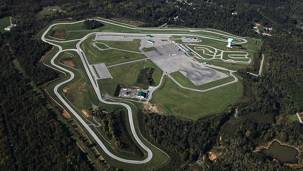
I have it in the back of my mind to host a time trial competition for front-wheel drive cars. Only. I’d call it FF/TT, and hold the race at the most challenging track for FWD cars, Pineview Run.
What makes it so challenging is something I debate with my brother. Partly it’s the uphill esses, which take the weight off the front, where you need traction for acceleration and turning. Partly it’s the long slow corners, which show up in the data as lower lateral Gs. And partly it’s I don’t know why; it’s just so goddamn slow in a FWD car.
As an example, on the original track, I drove a Mini Cooper R50 on 205 RE71R tires and struggled to get a 1:22 lap. In a Miata with the same power to weight ratio, and on similar tires, I could do a 1:18 all day long. Similarly, in my Veloster on V730 tires I can do a 1:16 on V730 tires, but a RWD car of the same specs would be doing 1:13 easy.
Now these examples are from Pineview’s original track, and the new track extension should balance the scales a little bit, being faster and longer. But it will still be more difficult for FWD cars, and that’s what makes Pineview a great place for a FWD TT.
I was thinking about how to class the cars and came up with two obvious ones right away:
B-Spec, Sundae Cup – These cars are close enough in spec that I’d lump them together and have them on similar tires.
Unlimited – The fastest FWD car must emerge as the overall winner.
There’s a chasm of performance between Sundae Cup and Unlimited, and so there should be a few classes in the middle. To determine where to divide the classes, I ran hundreds of computer simulations in OptimumLap, using Pineview’s long track. I used cars that ranged from 10:1 to 20:1 lb/hp, and choose tires of various grip levels and different aero parts. From this mound of data, I sorted all of the cars into classes separated by 2.5 seconds each.
I also tried sorting cars into classes based on 1.5 and 2 seconds, and while this would bring more parity within each class, it increases the number of classes from an easily manageable four classes, to five or six. That’s nothing compared to the thirty-something classes in SCCA autocross, but I’d like to keep things much more manageable.
In the simulations, mechanical grip was the most important factor by a long shot, and so the classing system is largely based on tires and things that affect grip. Because Pineview is a low-speed track, there are diminishing returns to adding more power. In fact, after about 10 lbs/hp, lap times didn’t change much at all. Likewise, because of the slow corner speeds, aerodynamic downforce doesn’t come into play much.
OptimumLap doesn’t discern between FWD and RWD, and so my classing system is generic to all cars. However, most racing series recognize that FWD cars are at a disadvantage, and give them a slight performance boost. For example, NASA TT gives a +1 bump to lbs/hp for FWD cars (or + .5 lbs/hp if it’s a factory built race car). I’ll do something similar for FWD cars, but I’ll modify grip rather than power, because that’s actually where the discrepancy lies.
Time trial classing
To class your car in my system, do the following:
Log the weight of your car, with fuel and driver, ready to race.
Add together your car’s maximum hp and torque and divide by two. These figures are assumed to be measured at the wheels on a Dynojet. (Using both hp and torque should put both peaky and flat-tuned engines on more equal footing.)
Divide weight by power, and save this as your Lbs/Power figure. (Which I may call lbs/hp for convention, but it always means an average of hp and torque.)
With these values, you can now find your class in the following lookup table.
Power to weight ratio and tire choice are the primary factors that determine your class. Other options move you left or right in the columns.
Modifications to classing
There are several modifiers to the class, which move your car left or right one more columns. I may come up with more modifiers, but I’d also like to keep things simple.
Tire width – For most cars, tire width falls into a standard range that’s 11-13 times the weight of the car. So a car that weighs 3025 lbs will have a tire in the 235- to 275-width range. If your car weighs more than 13x tire width, your car has skinny tires and moves left one column; If your car weighs less than 11x tire width, your car has wide tires and moves right one column.
Suspension – Coilovers allow more camber and the ability to corner weight, and so they move the car one cell to the right. If you have multi-adjustable coilovers, move two columns to the right. RWD cars with a solid rear axle move one column to the left.
Aero – Cars with aero move one or more columns to the right, depending on how much aero. But know that aero doesn’t help that much at PV.
Drivetrain – FWD cars move one cell to the left. I feel like they deserve more help than this at Pineview, but let’s start here.
You may notice that the table doesn’t include cars that are slower than 20 lbs/hp. If your car is that slow, get it to 25 lbs/hp and race in Sundae Cup. Likewise the table doesn’t include anything more powerful than 10 lbs/hp, because at this track, there are diminishing returns at higher power, so just use 10 lbs/hp if your car has more than that.
Classing examples
Here are some cars and which classes they’d fit into on different tires.
Corvette, 10 lbs/hp – Class C3 on a RT615K+, C2 on Kumho V730, and C1 on a RE71RS. (Most Corvettes have better than 10:1 lbs/hp, but this is the maximum for the chart.)
Civic Type R 11 lbs/hp – Moves one column to the left for FWD. Class C4 on RS4 C3 on V730, C2 on A052, and C1 on Hoosiers.
My Hyundai Veloster N, 13 lbs/hp – It’s FWD and has skinny tires for its weight, and so it moves two columns to the left. But I have front and rear aero, so it moves two to the right. In the end, it stays where it is. Class C4 on RT615K+, C3 on ECF, C2 on RE71RS, and C1 on Hoosiers.
ND Miata, 15 lbs/hp – Class C3 on V730s, C2 using CR-S V2, and C1 on Hoosier R7s.
Mini R56 JCW 16 lbs/hp – FWD so it moves one to the left. Class C4 on AD09, C3 on RC1, C2 on Hoosiers.
Typical Track Miata, 18 lbs/hp- Most of these have front and rear aero, wide tires, and coilovers, and so they move four columns to the right. Class C3 on RS4s, C2 on RE71RS, and C1 on SM7.5.
FF/TT or a Pineview leaderboard?
A front-wheel drive only time trial sounds like a fun event, especially at this very challenging track. I envision this as a Saturday race, with optional practice on Friday, and an optional HPDE on Sunday. (Optional days because it’s unlikely the track could be reserved for a full weekend event; Pineview is a private member club, and they have the first rights to drive.)
If this idea interests you, let me know, because it will take some momentum (and convincing Pineview’s owner) to make this happen.
But even if FF/TT doesn’t happen this year, I think this classing system works great for a leaderboard. Show up at the track whenever you want, set a lap time on any 10hz GPS device (Aim Solo, Garmin Catalyst, phone app with 10hz antenna, etc), send me the lap time and your class, and I’ll add it to the online leaderboard.
On the leaderboard I’d keep track of eight classes:
Sundae Cup – For B-spec and FWD Sundae cup cars on RA1 or RT660 or RT651 tires only (no z214, Toyo RR, etc).
C4 – Per the classing chart. RWD Sundae cup cars go here.
C3 – Per the classing chart.
C2 – Per the classing chart.
C1 / Unlimited – C1 is essentially an unlimited class, this would be for any drivetrain.
C1 / Unlimited FWD – I’d keep track of the fastest FWD separately.
A/S Open – 500 TW, no restrictions.
A/S FWD – 500 TW front-wheel drive, no restrictions.
You might question the 500TW categories, but there are quite a few Pineview members that regularly track their car on 500+ treadwear tires. Dennis, Ed, myself, and even Pineview owner Todd Milton regularly choose to drive on all-seasons. Not only are all-season tires a lot more economical, they are the great equalizer between cars, and quite a bit of fun.
I’ve tried to convince Todd that he should hold the first and last race of the year on all-season tires, but that hasn’t gotten any traction with him yet (chortle). I’d make it a point-to-point race with autocross timing lights rather than transponders, and bring the track rats and cone dodgers together to see who’s the fastest on the worst tires. That would be a great way to kick off the season in March and put it to bed in November.
I’ve had my Veloster N for a year and a half, and with two track seasons finished, it’s time for a retrospective. I’m not going to get into daily driver details, just going to review the important things; race track things.
Wheels
Most people downsize the OEM wheels from 19” to 18” because aftermarket wheels are much lighter, and 18” tires are usually about 20% cheaper. The big challenge is fitting wider wheels and tires; unless you cut the fenders and install flares, the Veloster N can’t fit wide tires. When you compare the wheel and tire sizes to other cars, the Elantra N can easily fit 245 on 9”‘ wheels, while a Civic Type R can fit a 265 on 10”. It’s just not fair.
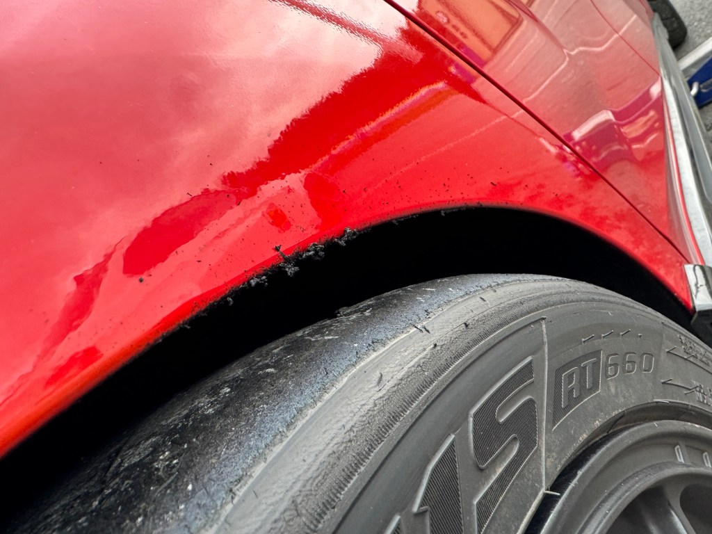
Ergo, VN track drivers typically fit a 235 tire on 18×8.5 +45. My buddy Chris was able to fit a 245 RT660 on a 8.5 +50, but he was at stock ride height. I tried the same tire on a 8.5 + 45 with 1” lowering springs, and it rubbed front and back.
On 1” lowering springs, a 245 RT660 on 18×8.5 +45 rubs front and rear. The same tire on 18×8.5 +50 will clear with stock springs.
I have three sets of wheels:
OEM 19×8+55 – Theres nothing to like about the stock wheel, it’s narrow and weighs over 29 lbs. When I wore out the OE Pirelli PZ4 tires, I put $65 Linglong Crosswind tires on these wheels, which is better rubber than they deserve.
Konig Countergram 18×8.5 +43 – I bought these because I like the black center and polished aluminum lip. They were about $300 at Fitment Industries and weigh 19 lbs. I have only used these for Kumho V730s, and they fit fine.
Motegi MR140 18×8.5 +45 – These are a bargain at $173 from Phil’s Tire. The only downside is the mounting holes are super narrow, and even 17mm lug nuts won’t fit, so you need to use spline (tuner) nuts, which I fucking hate. Anyway, the wheels are cheap and at 19.1 lbs, quite light. I used these for the 18” PZ4, Blu Trac Race, Pilot SS, and RT660.
I’ve read somewhere that reducing rotating weight is 3x more important than weight elsewhere on the car. So taking 10 lbs off each wheel is a huge benefit for acceleration and braking. Being unsprung weight, this also helps handling.
Tires
I put camber bolts in my Veloster N, and it maxes out at -1.8 degrees of camber. I understand that the DCTs can get more camber than the 6M versions, but I don’t exactly understand why. In any case, this doesn’t allow my car to get the most out of a proper track tire, and so the difference between an all-season and a super 200 is less what it should be. Or another way ofputting that is that my car goes well on shitty tires.
At this point I’ve track tested eight different tires, from cheap all-seasons, to max performance summer tires, a few 200s, and a premium 100 treadwear. All of these were properly abused on the same race track, and I dutifully collected data for comparative analysis.
I’ll list them in the order I drove them (including two tires on a friends Veloster N), and sum it up with a report card.
Pirelli PZero PZ4 – I’ve had these in the OE 235/35-19 on 8” wide wheels, and 235/40-18 on 8.5”. I felt they were decent rain tires, but otherwise just average. You need to keep the pressures high to keep them from rolling over, and rotate them frequently, as they deteriorate quickly on a dry track.
Falken RT660 – I drove these in a wider 245/40-18 on my buddy Chris’s VN, and came away solidly impressed. On an otherwise stock VN I was only .25 seconds off Pineview’s all-time FWD record. Chris’s car doesn’t have a lot of camber, but he had the tires heat cycled before delivery, and thus experienced none of the center delamination or tread splice issues that others have reported.
Maxxis VR1 R2 – The Hankook RS4s used to be my favorite dual duty tire, but it’s not always available, and rarely on sale. Maxxis VR1s are pretty close in performance, and a great second choice. I used this tire on Chris’s VN and went a little slower than I did on the RT660. On the other hand, Chris didn’t like the feel of the Falken’s and went faster on Maxxis. This goes to show you that it’s not always the outright grip that matters, and you might turn a faster lap on a tire with less grip. Feel, feedback, and confidence are important.
Linglong Crosswind UHP All Season – I bought these because I needed something (anything) to put on my 19” OE wheels after the PZ4 wore out. At $65 on sale, I didn’t expect much more than round and black, but I took them to the track just the same. The sidewalls were mush and they howled like a chorus of tone-deaf banshees, but the performance wasn’t terrible. Three different drivers flogged them all day long, and the budget 400 TW tires earned some respect.
Kumho V730 – This is a good dry track tire, but worthless in the wet. It has a NT01 feel, with great feedback and grip that’s good down to the cords. While searching for more grip, I aired them down too low and corded the outside shoulder with half the tread remaining. I can’t start these at less than 32 cold, which means they’ll come up to 41 psi hot, and so I have to pit once and air them down, which is a PITA. They are cheaper than most 200s, and if the car could get more camber, I’d use nothing else.
Armstrong Blu-Trac Race – Armstrong left the e off of Blu and the k of off Trac and the grip off a 200 TW tire. And yet this was the most fun tire I’ve tried so far. They break away very early, but are super easy to control when sliding. You can get them with a money-back guarantee, and they go on sale a few times per year. This tire puts the E in HPDE.
Goodyear Eagle Supercar 3R – I admit that I often order food looking at the right side of the menu, and so it’s not surprising that I buy tires by price. But this summer I decided to spoil myself for once and get a premium tire and set some PB laps. The grip of the SC3R was incredible, if inaudible, and the turn-in was so insanely quick, it felt like I was driving a completely different car. All the ingredients were there, but the lap times never materialized. The tires made the car feel like I had all the nannies on, and took the fun out of driving. In the end, I went a second faster on V730 than I did on SC3R. I recently traded them away for a used set of RT660s. I’ve also had the devil of a time getting my rebate, which is part of why I bought them in the first place. I’m done with Goodyear.
Michelin Pilot Super Sport – These were the OE tire on the base Veloster N (non-Performance Pack), and came in a smaller 225/40-18 size on that version. I got them for free on Facebook Marketplace with half the tread remaining. They are easy to drive at the limit, but have an unusual sound, more of a protesting whine than a painful howl. The PSS are a generation older than most 300 TW tires, but were within a second of the V730 or SC3R. I corded the outside shoulder, just like every other tire. Man I need coilovers.
The following table is how I’d rank the tires on my Veloster N. I’ll probably get some disagreements here, but I like a playful tire that lets the car dance, and lap times matter don’t as much to me as having fun.
Tire
Grip
Longevity
Price
Fun
Grade
SC3R
A+
D
D- ($325)
D
C-
PZ4
C
C
B ($175)
C
C+
RT660
A
C
C- ($250)
C
C+
Crosswind
D
C
A+ ($65)
C
C+
PSS
C
B
C+ ($175)
B
B-
VR1
B
B
C ($230)
B+
B
Blu Trac
D
A
B+ ($165)
A
B
V730
A
B
B- ($200)
B-
B
Tires by grade.
In the future I have two choices: get coilovers so that I can use better track tires, or switch to endurance tires with a symmetrical tread pattern. RS4s are the easy button, working well with camber challenged cars, and allowing me to flip them once, after I wear the outside shoulders.
The more expensive choice is to buy coilovers, which allow more camber and corner balance the car, and that would reorder my tire list completely. The negative camber would also allow the wheels to tuck under the fenders better. With that I might be able to fit 18×9 +45 wheels and 245 tires.
But… this is still a street car and I’ve ruined other cars in the past making them too track focused. I’ll revisit this conundrum in 2025.
Brakes
Muzafar Umarov manages the N Track and Autocross group on Facebook, and is a knowledgeable source on all things N. From him I learned that the Veloster N brake bias starts at roughly 70% front, but changes dynamically based on slip. Brake bias is controlled electronically for each wheel, and can shift to as much as 93% front if the rear wheels are locking.
This is both good news and bad news. If you’re accustomed to using the rear brakes to rotate the car on corner entry, you’ll be disappointed. The system essentially prevents corner entry oversteer, intentional or not. This infuriated my brother, who swore the traction control was on, even though it was turned off in the custom settings.
This also means that putting higher friction brake pads on the rear is a waste. Just as the dynamic brake bias system won’t help you turn the car on corner entry, it also won’t stop the car any faster. The sticky rear pads will just transfer more bias to the front brakes sooner. As a result, even the very serious folks at GenRacer are still using the OE rear brake pads.
And for that reason I’m also using OE rear pads, and will be for the foreseeable future. They are inexpensive, wear is imperceptible, and there’s no reason to use anything else. Life can be just that simple.
The OE front brake pads are reported to be quite good as well, and can do autocross and light track duty as long as you use the OE tires. But they are a little expensive, and the cheap hack is to use the Elantra N pads, and reuse the Veloster N shims.
But I don’t know about that, since once you upgrade the tires, you’re going to want better than OE pads. Knowing this, I switched the front brake pads to Porterfield R4-E immediately upon delivery.
This is a pad I have racing experience with, and as someone who’s never had antilock brakes on a track car before, I typically prefer pads with a lower friction coefficient. I believe the R4-E (E is for Endurance) come in around .46 mu, which is quite a bit lower than most serious race pads. As a result, they probably require more brake pressure. But I like the way they feel as I release the brake pedal, and that’s more important to me than initial bite or maximum stopping power.
Another reason to use a less aggressive pad is that several Veloster N owners have reported getting ice mode when using higher friction track pads. This can overwhelm the stock calipers and ABS system, and send the car into a panic. And so there are at least a few reasons for me to use the R4-E (the E is also for Economy).
The pads cost $210, which is $100 less than what you’d pay for most hybrid street/track pads, and half the cost of a dedicated track/race pad. I leave the R4-E on for daily driving, and they stop fine when cold and don’t squeal annoyingly like an aggressive track pad. (Although I understand some people like that.)
The way the R4-E work on both street and track remind me of the old Stoptech 301, before they switched manufacturing plants. That was a true dual duty pad, but it lasted about half as long as a R4-E. Still, they were less than half the price, and I used them without complaint for years.
Admittedly, I don’t experiment much with brakes, but Gregg Vandivert has done a ton of brake pad testing on his Elantra N. He had a problem using the Porterfield R4 (not R4-E) compound; the pads cracked and separated from the backing plates. The reason this happens is because Hyundai uses a cheap single piston caliper, and so the backing plate needs to be ultra stiff, or it flexes.
Gregg says Porterfield has two thicknesses of backing plates available, and you can special order pads with the thicker ones. Well, my R4-E pads have not cracked or separated, and so perhaps the E pads come with thicker backing plates to begin with? I will need to ask the folks at Porterfield at some point.
In any case, the brake pads are just fine for street and track driving, and they held up for over a year of both. Eventually the brakes started to fade on track, and I figured it was time to change them out. When I pulled them off I noticed they wore evenly inside and outside, and I had used 99% of the friction material without getting into the backing plates. I got lucky there.
I got everything out of them.
Moving on from pads to rotors, I’m now just onto my second set. The service limit is 28mm and that’s where mine are at the outside edge, but down near the center they are 27.2mm.
It looks like I’ll need to replace rotors every two sets of pads, but if I get pad-curious then I’ll do both at the same time so they bed in properly. I paid $140 at Parts Geek for the front rotors, while my local Hyundai shop wanted $400 for essentially the same thing. Areyoufuckingkiddingme?
Two sets of front pads and one pair of rotors works out to $540, and that covers maybe two years. I don’t know how long the OE rear pads and rotors last, but certainly longer. That’s some serious economy, and it surprises me that Veloster brakes are as cheap as Miata brakes.
Fuel and engine modes
The Veloster manual says to use 91 octane, but I use 93 most of the time, because that’s what’s available. However, many of the pumps here only have non-ethanol 90 for Premium (lots of boats and such in this area). I don’t know what the power difference is between 90 non-ethanol, 91, and 93, but it may get more power out of 93 because of the higher octane. I don’t know if the VN has the “octane learning” feature of the EN, but I’m pretty sure the ECU will pull out timing when it senses lower octane. But then again, ethanol burns at 80k BTUs, while gasoline burns hotter with 118k BTUs, and so maybe I should be running non-ethanol?
I get exactly 7.0 mpg on track at Pineview and NYST. Every time. My friend Chris is only a couple tenths of a second slower than me on Pineview’s short track (45 second lap) and gets 2 mpg more than I do. So it’s interesting to see the diminishing returns on driving the car harder. At Watkins Glen I get a miserable 6.0 mpg. In practical terms, this means emptying a 5-gallon jug every track session.
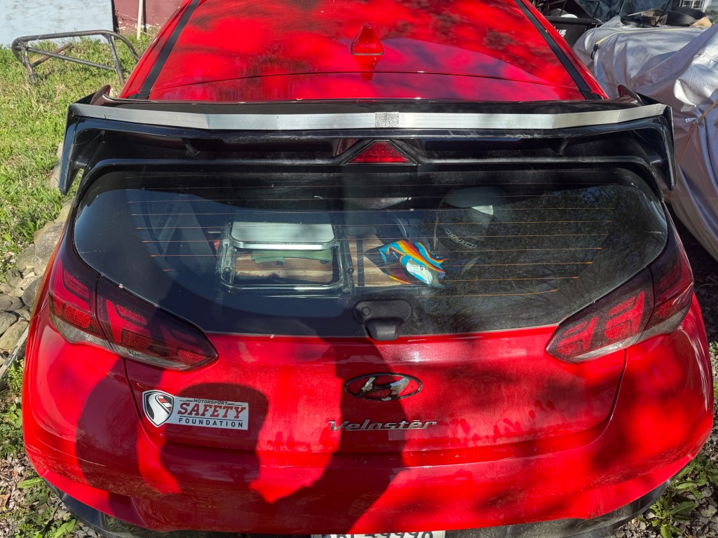
On the highway I get mostly 32-33 mpg with the N wing, and I lose maybe 1 mpg with the ducktail spoiler. With a wing on the car, it gets just under 30 mpg, which is kind of surprising, because I thought that ducktail would have more drag. I haven’t done an accurate two-way test over a distance though.
The Veloster N has four different pre-set driving modes that change engine response, exhaust note, suspension stiffness, steering quickness, traction control, rev matching, and the electronic limited slip diff. I only use one of the pre-set modes, Normal. Economy mode doesn’t do shit, and the performance modes are a collection of settings I’d never use together.
Thankfully Hyundai made a N Custom mode that allows you to adjust each setting individually and save it as a custom setup. Mine has the suspension set to soft, and a quiet engine note with none of the pop and burble nonsense. I turn all of the nannies off, including rev matching, and max out the eLSD. I haven’t decided which of the three steering modes I like best, but I can change that on the fly using the touchscreen.
I use the Normal driving mode when I’m on the street, or when I am on track and it’s raining a shit storm. Compared to my N Custom mode, Normal is about a second faster in the wet and about 1.5 seconds slower in the dry. So I definitely appreciate having the options.
I dyno tested all the engine modes and they put out the same power. Eco mode is supposed to limit boost pressure, but it doesn’t make a difference on my car. I got 244 hp at the wheels on a Dynojet, and that’s 10 more than I expected.
Someone said the different engine modes don’t change power, they change how the engine responds. But given how the modes are identical on the dyno, I’m skeptical, I’ll A/B test engine response on track and see what the stopwatch says.
Finally, there was a recent software update that changes a bunch of things in the N Custom mode. I like the new layout, and appreciate that Hyundai is still making updates to a car they discontinued. I keep the updated software on a keychain USB drive in case I meet someone with a EN, KN, or VN that hasn’t made the update yet.
Track warranty
Arguably the best reason to buy a Hyundai is for the 10-year powertrain warranty. I bought mine as a Hyundai-certified pre-owned car, and so I’m covered until November 2032. I also upgraded to full bumper to bumper coverage, and so if anything goes wrong with my car in the next eight years, someone else is fixing it. And because this is a N car, the warranty extends to track use.
In fact, I’ve already used the warranty. The engine blew up on track at Waterford; Hyundai picked it up at the track, fixed it, and delivered it to me 500 miles away. They even paid for the rental car to get me home. I suspect in the next 8 years I will be using the warranty again.
Hatchback life
There aren’t a lot of sports cars that have enough room to transport a set of tires inside the car. Of course most 4-door sedans can do this, with two in the boot and two on the rear seats, but how many proper track cars can swallow a set of slicks? The Subaru-Toyota BRZ-86 was apparently designed to carry a set of track tires in the back, and I’ve seen four tires disappear inside a BMW 1-series. So I imagine that most BMW coupes can manage this as well.
Hatchbacks have the advantage here, and when you fold down the rear seats, even a diminutive MINI Cooper can carry four tires inside. But can you name any track car that can transport eight tires inside? With the space-saving Modern Spare in the well and one on the front seat, that’s actually nine!
Shocker! Seven in the back and one in the front.
The first time I went down to the A2 wind tunnel, I transported three splitters, five wings, two spoilers, a diffuser, boxes of tools, spares, and other parts inside the car and drove the 10 hours to Moorseville. Try that in any other car you’d actually take to a wind tunnel.
That’s a lot of junk in that trunk!
And if this wasn’t enough space already, I added a trailer hitch so that I can use a cargo tray or small trailer. The Veloster trailer hitch was designed for the base model Veloster, and required some modifications to fit my car.
Aerodynamics
My Veloster has been to the A2 wind tunnel twice, and now I know more about hatchback aerodynamics than I ever dreamed I would. The OE body has a drag of .416 and makes a tiny bit of downforce, which is pretty surprising, since most cars make lift.
Front downforce was easy to get, and even a flat splitter made 135 lbs of downforce at 100 mph. My curved splitter made 195 lbs, and coupled with upper and lower canards and hood vents, total front downforce was north of 300 lbs. And this is without cutting vents into the fenders or extracting air behind the wheels, which you would do on a proper race car, but I may never get around to on a daily.
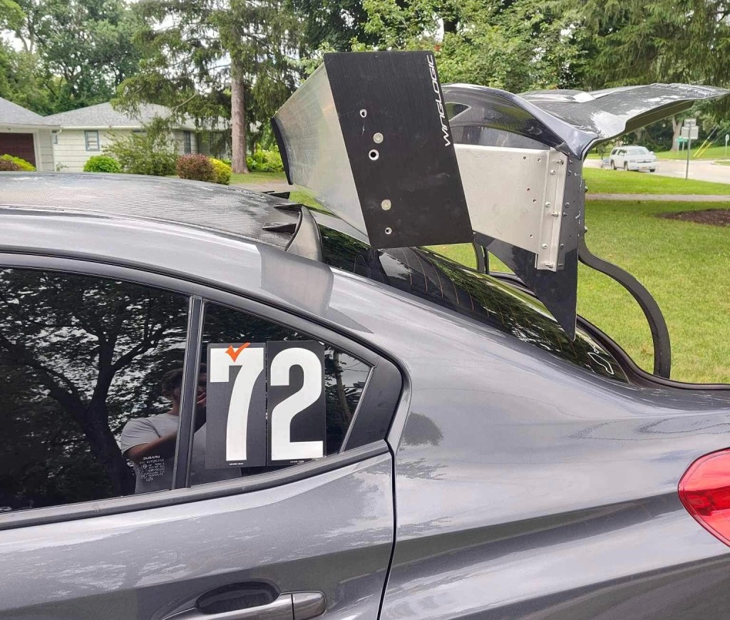
At the other end of the car, wings didn’t perform as well as I expected, and even the Kamm-back shape is a compromise over a proper coupe or fastback. As such, most wings up to 55” span had lift-to-drag ratios less than 4:1. A 70” Wing Logic gave the best results at 7:1, which is more a function of the wingspan than the shape of the wing; it’s obviously important to get the ends of the wing into clean air where they can get away from the hatchback roofline.
If wings were disappointing, spoilers were a revelation, as they made both front and rear downforce. (Wings reduce front downforce through leverage; Spoilers aggregate pressure over the l roofline, and some of that is in front of the rear wheels.) Spoilers can’t get as much total downforce as a wing, but they work surprisingly well if you’re not going to add a splitter.
The biggest surprise was that adding a 1” Gurney flap on the OE N spoiler gave a better L/D ratio than all but the largest wing.
1” angle aluminum Gurney flap. In the wind tunnel I used duct tape, here it’s fastened with rivets, and in the future I’ll drill those out and use rivnuts for easy on/off. Notice I also added slightly taller end plates, but I didn’t do that in the wind tunnel.
At 100 mph, the OE wing makes 30.8 lbs of downforce and loses 2.5 hp due to drag. With the wicker-kicker it makes an astonishing 123.6 lbs of downforce and uses 8.3 hp. (These numbers are compared to the base model, which has a roof extension, but no wing).
Rear view of wicker, kicker, Gurney flap. I’ll probably paint it black at some point in the future.
The Gurney flap information isn’t (yet) in my wind tunnel report, but there’s over 50 pages specific to the Veloster N, going nose to tail on aerodynamic parts, simulated lap times, and a lot of discussion.
I also did some practical testing of wings and spoilers at Pineview Run and NYST. The short story is that my Veloster went 2.5 seconds faster with rear downforce alone. Given that, I wouldn’t even bother adding front downforce unless you have a really significant wing to balance it out.
Conclusion
In the past year and a half I’ve done probably 30 track days in my Veloster N; I’m still smiling. It’s got enough cargo capacity for everything I bring to the track, and a comfortable ride that makes long-distance track treks a pleasure. It has adequate power, and handles better than it should. Even on track like Pineview, which has a lot of long corners and uphill switchbacks that punish FWD cars, it’s fast and fun to drive.
As track cars go, it’s economical. It doesn’t need expensive brake pads or ultra grippy tires, and seems to work just as well with mid-performance items. If you want to keep the warranty, you can’t modify engine parts or tuning, which leaves very little to spend money on. Except gas, as it is pretty thirsty.
The funny thing is, I’m actually looking forward to when the car is out of warranty, and I can install a bigger turbo. With a larger turbo, all the bolt ons, and a ECU tune, it might get down to a 10:1 lbs/hp ratio. Then I’ll gut it, cage it, and race whatever dumb series will have me. But I’ve got 8 years of wringing the snot out the stock engine, and I’m not at all disappointed with that.
I daresay I’m forming an emotional attachment to this car! It’s the amalgamation of so many cars I wanted and never bought: It’s the Honda CRX I pined for in college, but modernized and powerful; It’s the later CR-Z with double the power and nearly the economy; It’s the 3-door cousin of a MINI Clubman JCW, but with better aerodynamics; It’s as weird as the M Coupe “clown shoe” I nearly bought, but easier to live with.
And it’s so much fun! I love tossing the car into an early apex, forcing it into a four-wheel drift, and then digging it out with the front wheels. It’s Miata like, in its combination of economy and ability to bruise egos everywhere it goes. If you have a BMW M car, Corvette, or Porsche, you’d better be a decent driver, because the hurt machine is coming though!
This is probably the last car I buy that isn’t an electric self-driving killjoy mistake, and so I’m going to continue to modify it for more fun. I’ve already removed the rear seats and put in a flat cargo floor. Next I’ll install a harness bar and race seat. Sometime this winter I’ll figure out a DRS dual wing, because hitting a button on the straights is a plus one to fun. And maybe I’ll hook that up to an adjustable splitter as well. Let’s see what happens in 2025.
In a previous post I put various wings and spoilers on my Veloster N and tested them at Pineview Run. What I found was that a ducktail spoiler or single wing was about .7 seconds faster than the OEM N spoiler/wing. And then I tried a dual element wing, which was another .6 seconds faster.
Pineview is a small, slow track, and there are only a couple corners where aero matters, and so 1.3 seconds is a significant difference. I opined that on a longer track with faster corner speeds, the lap time delta might double.
I got a chance to put my money where my mouth is at private open track day at NYST. The track closed for the season a couple weeks prior, but somehow Brad at S2K Takeover got his group a bonus round, and they invited me along. It was cold and damp at the start of the day, and this affected things slightly, but I got in a lot of consistent runs as well.
Rear aero options
For this event, I didn’t have much front aero on my Veloster N, just a hood vent and an aluminum undertray. Those are mostly for cooling, but they might provide around 60 lbs of front downforce at 100 mph. I have splitters and canards aplenty, and can get five times the downforce with those, but I wanted to test the exact same car I was using at Pineview last time.
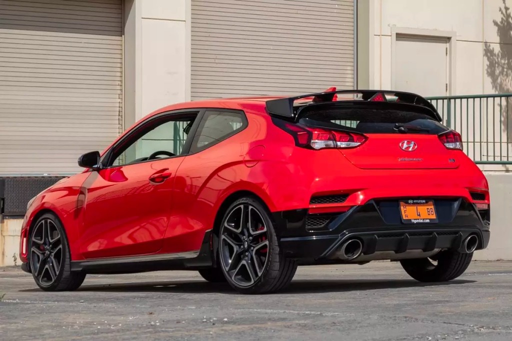
Lots of rear aero options, and nothing on the front. Tires are 235/40R18 V730.
Well, not exactly the same, because I didn’t bring the ducktail spoiler. At Pineview, the single wing was about the same performance, and so I left the ducktail at home. This would allow me to make faster setup changes, as I could keep the same roof extension on for every configuration.
If you are a regular reader, you know I’m a shit disturber; I like to challenge the status quo, and disprove common misconceptions using data. That’s another reason there’s no front aero on the car. Adding rear aero alone on a FWD car throws the aerodynamic balance out the window, and is the opposite of what most aerodynamic pundits suggest.
The rule of thumb is to match your aero balance to the chassis balance, so that you don’t change the balance of grip as the car changes speeds. And so if your car has a 50/50 weight distribution, then you add the same amount of downforce front and rear. Or in the case of this FWD hatchback, if you have 67% of the weight on the front, then you should add twice as much downforce on the front as on the rear. But I purposefully didn’t do that; I only added downforce to the ass end.
I tested seven rear aero options:
No aero – The base model Veloster didn’t come with a wing or spoiler, just a roofline extension. I built my wing mounts on top of this, and so the no-wing setup has two vertical wing supports. This might provide some stability in yaw, but they wouldn’t add downforce or affect the lap times much.
Single wing, 0 degrees – This is my DIY S1223 wing, which I recently modified with glassed-in endplates. This is also the lower wing for all of the dual element wing tests.
Dual wing 0/0 – This setting adds an upper wing element at zero degrees. This represents a dual wing at the lowest drag setting.
Dual wing 0/26, standard gap – I then set the upper wing to 26 degrees. This is a fairly conservative angle of attack for a dual element wing.
Dual wing 0/26, small gap – I kept the angle the same, but moved the upper wing down (closer to the main wing) and forward, so there was more overlap between the wings. This is the only wing setting where I used this gap and overlap.
Dual wing 0/40 – I put the gap and overlap into the original position, and then raked the upper wing to 40 degrees, which is typically the maximum angle you can use with a dual element. At this AOA I’m flirting with flow separation, but what can I say, I’m a flirt.
Dual wing 0/40 Gurney – I added a 1/4” Gurney flap. At high angles of attack, a Gurney flap can often help keep air attached. This setting should have the highest downforce, but also the most drag.
Let’s see how these compared in lap times, from slowest to fastest.
No wing 1:41.546
I tested the wingless car on the last run of the day. The track was in perfect condition by this time, now completely dry and warmed by the sun. I was also driving at my best, with enough laps under my belt that I wasn’t losing time anywhere for silly mistakes or a lack of reference points. And yet I set my slowest lap time.
The problem was mostly that I’d gotten used to rear aero, and without it, the car felt sketchy. On my best lap, the rear end got scary loose while braking on the front straight. And then I almost shit my pants braking into T5, as the car skidded in a way I hadn’t experienced before. I intentionally drive a tenth under the limit at this track, and I honestly thought I was about to put it in the grass.
That nervousness braking into downhill corners may be partially down to the Hyundai’s dynamic brake bias, which senses wheel speeds on each corner and then loads more and more front bias as the rears sense lock. This can put up to 93% of the bias on the front tires, making the rear end rather irrelevant. Without rear aero, that balance shifts earlier.
So let’s move on from braking zones to corners, and in the slower ones, the non-aero car handled the best and was the most fun to drive. Rather than forcing the car into rotation early in the corner, I could just lift a little and get a mid-corner pivot.
From start/finish to T5, the cars were very evenly matched, but from the downhill braking zone in T5 to T11, the car was 1.5 seconds faster with a single wing than without. Sans wing, I had less confidence in turns 8 through 11. From T12 to the end of the lap, the cars were again very evenly matched.
Red is single wing, blue is no wing. They are pretty evenly matched in the slow corners, but the non-aero car loses ground in the high speed sections.
If you look at the speed trace, you’ll see that right around 52-54 mph is where the difference is; go faster than that, and you want a wing, go slower, and you don’t. Ergo, using rear aero alone on an autocross course could be useless, but on a race track, you definitely want it.
Double wing 0/0 1:40.370
Most people wouldn’t set their dual wing to zero degrees top and bottom, it doesn’t take advantage of the convergent gap, which allows more secondary wing angle. Where you see this setting is in Formula 1, when the upper wing goes into DRS mode.
And that’s exactly why I wanted to test this setting. Next year I plan to build a DRS upper wing, and I wanted to see what the speed advantage was on the front straight. So here’s how that shakes out.
The DRS 0/0 double wing had an average top speed of 107.4 mph, while the 0/26 setting had an average of 106.8 mph, and the 0/40 had an average top speed of 106.4 mph. So DRS was worth about 1 mph from the highest to lowest drag settings. This doesn’t take into account that the higher downforce wings would have a higher min speed through T18, so let’s call DRS a 2 mph advantage on this track.
DRS 0/0 in blue, high downforce 0/40 in red. You can see the top speed advantage of the low-drag setting, but this is offset by being able to brake later with more downforce.
Surprisingly, that’s not worth a lot in a lap time, as the reduction in drag isn’t noticeable until about 88 mph, which happens about half way up the front straight on the 3rd to 4th gear shift. From there until the braking zone is where DRS makes a difference. Still, DRS sounds like a fun project, and on a track like Watkins Glen or VIR, the drag reduction would be more worthwhile.
Single wing 1:40.081
The single wing is the bottom wing for all the dual wing setups. It’s my DIY S1223 with a 1/2” Gurney flap. In the wind tunnel, it was nearly the same downforce as a 55” 9 Lives Racing wing (185.4 lbs) and 55” PCI wing (182.5 lbs).
With the wing on, the car was much more planted in the braking zones and in the fast esses. The downside is that is the wing took away some of the fun in the low and medium speed corners. For the gain in lap time, and especially the braking stability, I’ll take that trade.
If I look at the theoretical lap times, there’s a full 2 seconds between the single wing and no wing. And this is without changing wing angle at all. If I had added more wing angle, the car would have turned an even faster lap time.
But let’s get back to the real data, and that was that the single wing at zero degrees was 1.5 seconds faster than no wing. This is just over double the delta I saw at Pineview, and so I guess I was right about that prediction. And with that, I’ll make another prediction, which is that this wing would be worth 3 seconds at Watkins Glen.
Double wing 0/40 Gurney flap 1:39.970
You may recall that the lower wing has a Gurney flap on it already, and for this run I put a 1/4″ Gurney flap on the upper wing as well. The upper wing measures 4.7″ chord, and so the wicker is about 5% of the chord, which is a typical size.
This configuration drew the short straw, because the track was cold and damp when I tested it. Top speed was down a hair from the other 0/40 test runs, but not as much as I thought it would be.
I’d like to re-test this one at Pineview Run, as the extra downforce might have some benefit in slower speed corners. But given that the 0/26 setting was faster, I don’t think there’s a reason to use double Gurney flaps and a 40 degree angle on this car, unless I add front aero.
Double wing 0/40 1:39.447 and 1:39.435
I did several laps with the Gurney flap on and then quickly pitted, ripped it off (it was duct taped on, just like I would in a wind tunnel), and went right back out on track again. Although the track was still damp, the conditions wouldn’t have changed much in those 60 seconds, and so I feel the comparative data here is really good between with and without the Gurney flap on the upper wing. The data shows that there’s about a half second between them, and no Gurney on the upper wing was faster .
On the second to last run of the day, just before testing the single wing, I retested the 0/40 dual wing, because I didn’t feel I gave it a fair shake on a partially damp track. The best lap was only .012 seconds faster, and so I think there wasn’t that much time deficit in the damp track after all.
Double wing 0/26 small gap 1:39.230
I wanted to see what would happen if I changed the size of the gap between the wings, and the amount the top wing overlaps the bottom wing. It would be better to run a sweep of offsets in a wind tunnel, but I figured what the heck, I’ll make one radical change and maybe I’ll notice a clear signal in the deltas. I did not.
The smaller gap had a slightly faster top speed on the front and back straight, but the differences were so minor I can’t attribute it to drag reduction. But the minimum corner speeds were all slightly less than with the larger gap, and maybe this is a lower drag, lower downforce arrangement after all. I can’t say for sure, and with lap times this close, kinda don’t need to retest this one.
Subjectively, I can’t say I felt huge difference between any of the 0/26 settings and 0/40 settings. They all made the car a little more stable, and required a little more effort to turn the car. But if you changed wing angle or Gurney on me without knowing, and sent me out on track, I wouldn’t know which I was using.
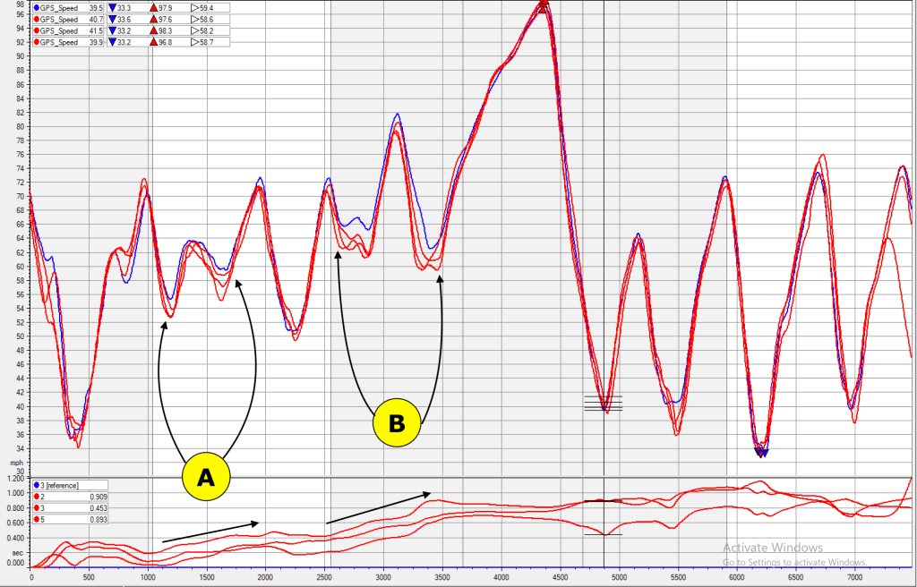
Double wing 0/26 1:39.104
The fastest laps were set with the top wing at 26 degrees with the standard upper wing gap. These laps are shown here in blue vs the 0/40 runs in red.
A – You can see the 26-degree angle has less drag and a higher top speed than the 40-degree.
B – The only place the 40-degree angle has a clear advantage is in the carousel before wheelie hill. More downforce means a higher minimum speed all the way around.
C – For whatever reason, the lower wing angle carried a higher speed through the esses.
Other than those areas, there wasn’t a lot to choose between them. Given that, there’s enough evidence to say that somewhere around 26 degrees is the best setting. Certainly the 40 degree angle was slower, as was zero degrees.
It’s funny, that when I originally built this wing I set the upper wing to 30 degrees and made no provision for adjustment. I was simply testing a proof of concept at that time, but damnit that might actually have been the best setting.
Conclusions
Here are all the fastest laps and theoretical laps for each configuration.
Aero
Best lap
Theoretical
FrontMPH
Conditions
No wing
1:41.546
1:41.192
108.3
Dry
Dual 0/0 DRS
1:40.370
1:39.903
107.6
Dry-ish
Single wing 0
1:40.081
1:39.217
107.3
Dry
Dual 0/40 Gurney
1:39.970
1:39.693
107.0
Damp
Dual 0/40
1:39.447
1:39.061
106.8
Damp
Dual 0/40 retest
1:39.435
1:38.785
107.2
Dry
Dual 0/26 small gap
1:39.230
1:38.651
107.7
Dry
Dual 0/26
1:39.104
1:38.506
107.6
Dry-ish
In the previous article, I forecasted that the single wing’s .7 second advantage and the dual wing’s 1.3 second advantage at Pineview might be worth double at a longer track, and it was almost exactly that. Like Pineview, NYST had only has a few corners where aero matters, and on a track with more fast sweepers, the advantage might double again
So I would also guess that the single wing’s 1.5 second advantage at NYST might be 3 seconds at Watkins Glen. However, I wouldn’t extrapolate this and say that the dual element wing would go 5 seconds faster at Watkins Glen, because the double wing is pretty draggy.
A single wing is more efficient, and a longer wing span might give similar downforce as the double wing at 0/26, while also having less drag. A single wing is also a lot easier to optimize, with just the angle of attack, height, and setback distance to monkey with. The dual wing has twice as many variables, and hitting the sweet spot may be down to luck. I’ve started building a larger MSHD, and I’ll test that next year, along with a new DRS wing.
Speaking of DRS, it seems like I’d want to have three settings:
Low speed – In slow corners, the car doesn’t benefit from rear aero, and it’s more fun to drive without it. I’d activate DRS at 50 mph and under.
Medium speed – For corners above 50 mph, I’d put the wing into full downforce mode.
DRS – On any significant straight, I’d go back to the low-drag setting.
Another discovery from this test is that I’ve found the tipping point where adding rear aero stops making the car go faster. This will help me figure out how much rear downforce I need when I put my splitter and canards back on. Those items are worth about 300 lbs of front downforce at 100 mph, so in order to achieve the same balance I found in this test, I’ll need to add at least that much more downforce in the back. Here’s why.
My car weighs 3200 lbs with me in it, and because I’ve removed some weight from the rear, the weight balance is about 67/33. So that’s 2144 lbs on the front tires and 1056 on the rear. The typical aero rule of thumb is that if I add 300 lbs of aerodynamic downforce, then I should split that 200 front and 100 rear. This retains the same chassis balance and mechanical grip that the engineers designed.
However, the fastest configuration I tested was with 60 lbs of downforce on the front (the hood vents and undertray) and probably 240 lbs on the rear. This adds up to 2204 lbs on the front and 1296 lbs on the rear, which works out to a 63/37 balance. Mathematically, I’ve moved the grip 4% rearwards at speed, using aerodynamic downforce. When I add my splitter and canards, I’ll want to be in the same range.
Now of course none of this make logical sense. When you put rear downforce on a FWD car, it takes away from the front tires, which is a problem because they are doing all of the steering and accelerating. But logic be damned, the reality is that I went 2.5 seconds faster with way too much rear aero bias.
If I did this same experiment on a RWD car, the results would likely be even more dramatic, because the rear wheels are responsible for acceleration and have more weight on them for braking. This supports the case for having heavily rear biased aero on a RWD car as well.
When you load a car with too much rear aero, it understeers in fast corners, but also makes for a safer and more stable car that requires fewer corrections when you lose control. The downside is the car will be boring to drive and harder to turn. But that’s what the brakes are for.
If you don’t care about lap times and want a car that is fun to drive, set your aero balance however you want. But if you care about lap times, ignore the rule of thumb and see what happens when you keep adding more and more rear downforce.
One day I’ll have enough information to write an in-depth article on aerodynamic balance, but until then, chew on this nugget: if you like the way your car handles, you don’t have enough rear downforce.
CJ Oldham began autocrossing in 2012 with a V6 Camaro. Two years later he bought a 1993 Miata, with the intention of running the popular ES class. However, the one-wheel peel was no good for dodging cones, and this lead him to installing a 1.8 BP4W motor (VICS not VVT) and drivetrain.
An intermediate stage of the car with 1999 drivetrain and mild aero.
While the 1.8 was an improvement, CJ wanted more power. He looked at Kmiatas, but had seen some people have issues with that swap, and in the end, taking an inline four out and replacing with another just had no interest for him.
CJ’s dad is also a Miata guy, and had an MSM with typical mods. But as it goes with dads and sons, CJ didn’t go the same route, and he chose a Rotrex supercharger. This would fit with his goal of keeping things simple, by using as many Miata parts as possible.
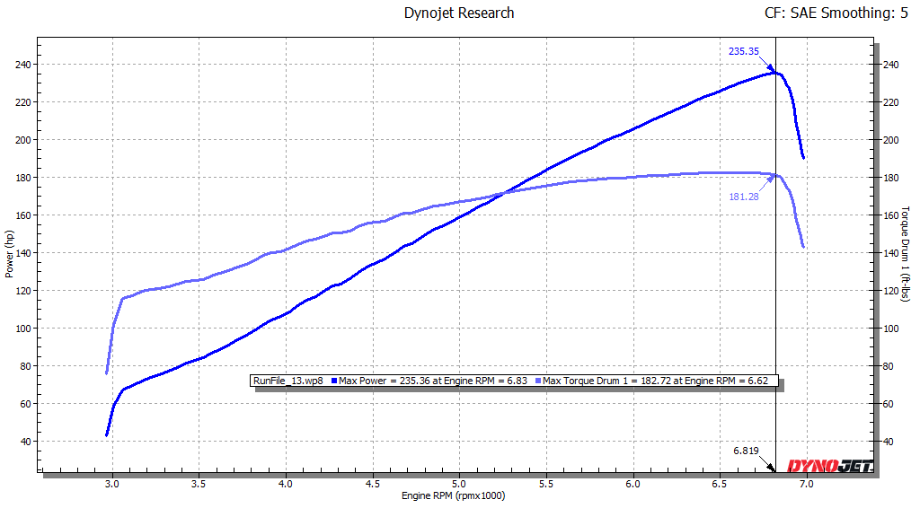
Which is not to say the build was easy. Apparently Trackdog Racing had a new machining vendor at the time, and this caused the engine to have an appetite for belts. But once the belt alignment was sorted out, things have gone swimmingly. Check out the dyno graph, with 235 hp and 180 torque at the wheels.
This is the kind of linear power that makes a car easy to drive off corners, and a demon on the straights. Yes please.
You can see from the dyno chart that the Rotrex supercharger builds power linearly from down low. Looking at that torque curve, which peaks at redline, I have to wonder how a BP05 (1994-97) would do in comparison, possibly not much different.
The gradual buildup of power is kinder to the driveline, and as the revs rise, the boost builds, and you have turbo power at the top end. As good as modern turbos are, they still rely on exhaust gasses to spool up, whereas a supercharger gets going immediately. Theoretically, the SC should have better throttle response and modulation low in the rev range.
How important is that? Speaking from personal experience, there was that one time at band camp (Pineview Run) when my normally aspirated 1.6 Miata beat a K24 Miata and took its lunch money. Stefan, the owner of the K24 (of Napp Motorsports) turned faster lap times in my normally aspirated 1.6 BP than he did in his 2.4 liter K. Hell, we both did. If you don’t believe me, I do a deep dive on the data in that article, and what it comes down to is we were both sooner to full throttle, and that was more important than top end power later on. Less is sometimes more.
But even if gradual power is easier to drive, and easier on the clutch, transmission, and ring gear, there’s no way you’re going to get a NA6 driveline to survive a Rotrex. Like any sensible person, CJ had already replaced the 6″ ring gear with a later 7″ ring and pinion. He also added a Torsen, which was really the prime motivator for the whole project. To this he added a Supermiata organic clutch and lightweight flywheel.
The final drive has a 3.9:1 ratio, which gives a theoretical top speed of 150 mph at 7000 rpm. Personally, I might opt for the 4.1 because that’s still good for 143 mph, and since nobody wants a 4.1, they are a lot easier to find and replace. The 3.9 is going to buzz less on the highway, though.
CJ is not one to scrimp on anything, and so he has Xidas in 800/500 spring rates. Some people might say those springs are on the lighter side for a car with aero, but I heartily approve of a softer car.
Front brakes were upgraded to Wilwood BX11, but since modifying the car for NASA TT4, he’s supersized to the BroFab Bigger Brake Kit with 1.25” AFCO rotors. The rear brakes are NB Sport rotors with NA6 calipers. Wheels have been similarly upsized from 15×9 FM Kogekis shod with 225/45 R15 V730s to big boy 15×10 Dekagrams with 245 Toyo RR’s. This is a proper Miata.
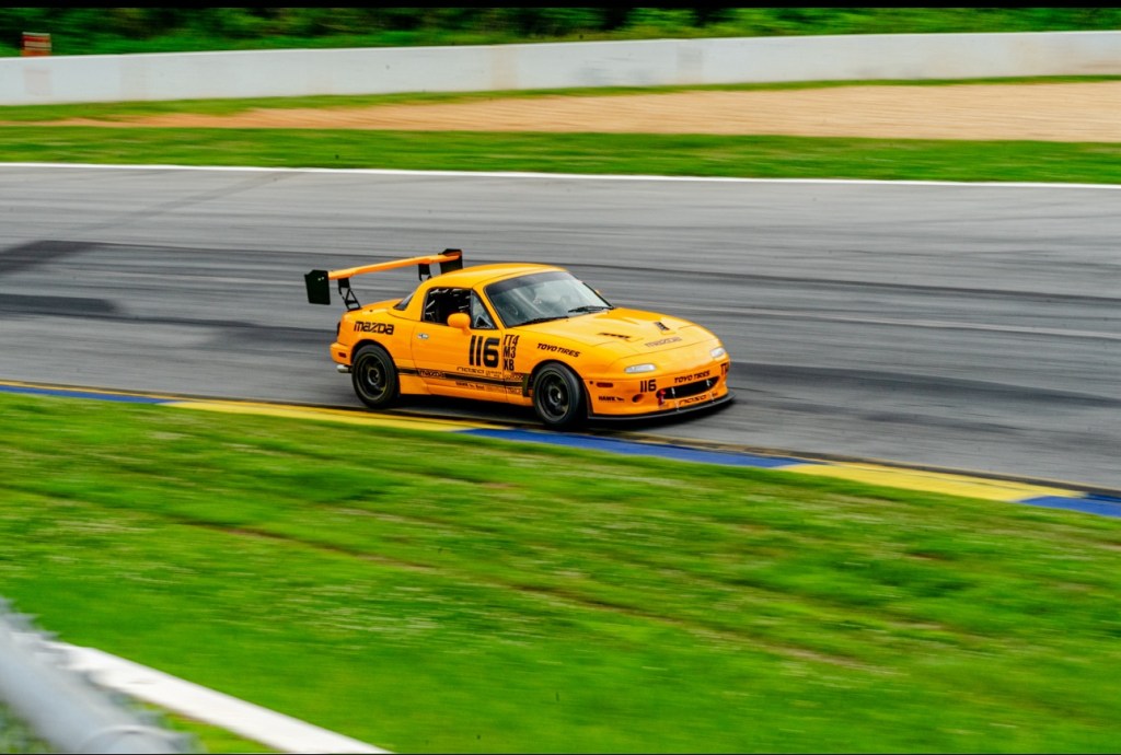
Done right, this is what a track Miata looks like. Pic by RogoPhotos.
CJ hasn’t gone off the deep end adding lightness, and in fact has all of the sound deadening and carpet still in the car. As such, the supercharger whine is quite subdued and sounds more like a soft jet engine than the whirling and whining of gears. The car weighs in at 2500 lbs with driver, and that calculates to around 10.6 lbs/hp. At the speeds this car is capable of, you’d better have some aero, so of course it does.
Aero
CJ Oldham designs and manufactures most of his parts. He went to school for nuclear engineering, but has always had an interest in the mechanical/aerospace side. And it shows. He starts by scanning the car with Revopoint products, and then designs most of the parts in Fusion 360. This allows him to rapidly produce 3D printed parts with great accuracy.
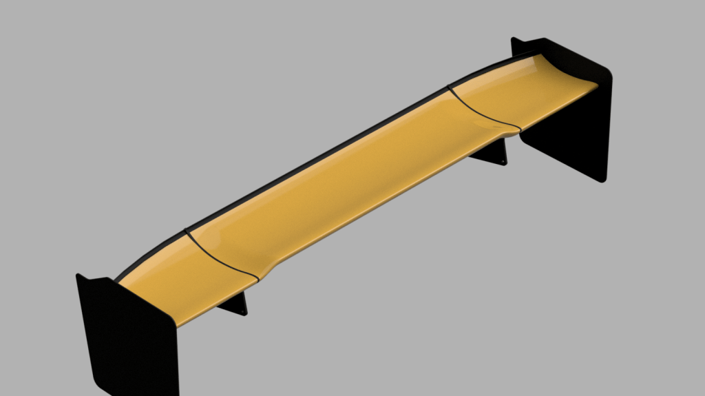
64 x 11 MSHD with tapered ends. It won’t surprise me if this is 700.5 square inches.
For example, there’s his wing. After hearing about about the MSHD airfoil, I added it to my article on Car Wing Comparisons and planned to make my own shortly after. Damnit if CJ didn’t beat me to it! My construction methods take slightly longer, while he was able to quickly print a wing in ASA. He chose a 64×11 size, and when you factor in the slight taper at the ends, you’d bet it fits exactly within the GLTC maximum size. That level of detail makes that you question how many rulebooks he’s reading.
Indeed, he also has 12″ side skirts, which are the maximum size allowed in the Max category for SCCA Time Trials racing. This is a person who’s level of detail extends in all directions, including a very lawyer-like reading of many rulebooks!
Side skirts are 12” total, to SCCA TT Max 3 specs.
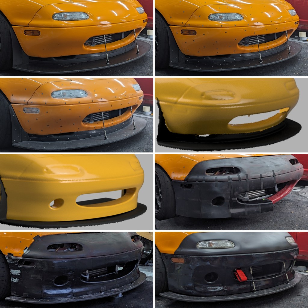
Of all the masterstrokes on this perfect Miata, the NB-esque nose on his NA Miata is what does it for me. Big plastic airdams are the lazy man’s way to improved front end performance, and to most people, they look like Tupperware. But CJ shows not only his ability to design function, but a pleasing form. Take a look.
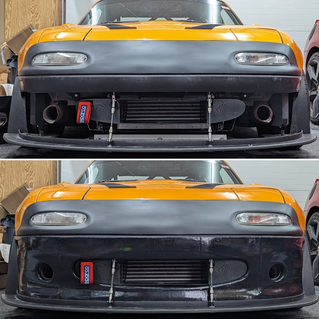
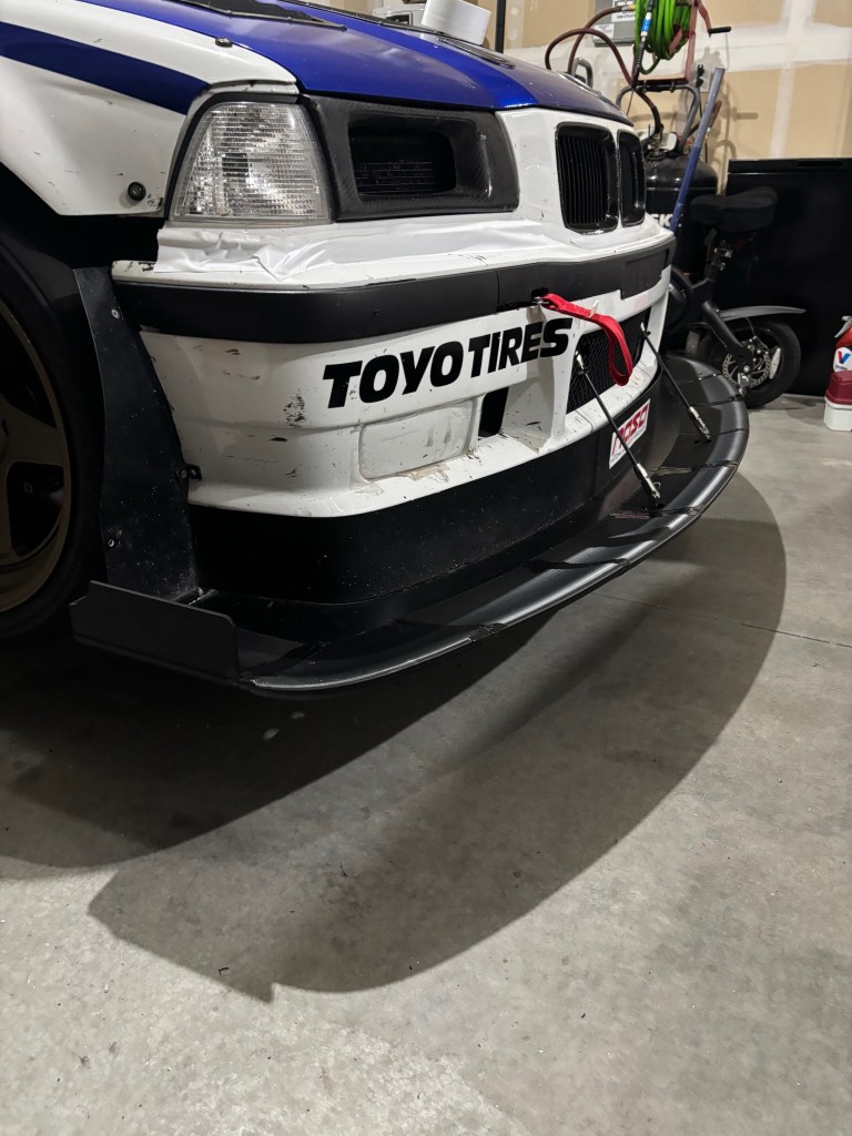
In the image above, I especially like the pic that shows the red NA nose underneath the new one. You can see how much more coverage CJ’s nose has by comparison. In the pics below, you can see that the Racebred splitter, front tire spats, and brake duct holes were clearly not afterthoughts, and integrated nicely.
A peak behind the curtain shows a lot of thought went into cooling the engine and brakes.
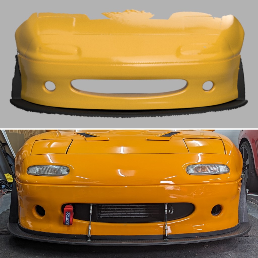
After mocking everything up, CJ did a great job finishing the work, which results in a near OE finish. Bravo my man, brav-fucking-o. It’s not just the nose that is 3D printed, but the hood and fender vents, as well.
From scan, to plan, to painted, it’s top-notch work.
CJ and his dad have done all the work themselves. Other than going to a shop for dyno tuning and alignments, it’s all DIY. I just love that spirit, and the execution is near flawless. Damn dude, you just totally raised the bar.
You don’t see many Miatas in TT4; they just aren’t fast enough. But this one is. Pic by RogoPhotos.
When I built my DIY S1223 wing, I chose a wing span of 53.15” and a chord of 11”. The chord was chosen just so I could say “this one goes to eleven,” but the reason I chose such a short wingspan was so that I could later make it into a dual-element wing. You see, you can buy a 135cm (53.15”) wing on Amazon or eBay for $60 or less, and I had that in mind from the beginning.
The other advantage of a short wing is not bumping into it. I have a decent sized “race barn”, but the garage door isn’t very wide and you’d be surprised how often a wing is just a pain in the ass. Or head.
The short wingspan and large chord combine for a low aspect ratio, and that’s not a recipe for performance. High aspect ratio wings are generally better because they suffer less from the detrimental effects of wing-tip vortices. Just the same, I had good reasons to build it this size, and so let’s get onto the dual wing aspect.
Dual wing end plates
To mount the upper wing I made new larger end plates and suspended the upper wing between them. In the past I always made end plates out of street signs, because I can get them for $1 per pound at my metal recycler. But for this project I decided to use marine plywood, which is considerably stronger at the same weight, and the additional thickness should allow me to reduce drag. Say what?
You might think a thicker end plate is more drag, but because I’ve shaped them as an airfoil, it should be less. That is, the leading edge is rounded and the trailing edge tapered to a sharp edge.
Rounding the leading edge it’s important, because it keeps air attached. For example, when the car is sliding through a turn, the car is in yaw, and airflow hits the end plate an angle. On an aluminum end plate, you might get flow separation on that sharp edge. However on a thicker end plate with a rounded nose, airflow should stay attached for longer.
The leading edge of the end plate is well rounded, and should help air stay attached longer when the car is in yaw.
I also tapered the trailing edge of the end plate on the inside. This, combined with the rounded leading edge, forms a curve like an airfoil. This should accelerate air under the wing, which drops the pressure further and creates more suction.
The trailing edge of the end plate is tapered to reduce drag and promote more suction inside the wing. Note that the bottom wing has a Gurney flap, and the gap is large because of that.
For initial testing, I set the upper wing at a fixed 30 degrees. I honestly didn’t know if this was going to work or not; I suspected that the extra downforce could make things worse, and I was sure there’d be more drag. So I wasn’t going to put effort into making the upper wing adjustable for gap, overlap, and angle, until I’d tested it.
Now if you’ve been reading my other articles, you know that it’s important to set the gap and overlap correctly, especially since the bottom wing has a Gurney flap on it. Putting a wicker on the bottom wing can increase downforce and L/D ratio, but the gap can be finicky. To avoid that I eyeballed a large gap and set a conservative angle of attack.
The main pieces of the wing assembly include the wing mounts, which are glassed into the roof extension.
When all of the parts were completed, I weighed the lot: The main wing weighs 6.6 lbs including the bottom mounts, end plates, and Gurney flap; The upper aluminum wing is 4.6 lbs; The roof extension with wing mounts weighs 7.2 lbs. When I put it all together, that’s 18.4 lbs. Total cost was maybe $150.
For comparison, a 55” 9 Lives Racing wing with The Deuce kit, plus universal hatchback wing mounts would cost $1800 and weigh north of 30 lbs. And so I’ve saved a lot of money and weight. But I also did a shit ton of labor, and I can tell you right away it’s cheaper to buy one than to make one.
Note that the OEM spoiler/wing on the Veloster N weighs a bit over 11 lbs. When you consider my double wing is only 7 lbs more than that, it’s pretty damn light.
Testing
I tested the dual wing at Pineview Run, with the long track extension. This isn’t a fast track, and there are really only a couple turns where aero could potentially help out, and one straight where drag could come into play. I also tested other rear aero options, including the OEM wing, a single wing, and a ducktail spoiler.
You can read the results of that test if you have the password to the locked articles. If you don’t, you can get the password to it and all the other articles by buying me a coffee. Sorry about that, but this wing took a lot of effort to build, plus I had to get back to back data, analyze it, etc. All of it is a lot of time and expense, and I’m not going to give that away for free.
Version 2
After initial testing I decided to improve the wing further so that the upper wing can adjust for angle and gap height. Similarly to how I did it on the Wing Logic dual element, I made inner end plates that allow the upper wing to adjust X-Y-Z coordinates for gap height, overlap, and angle of attack.
I also decided to glue the wing directly to the end plates. I did this for two reasons: 1) To take any bit of flex out of the system. Since the upper wing is supported only at the bookends, I wanted those to be ultra strong. 2) To avoid intersection drag from where the end plate boundary layer interacts with the wing’s boundary layer. This can cause flow detachment on the inside corner, and so I rounded and then fiberglassed this joint.
Epoxy and silica microspheres smooth the area between the end plate and wing. The joint is then fiberglassed and faired in.
As a result of the inner end plates and glassing, the wingspan got a little wider, and so now it’s 54” even. This is still a rather short wing, and I’m certain longer would be better.
So I’m already thinking about version 3, which will be a longer dual wing with manually activated DRS system. I’ll use a different upper element as well, probably with a 5.6” chord. But that’s a winter project, and I have a few more track events to close out this season and get some final testing data (gap, overlap, angle) for this dual wing. With any luck, you’ll read about that in a couple weeks. Onward!
A lot of people say that putting a spoiler or wing on a FWD car is stupid. Downforce shifts the weight balance rearward, and that takes away grip from the front, where you need it for acceleration and turning. There is some logic to this thinking.
Tire grip is roughly equivalent to the amount of weight on the tires, and when you add downforce on one end of the car, it changes the balance of grip. For example, let’s take a RWD car that weighs 3000 lbs and has a 50/50 weight balance. If I add 125 lbs of rear downforce at 80 mph, now there’s 1500 lbs on the front tires and 1625 lbs on the rear. At speed, that’s 108% more grip on the rear, and the balance of traction is now 48/52, biased towards the rear.
The result of that shift in traction should result in better longitudinal Gs, meaning better acceleration and braking. However, lateral Gs may suffer slightly, and the car would be more prone to understeering in the middle of the corner.
Now let’s take a FWD car that also weighs 3000 lbs and has a 66.7/33.3 weight balance. That means it has 2000 lbs on the front axle, and 1000 lbs on the rear. Adding the same 125 lbs of rear downforce makes 1125 lbs on the rear, which results in about 112% rear grip at speed. So you can see that adding rear downforce on a FWD car changes the balance of grip quite a lot.
Just like RWD, longitudinal grip should increase when braking in a FWD car, by utilizing the rear tires more effectively. However, the opposite is true when accelerating, and I’d expect to see lower long-G at speed as the weight shifts away from the drive wheels. It’s likely that the same scenario plays out in a corner, with too much weight shifted rearwards; since most FWD cars push already, adding understeer likely makes the situation worse.
Theoretically and mathematically, adding rear downforce on a FWD car, without offsetting that with about twice as much front downforce, sounds like a recipe for going slower. Right?
Fuck math
Let’s throw all of those calculations out the window and see what actually happens when you put rear downforce on a FWD car. For this practical application I’m using my Hyundai Veloster N, and driving it at a fairly low-speed race track, Pineview Run.
I tested four rear aero options:
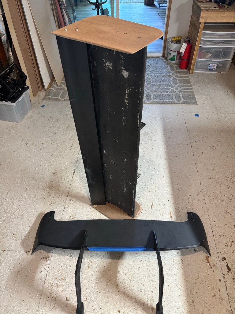
N wing – The N model came with a large chunk of plastic that is someone’s stylized idea of what a wing should look like. It doesn’t really have an airfoil shape, but let’s call it a wing since air goes underneath it, as well as over the top. In the wind tunnel it made 27.3 lbs of rear downforce and 3.5 lbs of front downforce at 100 mph.
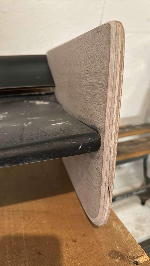
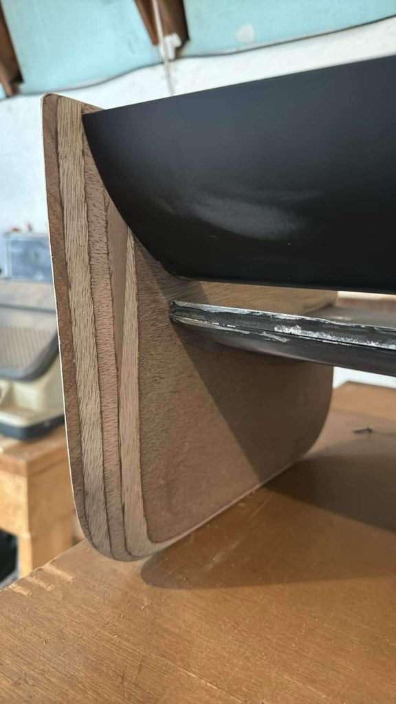
Ducktail – I tested a DIY ducktail spoiler in the wind tunnel, and it made over 140 lbs of downforce, but also a ton of drag. I felt it was too tall, and cut it lower. I don’t have wind tunnel data for the shorter version, but I’ll throw out a guess and say it makes 100 lbs of rear downforce and a couple pounds on the front.
Single-element wing – This is a DIY 54″x11″ S1223 wing with a small Gurney flap. I’ve tested it in the A2 wind tunnel and it made 113 lbs of rear downforce, but unlike the spoilers, it lost a little front downforce through leverage. The wing is located further rearwards and doesn’t aggregate high pressure on the roof, so the rear downforce gains are offset by front downforce losses; this is normal for all wings.
Dual-element wing – The above wing, but with a 4.7″ chord wing set at 30 degrees above the main wing. I didn’t test this in the wind tunnel, and I don’t have a good guess on downforce or drag, but it’s more of both.
N wing vs Ducktail
Take a look at the following speed trace, which shows the OEM wing vs the DIY ducktail spoiler. I started the session using the ducktail and after setting a decent lap, I quickly pitted, removed the ducktail, and replaced it with the N wing. This took about a minute, and I got right back out again and set a few more laps. The lap with the ducktail is blue, and the red lines are the N wing.
A – The first significant difference is a pair of left hand turns. You can see the blue line has a higher minimum speed in both of them, and results in a slightly faster top speed on the next straight.
B – These are two fast right handers, and again you can see there’s a significant difference in the minimum corner speed. On the following straight, the top speed ends up being the same, but on a longer straight, it’s likely the ducktail would slow down from drag. At this point in the lap, the ducktail has about a .7 second advantage, but over the rest of the lap where the corners are slower, there’s no difference.
Veloster N wing / spoiler.
Subjectively, I could tell the difference between the two rear aero devices. With the N wing, the car suddenly felt more lively, and the rear end moved around. This translated to more fun, but a slower lap time.
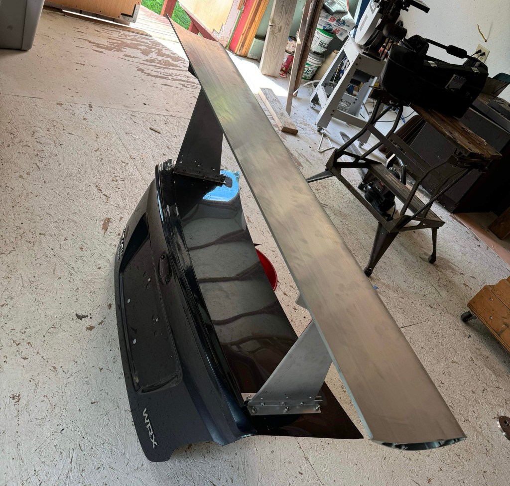
I have three different roof extensions for A/B testing. This allows me to switch aero quickly, and get back on track in less than a minute. The ducktail spoiler was used as the baseline for all other runs.
Ducktail vs single wing
Next I tried the ducktail vs the single wing, and they set nearly the same lap times. In the following speed trace, the ducktail is red, and the single wing is blue.
A – The long left-hand sweeper is pretty much the only place where the wing has an advantage over the ducktail, keeping a higher speed throughout.
B – The spoiler makes it easier to back up the corner, and I’m at full throttle earlier than when I use the wing.
C – Again, I back up the corner slightly better with the spoiler. It might be that the additional drag is helping me slow the car and get it turned earlier, but that’s just conjecture.
Single wing in action. Notice the tall end plates which are used to mount the upper wing of the dual element setup.
Subjectively, I couldn’t tell the difference between ducktail and wing. The wing was ultimately about .1 seconds faster, but I didn’t set enough laps to make that statistically accurate, and I’d call it a wash.
Ducktail vs double wing
Again I used the ducktail spoiler as the baseline aero, comparing the double wing to it. Since the single wing and ducktail were quite similar in performance, you could also say this is a single wing vs double wing test.
For this one I’m showing three laps from each, and I’ve also included lateral Gs, because there’s some additional interesting data points here. The ducktail is again red, and the double wing is in blue.
A – This is the long left where aero makes a difference, and you can see the blue lines in the upper graph are lower, indicating more lateral Gs. In the speed trace, you can see the difference is a couple mph.
B – What’s interesting here is that the lateral Gs at this spot are the same, but the vMin is higher for the blue line. Perhaps this means I have increased confidence in this corner, despite the same Gs?
C – The higher vMin in the previous corner allows me to consistently get to a higher speed.
D – The back straight is the only section where the ducktail is faster, and it’s entirely due to having less drag. You can clearly see the advantage in top speed.
E – Here the dual-element wing allows me to brake a little later, and that also results in a little time gained.
Double wing is double faster.
Subjectively, I can’t say I felt a huge difference between the spoiler and double wing, except that the double wing makes a small whistling sound at times. And on the back straight, I swore I could feel the drag from the double wing, but that could also be my imagination.
Conclusion
It’s pretty obvious from the lap times that adding rear aero makes this driver faster in this car. The Veloster has more rotation built in than the average FWD car (though maybe not as much as an Elantra N), and so it can benefit from additional rear grip at speed. It may also be that my particular driving style benefits from more rear grip. I didn’t do this experiment with another driver, so I don’t know if driving style is an important variable.
Caveats aside, the data shows that the double wing was about .6 seconds faster than the single wing or the ducktail spoiler. And both of those were about .7 seconds faster than the OEM wing. All said, I went 1.3 seconds faster using rear downforce alone, with no splitter or canards (although I do have hood vents, and I suppose that should count for something).
What’s surprising is that rear downforce made a quantifiable difference on a low speed track where aero only matters in a few corners. On a longer track with sustained high speed corners (Club Motorsports, Nelson Ledges, Palmer, etc.), I could see this being a three second advantage.
Another surprising thing I learned in this test is that I can make a minor change to the rear aero, and you can see it clearly in the 10hz GPS data. I know the track well and I’m a decent driver, but I make mistakes and I don’t have pro-level car control or consistency. So it doesn’t compute that there should be such an obvious signal in the data.
But I think what I’m seeing here is that I probably drive the car to the same level of instability. When the car is more settled, it allows me to release the brakes sooner and/or open the throttle earlier. And that flattens out mistakes I make from corner to corner.
So while I may not be able to drive the same line or make the same inputs exactly the same lap after lap, I end up driving consistently by maintaining a certain level of instability that I’m comfortable with. And that’s why you’re seeing strong signals in the data for what are relatively minor aero changes at low speed.
I would imagine that many other competent (but not professional) drivers do the same thing, driving to a certain level of comfortable instability. And because of that, I think using a 10hz GPS device to get long-G, lat-G, and a speed trace is acceptable data gathering for aerodynamic experiments.
I guess the final question is, why does adding rear aero alone reduce lap times? Mathematically, I’ve ruined the aerodynamic balance of the car by adding a lot of rear downforce and none in front. Engineers should be storming my house with pitchforks and torches, rooting out the madman who Frankensteined their masterpiece…. but for fuck’s sake, the car is actually faster. Either I need to do a bunch of math to calculate why that’s happening, or build an even bigger wing and fuggin send it. Yep.
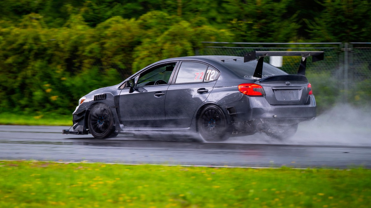
In the previous article, I mounted a Wing Logic wing to Steve Leo’s WRX. He’s been pretty happy with it, but I’ve been wondering about adding more rear downforce. An excess of rear downforce can make a car boring to drive, but it also improves braking, high-speed stability, and requires fewer corrections when you lose control. So while more rear downforce might ruin the aerodynamic balance, if the driver goes 2 seconds faster, let’s call that a better car.
If you want more downforce from a Wing Logic wing, you can increase the size of the Gurney flap by duct-taping down a piece of angle aluminum butted up against the built-in 1/4” Gurney flap. And with the larger wicker, you can add a little more wing angle. But you’ll soon hit a point of diminishing returns, and shortly after that, the wing will stall out. I haven’t run a full sweep on this wing, but I’ll guesstimate that a Gurney flap 1″ tall (very draggy) and an angle of attack around 11-12 degrees is the limit.
If you still need more downforce, the easiest way to do that is add a second element above the main wing, set somewhere between 25-35 degrees angle of attack (in relation to the main wing). Unlike the single wing, the double wing won’t stall because of the slot between the wings; Air shoots through the gap at great speed and this keeps air attached to the underside of the upper wing. Thus you can run more angle on the upper wing, which effectively increases both the chord and camber of the entire wing, without flow separation.
If you have a 9 Lives Racing wing, they can sell you a dual element wing for around $440 (with shipping). The kit includes the upper wing, plus adjustment brackets that go inside the standard end plate, plus little brackets that go in the Gurney flap slot. It’s a clever arrangement that’s easy to install and remove. I tested the double wing in a wind tunnel, and came away really impressed with how well it worked.
If you have a Wing Logic wing and you want a dual element, you’re shit out of luck. There isn’t a similar kit available, and I have yet to see anyone cobble something together. I wonder if the reason for that is because some people believe (incorrectly) that you can’t put a dual-element wing on top of a wing that has a Gurney flap? There was a recent discussion of this on the Professional Awesome Facebook group, and it seemed like most of the people said you should cut off the Gurney flap, or a dual wing won’t work with a Gurney flap on the lower wing, or that Gurney flaps only work on the top wing. That’s horseshit.
You can absolutely put a Gurney flap on the lower wing. Two research papers (James C Moss , and later F.M. Catalano and G. L. Brand) concluded that adding a Gurney flap to the main (bottom) element of a dual-element wing added downforce and improved L/D ratio. By fiddling with the Gurney flap height, overlap, and gap, they increased lift by 12% and increased L/D ratio by 40%.
But before you go adding a Gurney flap to your double wing, you should know that the authors only got those results after tons of experimentation. The height of the Gurney flap, the distance (gap) between the wings, and the overlap between the wings all need to be set correctly to get the most out of it. Knowing all of this, if you’re going to put an upper element on a Wing Logic wing (or any wing with a Gurney flap), you’ll need to be able to adjust the upper wing’s X-Y-Z coordinates for angle, gap, and overlap.
If this is all too much work for you, go and buy a 9 Lives Racing Big Wang and add The Deuce double element kit. It’s already set up with the right overlap and gap, and is simple to adjust for angle. The performance is excellent, and you will not be disappointed. Tell Johnny I said hi.
But if you’re a DIY-or-die kind of person (ahem, guilty), or you have more time than money, then maybe putting together your own dual wing how you want to spend a day. If that’s the case, read on and I’ll walk you through how I made a dual element for a Wing Logic.
Assembling the upper wing
I make wings rather than buy them, mostly so that I can experiment with different shaped airfoils and construction methods. My S1223 is a torsion box, and my MSHD is a foam core with fiberglass. But neither of those construction methods works great for a wing with a much smaller chord and less thickness. So rather than build one from scratch, I bought a couple cheap extruded aluminum wings on Amazon for $35 each. You can sometimes find them cheaper, and my friend Bill Fischer of Garage Heroes in Training once bought one of these wings and got a box of 10 for the same price.
Cheap extruded wing from Amazon, eBay, etc.
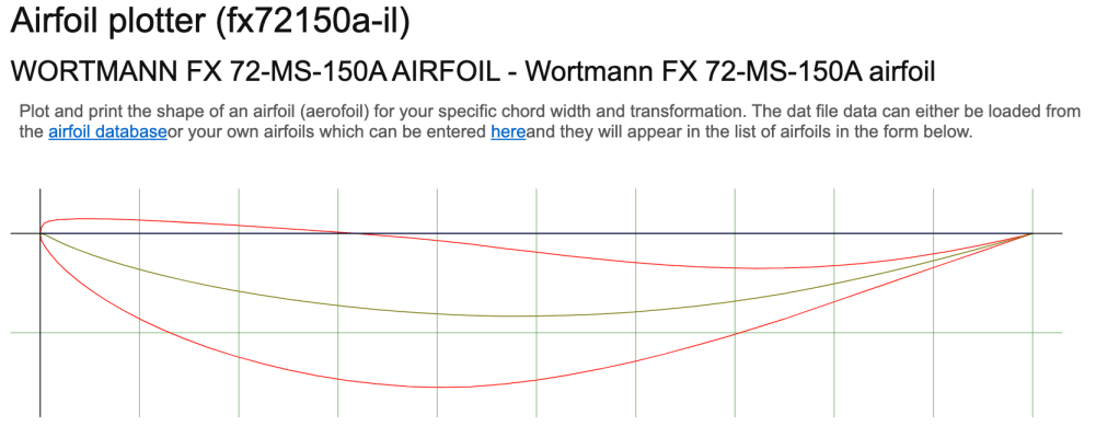
I’m not exactly sure what the airfoil is, but it looks a bit like a Wortmann FX 72-MS-150A. With a cL of 1.8, this is decent, but not what I’d call an ultra-high lift wing. According to my Car Wing Comparisons article, the airfoil outperforms the NASCAR used for in their Car of Tomorrow for a hot second.
Airfoil Tools is a great place to research wings.
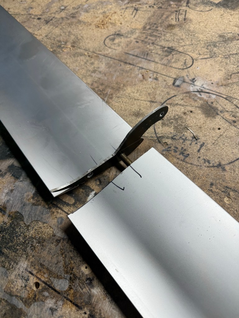
These cheap extruded aluminum wings are strong and light. They have two internal semi-circular spars that run the length of the wing, and provide a lot of stiffness. These supports are also tapped with M8 threads and do double duty fastening the end plates. While I might wish for a different shaped airfoil, the entire design is lightweight, sturdy, and inexpensive.
The wing has a 4.7” chord, which is larger than the upper element 9 Lives Racing uses. A rule of thumb is that the upper element should be about 30-40% the chord of the total wing (combined chord of main and second element), and this second element comes in at 32% of the combined 14.7”, and that’s right in the ballpark.
Wing profile and center support.
The longest of these cheapo wings I’ve found is 135cm (53.3”), and so if you want a bigger wing than that, you’re going to have to figure out a way to join them together. Welding is the obvious solution, but I didn’t want to rely on skin strength alone, I wanted to add an internal support as well.
M8 stud is threaded into both sides.
I cut threads into one of the wing holes and installed a M8 stud, bottoming it out on the threads. Then I tapped the same hole on the other wing. I sandwiched a little bracket between them, which will be used to hold up the center of the wing, and then twisted them upon each other, essentially threading the two wings together.
Both halves threaded together.
I took the wing to a local fabrication shop and they charged me their hourly minimum of $80 to weld it up. So that’s $150 for the upper wing, all in. I’m sure the welding could be done cheaper, especially if I was doing several wings at the same time.
Welded all the way around, and pivoting on the center support.
Double wing end plates
To mount the upper wing to the lower, I’d need to make new larger end plates that hold the ends of the upper wing. The top wing also needs to be able to adjust for angle, gap, and overlap, and because it fits inside the end plate, it’s kind of an end plate within an end plate situation. I made the inner plates from 9mm plywood because I needed to countersink the 8mm hardware into the ends. If I used 12 gauge aluminum, the bolt heads would stick up proud and keep the wing from changing angle.
Maximum angle for a second element is typically around 40 degrees, measured from the bottom element. But at this angle, the upper wing risks flow separation. A safer bet is to set the upper wing to 35 degrees, which should provide nearly the same downforce as the maximum angle of attack. I traced all this out on the end plate (a No Parking street sign, per my usual $1-per-pound source at the metal recycler).
I always lay out the chord line parallel to the upper edge of the end plate, this makes it easy to set the angle of the wing. I’m also mocking up the position of the upper wing.
I first made the maximum downforce 35-degree setting, and to this I added a low-drag setting of 25 degrees. I don’t see needing any more adjustment than that, because I can always rake the entire wing to adjust between the high- and low-downforce settings. If I want less downforce, I’ll just remove the upper wing and run it as a single. From there I can tune wing angle and Gurney flap height as I would any other single element wing.
Upper wing pivots inside of end plate. You can see the forward hole, which increases overlap and gap. The gaps are larger than you’d have normally, because of the Gurney flap.
The completed double wing weighs 22.8 lbs total, and so the upper wing added only 6.2 lbs, including all of the things required to mount it. That’s pretty light, and it feels quite sturdy. Eventually I’ll lighten the main wing by milling out slots and wrapping it with carbon fiber. But more on that DIY project when I’ve liberated the wing from Steve.
Completed wing.
Data?
This section is supposed to be filled with A/B testing data, including vital details about the ideal gap height for a dual-element wing that has a 1/4” Gurney flap on the bottom wing…. but instead it’s filled with a pissy rant.
Steve and I had a full test day planned, which involved him setting a few laps and then coming into the hot pits, where I could quickly change the main and upper wing angle, gap height, and swap between single vs dual wing. But despite an entire day at Watkins Glen, we got shit all of nothing. The problem is the same as the first time I did aero testing… Watkins Glen.
The weather is always variable, and the first session was wet and made data irrelevant. In the second session, a McLaren (620R?) dumped it’s coolant and oil on the first lap. This sent four cars into the T11 wall, and the cleanup crew onto the track for a lengthy stint. In the third session, again on the first flying lap, a Corvette stacked itself in Turn 2, requiring a full session of cleanup. And in the fourth and final run of the day, a BMW M2CS decided to get some new baby-blue racing stripes in T10. In the end, I don’t think the Advanced/Instructors run group got more than 15 minutes of track time the whole day.
Now this is the same run group I would have been in if I chose to drive that day. The two people I was with (Steve and Gregg) were the first two cars through the oil. Steve was going slowly because the McLaren directly in front was misting oil on his windshield. Gregg went through at speed and saved it like a hero. But he has a ton of experience at WGI and has proven many times over that he can save a spin.
Gregg saves it and avoids the wall. The next four cars don’t.
Well, if I was out there, I would have certainly been passing both of them in the session, which would have made me the first car through the oil. Dodged a bullet right there, I did! (I’m kidding about passing them; I drive like a grandma on this track.)
And this is why I seldom drive Watkins Glen, even for free. There are so many other tracks that have runoff, sand traps, and slower speeds, and are much safer as a result. Where I find enjoyment is pushing the car to the limit, and I’m not going to do that here, it just doesn’t make sense, financial or otherwise. My understanding is that some track day insurance companies will no longer cover cars at Watkins Glen, and I can’t blame them for that.
But I also understand that many of you like the combination of high speed and steel walls; you feel it gives you focus or commitment or whatever. Good for you. But the reason i have no data or wing gap information is because someone else also felt that way, and lost their focus or commitment or whatever.
Wing Logic makes a satisfactory wing at a great price. It doesn’t come set up for any particular car, and so you will need to do some DIY fabrication. You’ll have to figure out things like how to mount the wing securely in the correct location, and then you’ll need to drill the bottom mounts for a range of useful angles, and then weld the bottom mounts to the wing.
It takes some patience and know-how to figure it all out, and if I’m being honest, 90% of people will cock it up and do a sub-optimal job, losing some of the wing’s performance in the process. If you buy a ready-made kit from 9 Lives Racing, AJ Hartman Aero, and other reputable companies, you’ll get an easier install and better performance straight out of the box.
But if you know what you’re doing, a DIY wing like Wing Logic or 9 Lives Racing’s new Express kits, can save you some money. Or if you have a car that doesn’t have a ready-made kit available, then a DIY solution is the only game in town.
I tested a Wing Logic wing in the wind tunnel vs the industry standard 9 Lives Racing Big Wang (Wing Logic versus 9 Lives Racing), and found the performance was similar. Wing Logic’s wing has less camber, and so it makes less downforce for a given area, but it’s a physically larger wing (9.2” vs 10”), and so the performance ends up being quite close. 9 Lives has the edge in weight and performance, and so if you’re racing in a series that limits the total wing area (GLTC, SCCA TT Nats, etc), or if you care about two pounds (high up, at the polar end of the car), then 9 Lives is a better choice. For the track rat or hard-park poseur, it’s a wash. I have plans to radically lighten the wing by milling it out into a skeleton, and then wrapping with carbon fiber, but that experiment will have to wait until the end of the track season, because I no longer have it.
Steve Leo is making a foam composite dual element, and while that process takes place (for fucking forever) I loaned him my 65” Wing Logic for his Subaru WRX STi. He didn’t have any wing mounts for it, but he had a spare trunk, and I said bring it over and I’ll figure something out.
Because I had already tested this wing on a Miata, the wing has brackets welded 41” apart. Ergo, I’d need to put the same spacing on the Subaru trunk. As luck would have it, that put the wing mounts right on top of the hinges, which is a sturdy area with some extra thickness and support in the metal frame. Also as luck would have it, the hardware would now be in the way, and I’d have to work out how to allow the trunk to close.
But first things first, to place the wings on the surface of the trunk, such that the wing is braced against side to side movement. I went to the Lowe’s racing department and bought a couple feet of 1” angle aluminum. I cut this into four pieces to make brackets, and sandwiched the Miata wing stands between them.
But I couldn’t put bolts through the top of the trunk and nuts on the bottom, as the nuts would be in the trunk gutter – this would cause interference and keep the trunk from closing. So I installed the hardware upside down, with countersunk 6mm bolts going through the underside and nylock nuts on top. It’s maybe a little less attractive, but this was the only way I got it to work.
Countersunk bolts of differing lengths install from the bottom.
It took a bit of head scratching, but I figured out how to install all 12 bolts from underneath. It took bolts of different lengths, which I’ve noted in the previous images in case you want to give it a go. It all came out surprisingly sturdy, and probably more rigid than you’d see on most cars. You can grab the wing and shake the car side to side, and the wing mounts don’t move.
Angle aluminum brackets on the trunk hold the wing stands in place. It’s very rigid.
The only thing I wasn’t terribly happy with is that the wing is too far forward. The rule of thumb is to overlap the trunk by 1/4 of the chord. So on this 10” wing, 2.5” should overlap the trunk, and 7.5” should be over the bumper.
How important is that? Well, I tested a Civic coupe in the wind tunnel, and moving the wing from on top of the trunk to the ideal rearward position resulted in less drag and more downforce. Usually you get one at the expense of the other, but this was a win-win. I would have liked to do that for Steve, but I didn’t have any more aluminum stock to make another set of wing stands, and he needed this done ASAP.
We got super lucky with the setback distance, any closer and the wing would hit the roof when the trunk was fully opened. I’ll take that as a win and optimize the wing stands at some later date.
By a stroke of luck, the trunk can open fully and the wing doesn’t hit anything.
Data?
Steve reports that the wing is working really well, but through some bad luck, we have had the devil of a time getting comparative A/B data. He’s used the wing at Watkins Glen, Lime Rock, NYST, and Pineview Run, and while we have data from those events, it’s not the kind of back-to-back data that tells a compelling story.
By the seat of the pants, the Wing Logic setup works better than the VSC rally wing he had on there previously. But the Wing Logic single wing doesn’t work quite as well as the Wing Logic dual element he tried this week. Wait, what?! Dual-fucking-element Wing Logic? You can read about that in the next post.
I originally wrote this in 2024, but the 2025 classing rules have changed for both NASA and SCCA time trials classing. Changes below are in italics.
I’ve been thinking about taking my car to a time trial race, and as part of that, researching all of the time trials rules. But one thing that may throw a spanner into my plans is that I don’t want to turn any spanners myself. So if racing in time trials voids my warranty, I’m not racing.
But I have other options. If you’ve been following my blog, you know about Falconet, my Hayabusa-swapped Miata. It’s a serious race car that can do wheel to wheel or time trials. It will compete next year.
Anyway, as this is towards the end of the track season, I’ll ruminate on which series and classes my Veloster could compete in, if and when that happens.
NASA TT5
NASA time trials divides cars into classes by weight and horsepower. Power is averaged over a range of RPMs, so that peaky (low torque) motors have more parity with engines that have a broader spread of power. And there are modifiers for many things from aero to suspension to tire width. On paper, it’s all very fair, although some of the rules are questionable.
If I use the class calculator at 3200 lbs race weight, and specify that my car is FWD, has narrow tires, uses a splitter and wing, the car is allowed 256 average wheel horsepower. My car makes 244 peak horsepower at the wheels, and so you see it fits into the TT5 class with some room to spare (12 hp) for a cold-air intake and an exhaust. If I were to remove the splitter and wing, and use the base trim aero modifier (BTM), the car is allowed 275 average wheel horsepower. Since I’m not going to modify my engine, that puts my car 31 whp under the class maximum, and I’d have a hard time being competitive.
Now here’s the problem: TT5 has a maximum factory horsepower limit of 270 hp. So even though my car is 31 hp under the class limit, I can’t race in it! If I had the non-PP version of my Veloster N, at 250 crank hp, then I could tune the shit out of it, up to 275 at the wheels and be class legal. But my engine, which is 244 peak horsepower at the front wheels, is somehow illegal.
I’d like to see the logic behind this power cap in a lbs/hp series. Are they just trying to keep out the heavy cars? How does that even make sense in age when every new car is north of 3000 lbs?
Other cars that should be able to race in the TT5 class based on lbs/hp, but can’t because they have more than 270 hp, include the BMW 135i and 335i, Ford Mustang (EcoBoost), Dodge Challenger and Charger SXT, Hyundai Elantra N, Kia Stinger, Mitsubishi Lancer EVO, Nissan 350Z, Subaru WRX, and a slew of others. These aren’t popular track cars anyway, so who cares, right? And so instead of TT5 my Veloster N and the aforementioned cars all have to race in the next class up, TT4.
In 2025, NASA changed the maximum factory (crank) horsepower to 264 hp for AWD and RWD cars, and 275 for FWD. This makes the Veloster N legal, but the Elantra N isn’t, even though it’s heavier and ends up with the same power to weight ratio. While I don’t get the reasoning, I’d like to thank NASA for making my car legal for TT5, and also thinning out the competition. I may be racing with you sometime in the future!
If I’m going to nitpick the other rules, the other thing I don’t like is they don’t allow aero items from other classes. I mean… just use the point system you already developed, and instead of making canards, fender vents, diffusers, etc., illegal, make them cost points.
Grid Life
My Veloster can race in the Street class, which allows 4-cylinder turbos and 6-cylinder normally aspirated engines. Performance wise, there are some ringers in the class, but the Veloster isn’t that far off the pace. I wouldn’t be able to use any aero, or that would put me in Street Mod, which I could never be competitive in.
My Veloster also fits perfectly into GLTC, but that’s a wheel to wheel race class. However, COM has a GLTC-spec class in time trials, and I’ll get into that later.
In Canada, I could also race in Canadian Time Attack Challenge, which uses Grid Life’s rule set.
SCCA Time Trials Nationals
SCCA Time Trials Nationals (or is it Time Attack Challenge in 2025?) is moving their home track from National Corvette Museum to PittRace, and will hold the Nationals competition on Sept 18-21 2025. This is exciting for me, because PittRace is one of my favorite race tracks, and it’s a lot closer than NCM.
PittRace is awesome.
There are three classes I could race my Veloster in:
Max 3: This class allows a lot of aero, suspension, and engine tuning. I could use all of the aero I’ve built for my Veloster and race in this class, but for reasons I’ll explain in a minute, the car would be considerably down on power.
Tuner 3: This class has the suspension mods and engine tuning of the Max classes, but no aero mods. I won’t be racing in this class. (Side note, I feel like cars that are prepped to the Sport level should be able to use aero mods if they don’t take any other Tuner mods.)
Sport 3: This class allows minimal modifications, like lowering springs and intake/exhaust plumbing, but that’s it. It would be easy to prep for this class, but the Veloster isn’t at the higher end of the performance spectrum.
But that was in 2024, and now in 2025, instead of Max 3, Tuner 3, and Sport 3, my car goes into Max 4, Tuner 2, and Sport 3.
Max 3Max 4
I’m an aero guy, and so my first thought is to race in the Max classes because the Sport and Tuner classes don’t allow aero. The aero rules in Max are quite good and show a constant evolution, losing some of the silly restrictions (flat splitters) that the legacy rules had. Therefore, I could use all of the aero I’ve developed in the wind tunnel, without making more parts to a different rule set. Kudos to the TT rules makers for their willingness to adapt and change.
The Max classes use engine displacement to determine classing, and unmodified 4-cylinder turbos up to 2.46 liters go into Max 4. My 1998cc Veloster gives away displacement to engines like a 2.3 Ecoboost, resulting in a 75 hp deficit. So that puts me at a slight disadvantage to some turbo cars, but I shouldn’t complain, as 3-cylinder engines are only allowed 1.9 liters (?).
N/A engines are allowed up to 4.5 liters. In this category you have cars like the E92 BMW M3 and 718 Porsche Cayman GT4, both putting out 414 hp. That 140 hp deficit would be OK if my Veloster had a handling advantage, but these are pedigreed German sports cars I’m up against. Even worse, a 911 GT3 makes 500 hp from a naturally aspirated 4-liter flat six, and is in the same class as my Veloster. Grumble grumble.
This would also be in Max 2?
All said, if I want to be competitive, the Veloster doesn’t look like a great choice in Max 2. But I could also build the car with aero and not care about how I place, and do this race just for fun. That’s compelling, but also exactly what HPDE is for. Why enter a competition if you’re not going to be competitive?
Tuner 2
I never really considered the tuner classes, but I did notice a lot of cars moved from Tuner 3 to Tuner 2 in 2025, including the Veloster N.
Sport 3
Given that a stock-engined Veloster is way outclassed in Max 3, let’s see how it fares in Sport 3.
Unlike the Max classes which were based on displacement, the SCCA uses a list to determine which cars go in the Sport category. The rules say that the list of cars in each class is not based on a balance of performance, but on a “balance of popularity.” But I feel like that explanation is selling themselves short. The SCCA time trial board has done a great job of re-classing cars annually, and there’s better parity every year.
For example, the Acura NSX was originally classed in S2, but has been reclassed to S3, and is now considered an equal sparring partner to my Veloster N. The NSX is lighter and more powerful, but the 20-30 years between the cars may be significant. Other cars that moved from S2 to S3 include the Chrysler Crossfire (310 hp), Dodge Challenger R/T Scat Pack (470 hp), Kia Stinger (368 hp) Lexus GS-F (467 hp), and Nissan 370Z Nismo (350 hp). While all of these cars are more powerful than my Veloster, they are also heavier. Maybe it’s a fair fight?
370Z Nismo is in the same class as a Veloster N.
As of this writing, the following cars are in S3:
Acura Integra Type S 2024, NSX 1990-2005; Alfa Romeo Giulia Ti 2016+; Audi A3 2.0T All 2015-2018, S3 2013-2020, S3 Quattro Wagon 2006-2013, S4 2009-2016, S5 3.0T FSI 2008-2017, TT S 2009-2018; BMW 135i 2008-2013, M235i 2014-2016, 330i xDrive Sport Wagon 2017-2019, 335D 2004-2013, 335i All 2006-2013, 440i xDrive 2014-2020, 535i RWD 2004-2010, 650i Base 2005-2010, M3 2001-2006, M5 1998-2003, Z4 Coupe M 2006-2008, Z4 35i M 2009-2016, Z4 35is M 2009-2016; Cadillac ATS 3.6L V6 2013-2015, CTS V 2004-2007, CT4 V 2022; Chevrolet Camaro SS 1998-2002, Corvette Z07 1984-1991, Corvette Base 1984-1997, Corvette Non-Z06 1997-2005, SS 2014-2017; Chrysler Crossfire SRT6 2004-2008, Dodge Challenger R/T Scat Pack 2015-2022; Ford Focus RS 2016-2018, Mustang Ecoboost 2015-2023, Mustang GT 2011-2014, Taurus SHO 2010-2018; Genesis G70 3.3T 2019-2022; Honda Civic Type R 2016 +; Hyundai Elantra N 2022, Genesis R-Spec (All) 2013-2016, Veloster N 2019-2022; Kia K5 GT 2021-2023, Stinger GT 2018-2023, Stinger GT2 2018-2023; Lexus GS-F 2016-2020, GS350 FSport 2016-2020; Lotus Evora Base – NA 2010-2014; Mercedes C450 AMG 4MATIC 2015-2016, C55 AMG 2004-2007, CLK55, AMG 2003-2006, SL550 All 2007-2013, SLK55 AMG 2005-2011; Mitsubishi Evo All; Nissan 370Z Nismo 2009-2013; Polestar 2 Dual Motor, Performance Pack 2020-2024; Pontiac Firebird Firehawk/Formula/Trans Am 1998-2002, GTO 2004-2006; Porsche Boxster S 2005-2012, Cayman S 2005-2012, Cayman Base 2009-2012, Cayman Base 2014-2016, 911 Carrera 2, 2S, 4, 4S 1999-2008; Subaru WRX ALL 2009-2021, WRX STI All; Toyota Supra GR 2.0 2021-Current, Corolla GR 2023-Current; Volkswagen Golf R 2015-2021; Volvo V60 Polestar 2016-2018
I’m not super interested in what the SCCA thinks about a balance of popularity, what I really want to know is, how do these all compare in performance? Hello COM.
COM
Corvette Owners of Massachusetts (COM) has perhaps the fairest time trials rules in existence. They calculate a car’s performance using the weight of the car divided by its power and then factor in a Performance Adjustment (handling).
To calculate power, COM uses an average of horsepower and torque, which is smart because the torque curve is hugely important. COM then modifies the power-to-weight score using Performance Adjustment points that range from -25 to +28.5. This factor takes into account things like suspension, brakes, tire width, aero, etc. Those two numbers are added together, resulting in a Showroom Assessment score, and from this the cars are placed in classes ranging from T30 (the slowest) to T110 (the fastest.)
The Veloster N is listed at 71.7 points, at the bottom of class T70. I could compete fairly in COM taking modifiers to aero or tires and come right in at the class limit.
But the other thing COM is great for is comparing the relative performance of different cars. And so I did that for all of the cars on the SCCA Sport 3 list, and the average is 72.5 points. So on first blush, it looks like the Veloster is right in the middle of the performance range.
However, there are a lot cars that are ranked higher, including the aforementioned Nissan 370Z Nismo, several BMWs (E46 M3, 135is, M235i, and Z4M), and every generation of Mitsubishi Lancer EVO or Subaru WRX STi. Given that every one of these has a better power to weight ratio, and that they are AWD or RWD vs the Veloster’s FWD… I have to think I’d be on the back foot against them. But I also feel like I’m a decent driver and my car is close enough in performance that I’m up to the challenge.
But there are even faster cars in Sport 3, and at the pointy end of the class are several cars that COM puts in T80, meaning they have more than 80 points. Among these is the Veloster’s nemesis, the CTR.
FK8 CTR is a class favorite.
When the Veloster N came out, it was regularly pitted in comparison tests against the Honda Civic Type R (80.2 COM points). The CTR beat the VN every time, but it was close. In the comparisons, many YouTubers would choose the Veloster for the fun to drive aspect, but the fastest lap times were all owned by the Civic.
Some of the Type R advantage is Honda power, with +31 hp and +35 torque out of the same displacement. But COM also rates the Performance factor at 8.3 vs 7.5 points. So not only does the CTR out power the VN, it out handles it as well.
Which I find surprising because I think the Veloster is the best handling FWD car I’ve driven. Admittedly, I haven’t driven a Civic Type R, but I think the Performance Adjustment discrepancy comes down to the size of the wheels and tires. The Veloster comes stock with 8″ wide wheels, and 8.5” is about as wide as you can fit. Ergo, most people are using a 235 width tire.
Conversely, the Civic Type R comes stock with 9.5″ wheels, and you can go wider still. So it’s quite possible to fit 265 tires on a CTR, and maybe even go all the way to the class maximum of 285? The Elantra N isn’t on the COM list as of this writing, but like the CTR, it has more power and wider tires than a Veloster.
But my competition doesn’t end there, the overdogs in the S3 class are the 987.2 Cayman (80.4 points), 992 Carrera (82.3), Ford Focus RS (82.5) and non-Z06 C5 Corvettes (83.1). These T80 cars are higher performance than anything else on the Sport 3 list, and might even stomp a CTR.
S3 overdog would be a full class higher in COM rules.
So even if my Veloster N is in the middle of the COM performance window for SCCA’s Sport 3 class, it’s likely that a majority of the cars will have a better power-to-weight ratio, and significantly wider tires. The question is, can a 275 hp FWD hatchback on 235 tires beat a 350 hp RWD on 285 tires or 350 hp AWD on 265 tires? To find out, let’s see some historical results.
Sport 3 lap times
SCCA TT lists the results for every race, and after dumping them all into a spreadsheet (and correcting the fact that they don’t put the fields in the same place each time), I got an idea of which cars are the fastest and most popular in Sport 3.
At the top of the list is the FK8 Honda Civic Type R, with seven wins and lots of podiums. The next most popular is the 2017+ Camaro SS with five wins. After that you have a pair of German sportscars, the Porsche Cayman and BMW E46 M3, with four wins apiece. The Ford Focus RS is the first of the AWD cars and nets three wins, and then you have a contrast of early Porsche 911 vs modern Ecoboost Mustang with a pair of wins each. Finally there’s a smattering of cars with just one win, such as a 2014 Cadillac CTS, 2012 Audi TT, 2022 GR86, 2006 350z, 2015 M235i, and finally a 2021 Veloster N. Which is especially poignant because it won the 2021 Sport 3 class at PittRace.
PittRace lap times
SCCA Time Trials has been to PittRace a couple times, and looking at the results, it appears that I should be aiming for a 2:05 lap if I want to be the fastest ever Veloster, or a high 2:02 if I want the fastest all-time S3 lap (yeah, right). I’m sure that people will up their game for Nationals, and so I don’t doubt that someone will make a new lap record, weather permitting, but can someone go under the 2:00 minute mark?
Year
Driver
Car
Lap
2019
Thomas Edward Philipps
2018 Civic
2:02.997
2021
James Avellina
2021 Veloster
2:05.397
2021
Shelly Avellina
2021 Veloster
2:06.767
2019
Randall Prince
2017 Camaro
2:08.580
2019
Fausto Sarmiento
2016 M235i
2:10.817
2019
Jared Romanyak
2009 370Z
2:12.012
2022
Christopher Schimmel
2009 370Z
2:12.190
I also looked at the Tuner 3 lap times at PittRace, and most are a couple seconds faster, with one car going under 2 minutes. Meanwhile, two FK8 Civics did 1:58s in Max 3. So the delta between Sport 3 and Tuner 3 is a little over two seconds, which is about the same gap between Tuner 3 and Max 3. Comparing Sport 3 and Max 3, I would need over 4 seconds from aero to make my Veloster competitive in Max 3, and I have a hard time seeing that happening.
Racing and Sim racing
I’ve raced at PittRace a few times in 24 Hours of Lemons and Champcar, and I’m slated to race a B-Spec Honda Fit this year with the Garage Heroes in Training. The event is is a Lucky Dog endurance race, and so with no mechanicals or mishaps, I’ll get a decent amount of track time. Which is important, because by next year, I need to know PittRace like the back of my hand.
To that end, I’m also doing some sim racing. My brother Ian (yousuckatracing) set me up with a sim rig, and I do a few laps every morning. I’ve been playing Gran Turismo since GT came out, but with a controller, and so it’s taking me a while to get the feel of a wheel and pedals. I’m currently only racing Assetto Corsa, because it has the PittRace track. A lot of my friends seem to be on iRacing, but that costs money and doesn’t have PittRace, so….
I’m just getting started sim racing, so I’m not too proud of these times, but in the spirit of transparency and learning from others, this is where I’m at:
Car
Tires
Lap
Miata NA
Street
2:17.9
Alfa Mito
Semi-slick
2:07.8
GT86
Street
2:09.0
Giulietta QV
Street
2:08.2
Audi S1 +200kg
Semi-slick
2:07.8
Abarth 500 s1
Semi-slick
2:07.8
GT86
Semi-slick
2:07.6
Miata ND1
Semi-slick
2:07.6
Audi S1
Semi-slick
2:05.5
370Z
Semi-slick
2:01.0
Unfortunately I don’t have a car that approximates at Veloster N, but Ian is good at modding things, so I’ll get him to make me one eventually.
Flow separation is the enemy, and is to be avoided at all costs. One of the main culprits of flow separation is a sharp leading edge, which can cause a separation bubble behind it, and results in downstream turbulence, increased drag, and loss of downforce.
Where I see sharp leading edges most often is on splitters, and oddly, the more expensive the splitter, the more like it is to have a sharp leading edge. Shitty plywood splitters are blunt to begin with, and usually get rounded over by their owners, either intentionally or through use. On the other hand, Alumalite and carbon splitters usually have a sharp edge, and the manufacturer (or DIY-er) does nothing about it.
Which is fine when conditions are perfect and air hits it directly head on. However, when a car pitches forward or backward due to acceleration and braking, or when the splitter blade is heaving up and down due to suspension movement, or you’re drafting a car in front of you and in its wake, then the air hits the splitter at an angle. In these situations the flow separates on one side or the other, and you get downstream losses.
Take a look at the following drawing. Air is coming from the left and hitting the nose of the car. In each case, the splitter is dividing the air into two halves, one that goes above the blade, and one that goes below. Let’s take a look at how this changes with air hitting the front at an angle, and with the shape and thickness of the leading edge.
Splitter leading edges.
A. This represents the best case for a splitter with a sharp leading edge; air hits evenly at the front and splits evenly around. This is also known as fantasy land.
B. This represents a car that is pitching due to acceleration, hitting a bump, cresting a hill, following another car, or really any other situation that makes air hit the front of the splitter at a slight angle. In this case the air separates at the leading edge, losing laminar flow, creating a separation bubble behind it, and causing downstream turbulence. Further downstream, the air might reorganize again, but the downforce you are trying to achieve is gone, and instead you got drag in its place. That carbon splitter may have cost you a pot of gold, but in exchange you got a bag full of shit.
C. This is the same splitter and air angle, but the top of the splitter has been thickened and rounded at the leading edge. Air now flows around the underside, staying attached the whole time. The top side may get a small separation bubble depending on the angle, but the pressure side of the blade is of little consequence.
D. This time the splitter lip is thickened and rounded on the underside, and the effect is similar to C, but not quite as good. The problem is this may cause ground clearance issues, which would require you to reset the height of your splitter. Also, if you race in a series that requires a flat or horizontal splitter blade, you no longer have one. You’ve also created a shape that may have an adverse pressure gradient where the thicker lip meets the flat splitter; when curving a splitter, the curve is usually an arc that goes the other way.
Conclusion
My best inspiration for splitters comes from wings. Take a look at the leading edge, they are always thick and well rounded on the underside (or top side for an airplane), because wings work through suction.
The same is true for wing mounts. Swan neck wing mounts are optimized for the underside. By placing the brackets on the less important pressure side of the wing, the suction side is left undisturbed, which results in lower drag and increased downforce.
And it’s the same for splitters; we don’t care too much about the air that goes on top of the blade, as this is the pressure side of the splitter. Air on the pressure side can be a bit disorganized and it still works fine. We care a lot about the underside of the splitter, because this is the suction side, and any turbulence or flow separation here has massive consequences.
Splitters need to be optimized for the underside of the blade, and this begins with the leading edge. A thick and well rounded leading edge allows air to stay attached at varying angles of attack, and keeps flow laminar along the surface. If you have a sharp leading edge, add some material (plywood, 3D printed plastic, foam/fiberglass, etc), so you can thicken and round it. This will add some rigidity as well.
Peter Liu’s 3D printed splitter lip fixes the sharp leading edge problem.
If you have modified a sharp splitter blade, send me a picture and I’ll add it here to inspire others.
A proper leading edge. Thanks Peter Liu.
[Update 10/16] Shane Wilcox had the typical splitter with a sharp leading edge and sent me an email asking what he could do? I sent him to Peter and he got a 3D lip on the leading edge. The change was nothing short of dramatic.
The increased downforce ripped off the lightweight bumper, and required a heavier OEM and additional splitter rods to avoid dragging. Once that was solved the car had so much downforce it started to oversteer. Well, I can’t wait to see what happens when Shane addresses that with more rear downforce, lap times be falling!
James Mewett also thickened and rounded his front splitter lip, and took the following picture.
This picture says so much.
It’s illuminating to see how the path of air is influenced, so far above and ahead of the splitter. Since the underside of the splitter does the most work, this modification should work really well.
I love I hear success stories like these, so if you’ve fixed your splitter lip (or used any other tips and tricks on this website), contact me and I’ll write up a testimonial.