Blog

Aero vs BTM in NASA ST6/TT6

I was chatting with a guy on Facebook the other day, he does time trials in NASA TT6, and was wondering about gearing ratios. I ran a couple simulations for him in OptimumLap with different gearing. It wasn’t very much different, shorter gearing was a hair faster, but required more shifts, which OptimumLap doesn’t account for. In the end we got to conversing about ST6/TT6 Miatas and whatnot.

The NASA ST/TT series is a really cool system based on power-to-weight ratio, which is then further modified by your car and its mods. For example, a Miata has A-arm suspension, and must take a -0.7 penalty to the power-to-weight ratio because that’s an advantage of cars that have Macpherson struts or whatever else.

Aero is another place where points are assessed, and if your car has stock bodywork, then you get a bump in power-to-weight ratio. They call this BTM aero, which means Base Trim Model, or in this case, Boring Typical Miata. You get a bit more horsepower if you run your car with stock bodywork. Here’s a brief look at the aero modifiers, and how they affect power to weight.

  • +0.4: BTM aero (more power for stock aero)
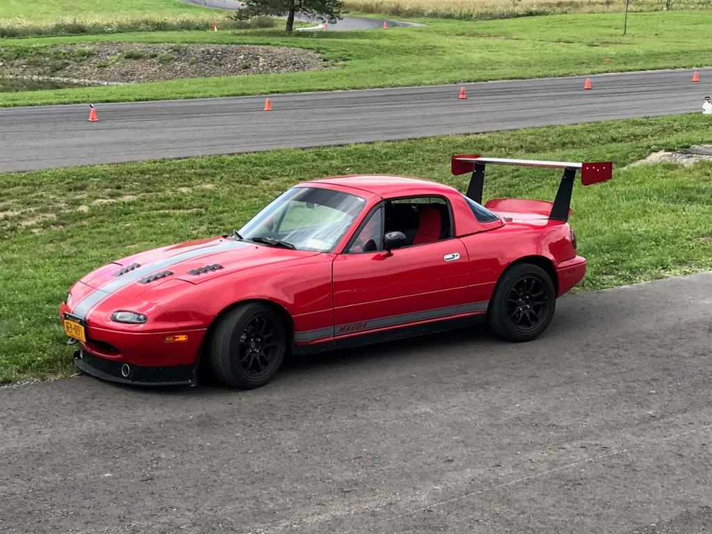
  • 0: Non-stock aero (R-package lip, airdam, etc)
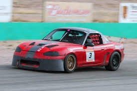
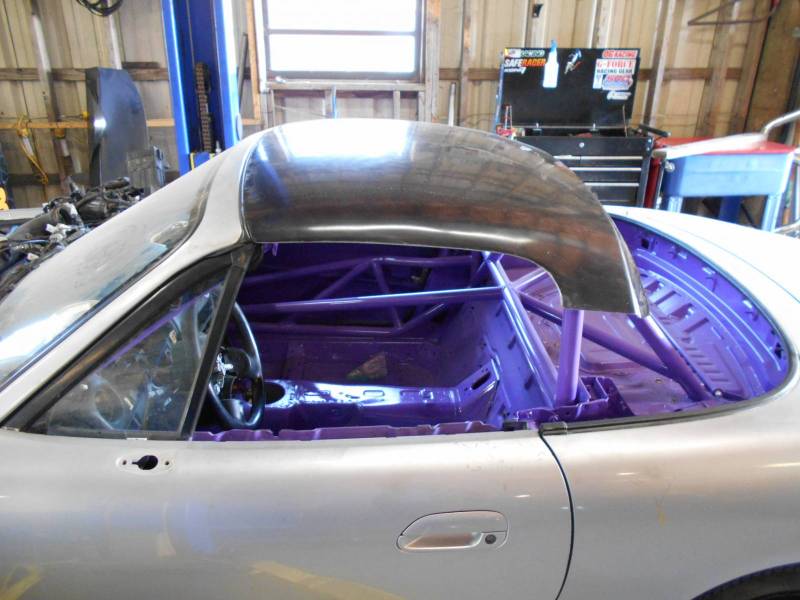
  • -0.4: Altered roofline shape (fastback, Chop Top, etc)
  • -0.4: No windshield (and by that, no roof)
  • -1.0: Wing or spoiler (a big HP penalty for rear aero)

The guy I was chatting with on FB told me that at a recent race there were 11 Miatas in ST6 and/or TT6 and every one of them was running BTM aero. I was kind of surprised by that, because Miatas have shitty aero, and it’s a lot easier to tack on an airdam than it is to add a bunch of power.

Image result for spec miata
BTM aero = slight bump in HP.

Maybe some of them were NBs? NB Miatas had better aero than NA, and I suppose if you have a NB, then BTM might be the way to go. I don’t have drag and lift data for NBs, so I can’t compare. But on a NA Miata, you’d have to think at least an airdam would help.

Image result for NA miata airdam
An airdam would decrease drag and lift, and would get a HP penalty.

So I ran some configurations in OptimumLap, using 2460 lbs and adjusted horsepower to the class limit based on different aero modifiers. I used Watkins Glen and Summit Point (main) for the two tracks.

Here’s a brief description of each car configuration:

  • BTM – Stock NA aero. I’m using .5 and .55 for drag and lift, which are close estimates based on my testing. This version of the car has the fewest penalty points, and ergo the most power, at 131.6.
  • Airdam – .45 drag and .5 lift are pretty accurate numbers. People may wonder why they are so high, it’s the open windows that destroys aero. The airdam loses the BTM modifier, so HP drops to 128.8.
  • Airdam + Chop Top – Treasure Coast’s “Chop Top” had the best L/D ratios of all the tops when used without a wing. It didn’t work well with a wing, so we won’t bother with that configuration. It’s unclear if this would be penalized for changing the roofline shape, so I took the penalty and HP is 126.2. But it would have 128.8 HP if it’s considered standard roofline shape.
  • Airdam and fastback (AD/FB) – A sleek combination with the lowest drag of .38, as verified in testing, and a lift of -.35. The roofline modifier of -.4 means this has only 126.2 HP. Note that a fastback in ST/TT6 couldn’t extend all the way to the rear of the car, the rules state that the roofline must terminate at the front edge of the trunk. So the fastback shape would be more of a Kamm-back. I don’t think it would perform as well as a true fastback, but I’ll just leave the numbers alone for now.
  • Airdam and wing (AD/Wing) – Using a wing in ST6 is a full 1-point penalty, and brings HP down to 122.4. May as well run the airdam because you’re no longer using BTM aero. The Cd and Cl figure here is based on my tests with splitter on and off. Taking the splitter off reduced downforce by .38 and increased drag by .01.
  • Airdam, fastback, wing (AD/FB/Wing) – Using all the aero at once is the largest penalty, and gives an even 120 HP, 11.6 less than BTM aero.
ConfigBTMAirdamAD/CTAD/FBAD/WingAD/FB/Wing
Total Points-.7-1.1-1.5-1.5-2.1-2.5
HP131.6128.8126.2126.2122.4120.0
Cd, Cl.5, -.55.45, -.5.48, -.31.38, -.35.49, .63.42, .82
WGI140.89140.31140.61139.03138.42136.98
Summit84.0883.7983.7583.0881.8481.02

As you can see, at both Watkins Glen and Summit Point, aero beats power in a simulation. And possibly in a time trial where there’s no traffic. However, in a real-world race, you might choose power, thinking it’ll be easier to pass a slower car that’s holding you up.

Another thing to note is that while the versions with the wing went the fastest, it might be hard to balance that much rear downforce with nothing up front. Splitters aren’t allowed in ST6/TT6, and the front aero load distribution would be pretty light. So while the simulation says the wing is faster, in the real world, it might not be. You also have to factor in that a wing adds about 20 lbs high up and at the far end of the car, and I can’t calculate what that would do in OptimumLap. In the real world, mass centralization is a valuable thing.

All said, I think the airdam/fastback combination looks pretty good, it’s a full second faster than BTM aero at Summit Point, and 1.8 seconds faster at Watkins Glen. The Chop Top also does pretty well.

Another reason to choose aero over BTM is maybe your car makes 120-odd horsepower and you don’t want to shell out for the engine mods that would be required to hit the class limit. In this case, aero could be a cheaper way to run faster lap times.

A note on these simulations: I used a 7500 rpm redline (I forgot to change it to 7000 and ran all of them at my redline), and 4.1 final drive, with tires that grip at 1.3g. I don’t run Hoosiers (or whatever), and lack that data. So if the lap times at these tracks are not super close to real world, that’s partly why. The comparative differences between the configurations is the point.

Part 2: Static HP

I posted the results of this blog on the Miata Race Prep group and got some interesting replies and requests to run more simulations.

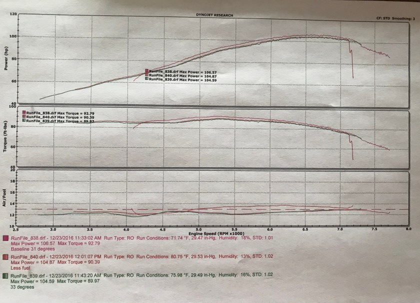
Dan Howard suggested I keep the HP static and adjust the weight. This is because 130+ HP is pretty unrealistic in a NA Miata, and that’s a good point. So I’ll reduce HP to 114 (which is about what my 1.6 makes these days) and re-run the data and adjust the weight. I’ll remove the Chop Top from the comparison this time.

Note that this makes the BTM aero version very light, and slightly below 2150 lbs. That should incur another -0.1 penalty, but I’ll cheat a bit in favor of BTM because it lost last time. Also, if the full aero package added just 2 lbs, it could get a slight 0.1 bump in power. But it’s winning, so we’ll leave the playing field level.

ConfigBTMAirdamAD/FBAD/WingAD/FB/Wing
Total Points-.8-1.2-1.6-2.2-2.6
Weight21432189223423032348
Cd, Cl.5, -.55.45, -.5.38, -.35.49, .63.42, .82
WGI142.12141.26139.68138.73137.05
Summit84.6384.1883.3082.0081.07

If you compare the times to the previous table, you’ll see the same relationship, with aero winning out over power. In addition, notice that lap times are overall a bit slower, because reducing weight isn’t as effective as increasing power in OptimumLap.

I’m not sure what the deal with that is, because in the real world, I notice about a .8 second difference in lap times at Pineview Run with a 200 lb passenger. If I do a simulation in OptimumLap and add 200 lbs, it’s only a difference of .33 seconds. So for whatever reason, OptimumLap simulations don’t make weight as consequential as power, even if the car has the same lbs/hp ratio. Anyway, it’s a fucking simulation, and I wouldn’t bet a race on it.

Part 3: Spoiler and Airdam

Damn the power or weight, the winning aero simulation so far has been with a fastback and a wing! But it’s pretty clear that it would be hard to balance all of that rear downforce without a splitter. So what about using a smaller wing, or a wing with less angle of attack? That makes sense, but I don’t have that data. But I have some spoiler data, and that would balance an airdam nicely.

The data I have is from some back-to-back tests I did, and based on some pretty tight lap times, the spoiler made a difference of .55 seconds, which I calculated as .45 in coefficient of lift. This is me driving, and naturally there’s noise in this data, but whatever. I found that number pretty shocking, but a graph in Race Car Aerodynamics has similar results, and so maybe it’s accurate. Accurate enough for a simulation, anyway.

For this configuration, I’ll use a Cd of .46 and a Cl of -0.1 I’ll use the de-powered 114 hp Miata from Part 2, which means the car weighs 2348 lbs.

  • WGI: 140.96 (BTM 142:12)
  • Summit: 83.67 (BTM 84.63)

If the real world is like the simulation, then the airdam/spoiler package is about a second faster than BTM aero at both tracks. The spoiler also beats the airdam alone, which surprises me, because the spoiler costs a full point, the same as a wing, and this incurs a large weight penalty.

Autocross. I don’t F@%#king get it.

I recently went to my country club, Pineview Run, to do some low-speed aero testing. I didn’t check the schedule ahead of time. My bad, the track was rented out to an SCCA autocross group. Todd said I could run when the autocross was finished, so I sat around and watched for a few hours.

Lots of neat cars, including a Miata with no windshield and aluminum panels screwed down over the passenger compartment. It was on slicks and looked like a shitload of fun. There were a lot of other neat cars, as well, and it was great to see the parking lot full!

Image may contain: car and outdoor
Neat cars come to autocross.

Pineview limits entries to 50 cars, and these were split into two groups of 25. They don’t use the whole track. Instead, they grid the cars on the front straight and do a timed run from a standing start near Turn 2. The timing ends before the final corner, and then the car goes back to its grid spot on the front straight, ready for another run.

Pineview pro driver Takis was the fastest, and completed the course in 50 seconds. He’s a regular at Pineview, and is capable of 1:10s, so that means there’s about 30% of the track that isn’t being used. On some sections of the course, they also put cones up. Why? It’s not a parking lot, it’s a short and twisty track that already has corners. Is it not an autocross without cones? Or is it that every autocross requires a dumb slalom section? Whatever the case, I don’t get the need to place (and thereby replace) cones on a track like this.

Enough of the cone rant, let’s do some math. The fastest car was doing around 50 seconds, and the slower cars were doing over 70 seconds. If the average car takes a minute to circulate the track, and they let out the next car say 10 seconds later, that’s 70 seconds per car. Multiply that by 25 cars on grid and each car gets a run about every 30 minutes. That group of 25 had to swap with another group of 25 who were all waiting in the parking lot. So there’s a shit ton of waiting in the parking lot, and even when you’re on grid, you have 30 minutes between runs. Are you fucking kidding me?

Well at least it isn’t very expensive. For SCCA members, it’s only $50, so maybe that’s the appeal? But again, let’s do the math. Based on track time, they are getting maybe six laps per day, so that’s about six minutes of track time, or $500 per hour. That’s ridiculous. Pineview recently ran a $129 open track, which is about an hour and a half of track time per car. So autocross is 6x more expensive than a track day?! For realz?

I saw a lot of talking and comparing of notes, it’s definitely a talker’s sport. And there is some degree of competition, I suppose. I guess that’s why people do it? But it seems like a total fucking waste of time and I wouldn’t wait around for 30 minutes to take one lap that I couldn’t even string together with another lap.

It would be a lot more efficient to let them do a couple laps at a time. Heck, space the cars out and get more cars on track at once. Oh wait, that’s what the Pineview Challenge Cup is. That makes too much sense for this group.

Pick up your cones so I can get on track!

After the autocross suckers packed up and left I got to run as many laps as I wanted, with no run groups. I went out, did a few laps, came in and adjusted the wing. Went out, did some more laps, removed the splitter. Went out, did some more laps, removed the wing. Etcetera. In the time it took for one of the autorcrossers to wait for another run, I’d done twice as many laps as they’d done all day. And I was stopping every few laps to make adjustments!

I don’t get autocross. I have race team members that do it, they’ll have to explain it to me sometime. I think one of them said he likes picking up cones.

Modifying a Spec Miata for Endurance Racing

Alyssa and I were working on my car this weekend, and, surprise, we started talking about racing Miatas. We see a lot of Spec Miatas converted to endurance racing, and we discussed what different options to power, weight, grip, and aero would do in a 24-hour race.

So we imagined a fantasy team that started with a 1.6 Spec Miata, which they wanted to improve for endurance racing. Since this is fantasy game, let’s pick a silly fantasy name like Hugh Jass Racing. And give them a web page, and channels on twitch and youtube.

IMG_0691 Tom (1).jpg

Here are their current options, with the data necessary to run these simulations in OptimumLap.

  • Stock: This is their car as is. OEM hard top, stock bodywork, lowered suspension, 2300 lbs, dynoed at 120 hp, 4.3 final drive. .45 Cd, -.45 Cl. The drag and lift might be more than this, I’m being kind.
  • Light: Drop 200 lbs.
  • Power: Swap in a 1.8, 140 hp.
  • Grip: Like most Spec Miatas, this team has 15×7 wheels. This option simulates changing grip from 1.1g to 1.2g. This could be 205 RE71Rs on 15x8s, or some other cheaty 200 TW tire. If you don’t think there’s a difference in wheel width, go to the GRM Summer Tire Test and you’ll see the Z3s picked up 8/10ths of a second on a 33-second course by going from 7″ to 8″. (But still half a second behind the RE71R on 8″.)
  • Aero: Add an airdam, 4″ splitter, and 9LR wing. This changes the Cd to .48 and the Cl to 1.01, and adds 40 lbs.

I ran this simulation at VIR. After adding the car data in OptimumLap, I corrected the grip to 105% to get lap times that are about what Alyssa runs at VIR when the track is clear, and his knowledge of what other teams typically run on similar setups. We also cross listed top speed in OptimumLap with real-world GPS data, and were spot on.

I made this a 24 hour race, with 100 minutes subtracted for yellow flags, and 5 minutes for each pit stop. Here’s how the car options pan out.

ConfigurationLap TimeTotal Laps
Stock2:23.63538.8
Light2:22.40543.5
Power2:20.43549.0
Grip2:20.42551.2
Aero2:20.67551.2

The first thing that strikes me about this data is how boring it is! Adding power, grip, or aero are almost identical in this simulation. Each are equal to about 3 seconds per lap. At the end of the day, the Grip and Aero versions turn exactly 551.2 laps, and beat the Power version by two laps (only because the 1.8 consumes more fuel). However, in the real world, you might choose power, because it’s easier to get around cars that are running a similar speed and slowing you down. If I increase the gas tank size or reduce stints to 90 minutes (AER), then power wins by a smidge.

Lighter is always better, and removing 200 lbs beats the as-is car by 5 laps. But that wasn’t nearly enough to match the other options. In order to do that, I’d have remove 500 lbs. At 1800 lbs, the car completes 550 laps, but really, who can get a Miata that light with a driver? As an aside, removing 100 lbs was a difference of .62 seconds per lap, which is about the difference between a light driver (Alyssa) and heavy driver (normal people).

Supermiata in the mix

Supermiatas have a good combination of power, grip, and aero. The spec formula is an airdam without a splitter, a spoiler, 2400 lbs, and 140 hp. How would that fare against these other options? Let’s find out.

Image result for supermiata

I don’t have data on the exact aero combination, but this is just for fun, so I’ll estimate a Cd of .45 and a Cl of zero. That’s a .45 shift in coefficient of lift due to the airdam and spoiler, which is ballpark-ish. I’ll use 1.2g of grip, because they run on 15×9 wheels instead of the skinny 15×7 Spec Miatas use. I’ll do two runs, the second one adding a splitter, which my tests showed increased downforce by 0.38 and reduced drag by .01.

ConfigurationLap TimeTotal Laps
Supermiata2:16.29563.5
Supermiata, 4″ splitter2:15.08568.5

The Supermiata build wins by a lot because it has all three: power, grip, and aero. So that was a little unfair, so let’s see what happens when we combine options for the fantasy team.

Pick two. Which two?

The fantasy team has the budget to afford power, grip, and aero, but in the real world, you might have to choose two. But which two make the most sense? I’ll drop the lightweight version since it wasn’t competitive, and see which two options make the best combination.

ConfigurationLap TimeTotal Laps
Power, Grip2:17.09560.2
Power, Aero2:16.85561.2
Grip, Aero2:17.66560.1
Power, Grip, Aero2:13.81573.9

If you have to choose two, the combination of power and aero wins by one lap. If you live in fantasyland and can have all three, you win by a lot. And you even spank the Supermiata.

One thing to notice is that these options are not directly additive. If you add up the benefit of power, grip, and aero individually, it would be 9.35 seconds faster than the original lap time. But when combined, these net 9.82 seconds. The more grip you have from tires and aero, the more power you can use.

How the results are calculated.

Bang for the buck

Given that power, grip, and aero each netted about 3 seconds, what’s the best bang for the buck?

Depending on who’s doing the work, an engine swap is probably $1000 plus some miscellaneous expenses and tuning, call it $1200 without a standalone or $2000 with. Or a lot more than that if you have trouble with the swap and end up putting the 1.6 back in again (ahem, HJ).

Sticky tires like RE71Rs, are the easy option. However, they have less than half the lifespan of R-S4s or other proper 200 TW endurance tires, and cost you more in the long run. Factor in the price of mounting tires twice as often, and it’s about $600 extra per race. After two endurance races you’d start to wonder if an engine swap would have been more economical. After four races, you’d be certain of it.

Aero is the most economical choice. A wing and stands, plus an airdam and undertray is less than $1000. I made my own airdam, wing mounts, stands, and end plates, and spent $600-ish total including a 9LR wing. Doing it properly with swan neck mounts and a CNC cut airdam would double that price, but you’d have a really cool car like the one below. Aero would increase tire life as well, adding more to the economy. (See Race Car Aerodynamics, by Joseph Katz for the full details on that.)

Image result for miata 9 lives racing wing
Miata aero done right.

And aero makes your car look faster. Just fucking do it already.

DIY Miata Fastback

When I built my first fastback, the design was pretty organic, mostly a game of seeing what would fit with the Treasure Coast chop top. At the time it seemed a simpler way to define the roof shape, but it’s probably easier and cheaper to start from scratch.

Treasure Coast chop top.

I started by laying a piece of wood between the wing uprights and playing with the angle. In the pic below you can see I’m using a pair of vice grips clamped to the wing uprights. I moved them up and down until it looked right. I settled on around 15 degrees. The ideal angle is closer to 12 degrees, but that would create problems seeing out the rear window.

I cut silts in the wood to to fit the shape of the chop top. This was just to copy the shape of the roofline, I’d fill the sides later.

Then I built a wooden “transom” to hold the back end up. I also wanted to taper the sides in at the same 15-degree angle.

I added a strip of angle aluminum along the body, which acts as the base of the fastback. These rails meant I could no longer use the stock trunk, which became a slight problem when I did the testing at Watkins Glen. Not a functional problem, but I wanted to test OEM bodywork, and that was no longer possible with this modification.

Mocking up the side shape with skateboard laminates.

The sides are made from skateboard laminates. They are thin and bend easily, and I had some on hand. Once I was satisfied with the basic shape, I glassed the outside seam to hold it together.

Then I pulled it off and glassed the inside as well. You can see the graphics on the skateboard laminates, which are printed already.

Fiberglassing the seams inside.

I put in three Lexan windows. I filled the bodywork gaps with red race plastic, which was a mistake, as they expand and contract with heat. I’d eventually replace the red parts with sheet aluminum.

The tapered sides may be a large source of the drag reduction, first because of the shape, and second, because the sides of the OEM hard top scoop air into the cabin, while the fastback does not. You can see how much narrower the fastback is in the hips, it’s all that red plastic.

To help deflect air getting into the cabin, I added small Lexan air dams where a B pillar would be, to help direct air going past the windows along the bodywork, and added vents at the roofline and at the trailing edges of the windows (these are not shown here).

How did it work? Better. In the race, the engine was running badly, to the tune of at least 5 seconds off pace, and yet I repeatedly passed a BMW e30 on the back straight at WGI. He would pull car lengths on me accelerating out of every corner, and I’d reel him in and pass him on the back straight. A year later I’d do aero testing at Watkins Glen and find out that the fastback is even better than I had imagined.

DIY Cold-side Cowl Ram Intake

Backstory: I added a Megasquirt PNP2 to my 1993 street car in 2017. I replaced the airbox with a cone filter, and ran the IAT sensor through a tube just after the air filter. This allowed me to get rid of the restrictive AFM flapper valve, but I kept the stock crossover tube with the resonator, which is supposed to fill in a midrange flat spot.

From left to right: stock crossover tube, IAT, cone filter.

I was pretty happy with that setup because I picked up 4 mph on the uphill front straight at New York Safety Track. Overdrive Automotive in Johnson City dynoed the car, and it made 106 HP. I don’t know what the car was making before, but this is pretty good considering it’s only a Cobalt cat-back, a cone filter, and a Megasquirt PNP2 running on the base map.

106.5 HP on the base map. Messing around without a wideband O2 made less power.

This winter I added a Raceland header and a Magnaflow direct fit cat. I felt like the intake needed more air than just the turn signal intakes, so I put a dorky hood scoop on the headlight. And because all those intakes on the front were probably pressurizing the engine bay and keeping the radiator from working efficiently, I added a pair of $8 hood vents.

Intakes and vents abound. Probably didn’t work effectively.

The Raceland header doesn’t have a heat shield and I could feel a difference in the engine compartment. I was curious, so I bought a dual element thermometer and put it in different places in the engine compartment. I drove the car around like that, with one sensor at the air filter and the other at ambient temperature. I then put the outside temp sensor in the cowl behind the firewall and the temperature was very close to ambient.

$15 temp gauge was pretty useful.

The temp sensor only reads Celsius, converted to Fahrenheit, this is about a 48 degree difference. And this is running the car, not sitting at idle. A rule of thumb is that every 10 degrees F is equal to about 1% in power, so if I could move my intake from the engine compartment to the cowl, I should be able to get almost 5% more power.

Cowl intakes are nothing new, they take advantage of the high pressure zone where the windshield meets the hood. In the image below you can see the arrows mostly point upward indicating lift or negative pressure, but the cowl has significant positive pressure, which brings in cold air. This is a good place for an intake.

Image result for miata hood pressure map

I didn’t want to re-use the existing intake crossover. While this might be good for midrange, once the engine compartment heats up , the plastic crossover tube is like a sponge and retains heat, which ruins the whole idea of reducing intake temperature. So I needed to replace the plastic with metal. At the same time, I decided I should move everything over to the cold side of the engine bay, away from the headers.

The first thing I did was see if it would actually fit. I would have to remove the charcoal canister and water bottle for sure, and probably relocate the main fuse box. But it looked like it would fit, so I ordered the parts:

I then started making room for the parts, and as I did, I noticed that the alternator wheel had cut a hole in the back of the crossover tube’s resonator. So much for filling in the midrange flat spot! Note that since the MS PNP2 is a closed loop system, this didn’t make the engine run excessively lean, as this isn’t an introduction of unmetered air, as when running a AFM or MAF.

Well that explains the hole in the midrange.

Next I test fitted the parts and found I could snake the aluminum intake tubing underneath the strut tower bar. But only just barely. In the end, I removed the STB, because I’m skeptical of how much it helps, and I wanted a bit more room.

The intake tubing was a bit long, but after trimming the 180-degree elbow, I was able to fit the entire 18″ long tube and filter right up against the cowl. 949 Racing tested different length intake tracts and IIRC a 1.6 made the most power with a 19″ long intake (1.8s should be 21″). Close enough.

Removed the strut tower brace, fits better.

Then it was time to finish up some final details.

  • Cut a hole in the cowl to feed the air filter. Since the hole is slightly above the filter, I made a small shield to deflect air down towards the filter.
  • Put the fuse box bracket and fuse box back in. Can’t believe if fit.
  • Clamp all the hoses. Also strap down the intake from moving, using safety wire. It’s a tight fit next to the throttle wheel, and I don’t want the two to make contact.
  • Tape up all the holes in the cowl area and screen it off from debris.
  • Get rid of the headlight intake scoop and turn signal intakes.

There’s only one final detail, which is to put a new washer bottle on the hot side of the engine. The old airbox location is perfect for a universal washer bottle, which will complete the project. Oh, and I have to dyno it again and report back.

Part 2: Ram Air

That intake lasted about a week and then I decided to change it into a ram air intake. I’d already done one version of this on a 1.8 using the stock airbox and the turn signal. I posted the results some years ago. I measured the manifold pressure using a DIY water manometer (aquarium tubing and a measuring stick), and watched the intake pressure move 4″ of water at WOT. This worked out to about 1% more power at 100 mph.

This time I decided to use the cowl rather than the turn signal for the intake, but once again I butchered a stock airbox to make it work.

Stock airbox inverted, cut to fit and sealed with aluminum tape.

I started by cutting the bottom off of a stock airbox and turning it upside down. I then cut matching (ahem) holes in the airbox and cowl. Effectively, I made the entire cowl into an airbox and I’m using the stock airbox mostly to hold the air filter.

Stock airbox on the cold side using ram air. Washer bottle relocated.

I fastened a clear cover to the airbox, so I can see how dirty the air filter is without opening it. Inside the airbox, everything is sealed up and pressure should build. From experience, I know this will be almost negligible, but it will be fun to measure this and find out.

Mark 2

I decided to make some more changes and this time I’m using the entire cowl as an airbox. (See user comment: this is appropriately called a plenum chamber.) I bought a sheet of Uni foam and put a double layer over the opening in the firewall, and then bolted in a flanged connector on the engine side.

Cowl ram intake Mk 2

My teammate Jim has a turbo Miata and replaced the intercooler, and so I used those spares to connect the dots. It’s mostly aluminum tubing and should have less heat soak. The 180 bend before the throttle body has a tighter radius than I’d like, but it’s larger than the previous version and part of the incremental improvements.

Update – I removed the plenum intake, it was super fucking loud. Someone probably appreciates hearing every breath the engine takes, but it was annoying to me. At full scream it was OK, but at idle, low rpm, and cruising around town it sounded like a fat, old man, wheezing and catching his breath at the top of a staircase. That’s being a little unkind to the old man; it was worse than that.

Third Gear No Brakes

I don’t know a lot of car drills, and in fact I only do one: “Third gear no brakes.” Leave it in third gear (or fourth on a higher speed track) and don’t touch the brakes, that’s all there is to it. I learned this exercise from Keith Code back when I was a motorcycle journalist for Moto Euro. We did an article on the California Superbike School, and Keith made us do this drill for two sessions at Sears Point (Sonoma), in the rain.

Third-gear-no-brakes is a great way to focus on entry speed, and you absolutely have to use reference points. You will eventually scare the shit out of yourself, but after that, you’ll be surprised how fast you can go.

For example, here are two laps, the red is me, the black is my friend Jim. We are in the same car on the same tires, and he is .2 seconds faster than me. But if you look at the traces, he’s shifting and braking, while I’m staying in 3rd gear the whole time, never touching the brakes.

If you look at the time graph along the bottom, you can see I make up most of the time in the middle of the graph. This is the “knuckle”, a triple-apex corner. I have to shut off the throttle right at the end of the corner, and that long sloping line is me coasting downhill, waiting for the blind hairpin. At the same point, Jim’s trace looks like a mountain, with strong acceleration upwards and hard braking coming back down.

The other place I make up time is in the S-trap, a low-speed switchback just before the front straight. This is at about the 4000 foot mark on the graph, and you can see we’re just crawling here, but I maintain my speed and this makes a big difference.

Jim isn’t a bad driver, he’s taken racing classes, and has raced wheel to wheel. He has strong inputs behind the wheel, and an aggressive driving style. But he slows down too much and my Miata doesn’t have a lot of power to overcome that.

This is what third-gear-no-brakes looks like from the cockpit. It’s not very exciting. I edited out the part where I went three wheels in the dirt!

Pineview Run, 1:28.9 in 3rd gear, no brakes. ’93 Miata, Yok S.Drives

Time Trials on 300 Treadwear Tires? Yes!

Pineview Run holds a time trial series on Wednesday nights, called the Challenge Cup. This is a great chance for non-members to run the track, and for everyone to engage in friendly competition. The series has a unique classing system which uses the UTQG (Uniform Tire Quality Grading) treadwear value as the sole determining factor. The three classes are split like this:

  • Street: 300+ UTQG
  • Track: 200+ UTQG
  • Race: under 200 UTQG

The UTQG rating is supplied by the manufacturers, and is thus total bullshit, especially in the 200 treadwear (TW) category. But everyone knows this, and so it’s still a level playing field. If you care about winning, just make sure you’re on the best tires in the category.

I’m interested in the Street category, mostly for the convenience of it. “Run what ya brung,” is how the saying goes, I’ll call it lazy and be fine with it. Also, my 1993 street Miata has only 110 hp, and this class is about the only place where high-horsepower cars won’t stomp on me.

My daily tire is the Yokohama S.Drive, but I recently purchased some Continental ExtremeContact Sport for racing in the rain. And I also have my RS4 race tires on hand. So I figured I’d take them all to the track in advance of the Pineview Challenge Cup, and see how the tires measured up.

Yokohama S.Drive

My 195/50-15 Yokohama S.Drives have a bit of use on them. The tread depth measures about 6/32″, from the 10/32″ they started with.

Yokohama S.Drive 195/50-15, TR C1M 15×7 +30, 31.4 pounds.

S.Drives are a popular tire on Miatas, possibly because they’ve been around a long time. There’s nothing exceptional about them, except the ridiculous sale price I got. I ordered them online at Walmart, and shipping, mounting, and balancing was free. Out the door they were $50 each, which is insane. I keep looking back for another sale like that, but haven’t seen one. Maybe this was a closeout. I don’t see this tire size on Tire Rack, there’s a 195/55-15 or 205/50-15 instead.

I’ve tracked the S.Drives a few times at NYST and Pineview, and while they are on the slow side, I like the way they communicate. You can hear the howl reverberating around the facility. The S.Drives have a 300 treadwear rating, and these were what I planned to use these at the Pineview Challenge Cup races for the Street class.

I set the S.Drives to 29 psi cold, and on track they come up to about 35 psi. My laps are typically in the low 1:24s, but the track can be a lot faster if there’s some rubber down from other cars. We get a lot of rain in Central NY, so the track gets washed clean quite frequently. On this day my best lap was a 1:24.1, and so right in the expected range for what I consider my control tire on a clean track.

Continental ExtremeContact Sport

The Continental ExtremeContact Sport (ECS) are a newer tire that’s supposed to be a great rain tire, and also good in the dry. I had set them aside as my racing rain tires, not really intending to daily these. They have a higher treadwear rating of 340, but as you probably know, that’s not always a meaningful number.

The ECS also start at 10/32″, and the tires were brand new at the test. The other tires have had some use, so factor that into your armchair calculator.

Continental ExtremeContact Sport 205/50-015, Konig Dekagram 15×7.5 +35, 31.2 lbs.

I started the Conti ECS at 30 psi, which was definitely too high, as the center of the tire got significantly hotter than the sides. Nevertheless, they were faster than the Yoks, by a full second. I then dropped the pressure 4 psi and gained a half second, putting down a 1:22.6. That’s 1.5 seconds between the Yoks and the Contis. Wow.

The Contis feel a bit vague on turn in, but that could be me just not being used to them. They are also loud, but not quite S.Drive loud. They are on 7.5” wheels because I keep thinking I’ll autocross in the STS class one day. But I’ve said that before, and I just never do it. Anyway, I wonder if an 8″ wide wheel would stiffen up the sidewall some more.

Hankook R-S4

I just finished a two-day aero test at Watkins Glen with my race car and was curious how a 200TW would stack up against the 300s. The 225/45-15 Hankook RS4s are pretty well stretched on a 9″ wheel, but this is what a lot of Miatas use.

Hankook R-S4, 225/45-15, Konig Helix 15×9 +35, 33.4 lbs.

My best time on the RS4 was a 1:21 flat, 3.1 seconds faster than the S.Drive, and 1.6 seconds faster than the ECS. I expected the RS4 to be a good deal faster than S.Drives, what I didn’t expect was that the Conti ECS would split the two almost in the middle.

I’m probably not driving the RS4s to the limit yet, as they are only about half as loud as the other tires, and I expected more talking back. Maybe there’s another second in these, but that’s not enough for me to switch over into the 200-TW category against RE71Rs and Rival 1.5s.

Here’s a video of my first session on the RS4s. The 11″ steering wheel and manual rack make this tight course a bit of an upper-body workout.

Simulating G-forces and lap time

Just for kicks, I want to see the approximate lap time all three tires would do on different tracks, and to get that, I need the lateral cornering Gs so I can plug it into Optimum Lap.

I use an AIM Solo for data, which shows me how much grip the car has in every part of the track. But I don’t drive every lap or corner exactly the same, and the values spike here and there, so it’s not easy to get a steady-state value.

So I plugged my lap times into Optimum Lap and started adjusting the grip values until I got the lap times I got in real life. I started with the S.Drives and called that 1.0g, which is about how much Race Studio shows they grip, and also because it’s easier to view other tires as percentages when you start with 100. This makes the ECS 1.04g and the R-S4 1.09g. Another way of saying that is the ECS had 4% more grip than the S.Drive, and the R-S4 had 9% more.

I wondered what the lap times would be for larger tracks, so I used Optimum Lap to simulate two local tracks, NYST and Watkins Glen. I’ve included my simulated Pineview Run laps, which will let me play with other things like drag, lift, power and weight, at a later date, and find out the differences those changes make (a subject of a future post).

TirePineview
(real)
Pineview
(sim)
NYST
(sim)
WGI
(sim)
S.Drive 1g1:24.11:23.951:50.702:33.06
ECS 1.04g1:22.611:22.541:49.272:31.41
RS4 1.09g1:21.061:20.941:47.152:29.15

The 3-second delta between S.Drives and RS4s at Pineview Run becomes 3.5 seconds at NYST and 4 seconds at WGI. That’s somewhat surprising to me, I expected a larger gap because the tracks are roughly two- and three-times longer, respectively. But at Pineview Run, you’re on the sides of your tires all the time, so I guess it makes sense.

Update 9/1/2019

I’ve been grinding down the S.Drives with regular Wednesday night sessions, and they are just about out of tread. I expected them to get faster as they wore down, due to less tread squirm, but if anything, they are getting slower. My typical lap times are low 1:21, which is considerably faster than I was doing in the test above. I can drop 3 seconds in a competition, apparently.

I got one chance to use the Contis. The track was wet for the Pineview Challenge Cup #6, and I didn’t think the S.Drives would be safe. The Contis allowed me to do 124.1, 123.9, and 123.4 as the fastest times in each session. This is pretty good for a damp track, and I beat a lot of the cars on 200 TW tires that couldn’t manage with less traction.

I also got to do another track day on RS4s, with several laps in the mid 1:18 range. This tells me that the S.Drives and RS4s are still about 3 seconds apart, which is what I had reported initially. I started at 26 PSI cold, and the tires just didn’t heat up, so I added some pressure, which was a mistake. I then dropped 4 PSI and got more heat into the tires. I’m going to try some absurdly low pressures (22 PSI cold?) next time and see what happens.

Conclusions and post-test notes

  • Pineview Run is a really good place to test tires! You can get in a lot of laps to normalize the data, and it’s cheaper than most tracks. I’ll do more tire reviews in the future.
  • The initial report was only my 3rd full day at Pineview Run, and I’m was leaving time on the track. I’m now going about 2.5 seconds faster, but there’s probably another second in there.
  • Even though the Conti ECS are 1.5 seconds faster than the Yok S.Drives, I probably won’t do the Challenge Cup on the Contis until I wear out the Yoks. Partly because I’m cheap, but I also want to keep the Contis at full tread in case I’m racing in the rain.

9 Lives Racing Gurney Flap and Dual Wing

In my previous post, NACA Wing Shapes and Airfoil Tools, I compared the 9 Lives Racing “Big Wang” to a NACA 6412 wing. The NACA wing was most efficient in the 5-7 degree range, and would begin to stall above 10 degrees. Based on fooling around with camber and thickness in the NACA tools, I’d guess the 9LR Wang will operate best in a slightly lower range. To make more downforce, you can add a Gurney flap or a second element.

How a Gurney flap works depends on who you ask. Some sources say that the flap changes the location where the air above and below the wing meet, making that point further away from the leading edge. Effectively, the Gurney flap makes the wing chord (front to back length) longer.

And other sources say that a Gurney flap works by keeping airflow from separating at higher angles of attack.

Either way, Gurney flaps allow you to make more downforce. Typically Gurney flaps are about 1-5% of the chord length. 9 Lives makes flaps in 1/4″, 1/2″, and 3/4″. Given the 9LR chord of about 10″, the 1/2″ flap is 5%, and this is on the large side. I suspect that the 1/4″ flap is the one to have. This chart breaks it down nicely for you, but doesn’t list the smallest flap.

sometext

The chart doesn’t list the lift-drag ratio, but that’s easy enough to calculate from the 9LR numbers. I’ll use just the 100 mph values and make my own chart (below). When I then sort by L/D ratio, you can see that the single-element wing at zero degrees is the most efficient, with a 14:1 lift/drag ratio.

Wing options sorted by lift/drag ratio

If you crunch the numbers further, you’ll see that adjusting the wing in the 0-5 degree range is pretty efficient, and that a Gurney flap is always effective, even at low angles of attack. If you need more downforce, keep the 5-degree angle and add progressively larger Gurney flaps. If you still need more downforce, rake the wing until you get to 10 degrees or so, but note the diminishing returns of downforce, and drag is going way up.

But aero isn’s just about efficiency, but balance. Let’s say you have an airdam and splitter making 200 lbs of downforce at 100 mph (which is what the Hancha Group CFD showed in Miata Airdam and Splitter). If you want the same downforce at the rear, you can generate that by either running the 9LR wing at 10 degrees AOA, or at 5-degrees AOA with a 1/2″ Gurney flap. The latter does so with 10% less drag.

More wings, more downforce

Time attack Miatas use wide and complex splitters, with multiple dive planes and surfaces to create more front downforce. And they turbo or swap the engine, so they don’t care so much about drag. For this specialized application, they need more rear downforce, and a multi-element wing is one way to achieve that.

Multi-element wings effectively increase the camber of the wing, and can therefore be used at a higher angle of attack. The more wing elements you add, the more downforce you get, and with that comes more drag and reduced efficiency.

But I’ll just comment on the dual-element wing. The placement of the second wing is critical, which should create a convergent slot (larger in the front, tapering to the rear), to accelerate air.

According to Katz, in Race Car Aerodynamics, the main wing should be run close to zero degrees, and the second wing at an angle up to, but not exceeding 40 degrees. 9LR has a dual element wing that can be added to their standard wing and their CFD also shows that greater than 40 degrees is a mistake. You can see that the downforce is greater at 40 degrees than 45 degrees.

Let’s say you have a 9LR single wing and you want to get the maximum downforce, so you run it at 10 degrees and use a 3/4″ wicker. That gets you 256 lbs of downforce, but the wing isn’t very efficient at those extremes. A double wing set at the most conservative angle of 35 degrees generates the same downforce and a lot less drag.

Wind Tunnel Testing

Back when I wrote this article, I hadn’t done any wind tunnel testing. Since that time, I’ve tested many different wings in the wind tunnel, and the results have been… unexpected. For example, I’ve tested the exact same wing on three different cars and have had lift/drag ratios that range from around 3.5:1 to 25:1. So there’s obviously a lot going on here other than just the shape of the airfoil.

The wings tests span two different wind tunnel reports, because the cars are quite different. Click the button, fill out the form, and you’ll get a link where you can download the reports.

If you’re interested particularly in Gurney flaps, end plates, and that kind of thing, that’s in the first report. If you’re more interested in how wings compared with spoilers, that’s in the second report (along with a lot more stuff).

NACA Airfoil Tools and 9 Lives Wing

Airfoil Tools is a really neat site. It serves as a catalog of existing airfoil shapes, and allows you to compare them, simulate different speeds and angles of attack, and draw and plot your own wing shapes. Naturally most of these wings are designed for airplanes, but some have been used on cars (upside down) to create downforce. Cars don’t go nearly as fast as planes, and so the ideal shape of a car wing is different, and optimized for Reynolds numbers on the lower side of the spectrum.

The Reynolds (Re) number can be thought of as a resistance number. At 5 mph, you can put your hand out the window and move it back and forth with little resistance. At 60 mph, there’s more resistance; it’s almost like moving your hand through water. What’s important is that wings generally work better with more resistance. The shapes are more efficient at high speed (or underwater).

The airfoil tools calculator has values that can be used to simulate Re numbers (car speeds). For example, a wing with a 10″ chord that is traveling through the air at 67 mph, and at 68-degrees F has a Re number of around 500,000. Doubling the speed doubles the Reynolds number. When using the Airfoil Tools calculator, I set the values to 200,000, 500,000, and 1,000,000, which are realistic Reynolds numbers for most cars and wings.

In Competition Car Aerodynamics, , Simon McBeath frequently uses the NACA wings as examples, such as the NACA 6312. In NACA 4-digit wings, the first digit is the camber as a percentage, the second digit is the location of camber in relation to the chord length, the third and fourth digits are the percent thickness of the chord. So, a NACA 6312 wing has 6% camber, the max camber occurs at 30% of the chord length (from the front), and the thickness of the wing is 12% of the chord length.

McBeath discusses these form factors and how they allow a wing to generate more downforce.

  • More camber creates more downforce, but too much and you get separation underneath at the trailing edge.
  • Moving camber rearward generates more downforce, but further forward is more efficient for low-drag, low-angle applications.
  • A thickness of around 12% is quoted as being best for flow separation, but a thicker wing doesn’t create much more drag at car speeds, and could be better when run at a high angle of attack. The author suggest around 16-18% thickness as being ideal. Multi-element wings can also benefit from more thickness.

First I want to give a shout-out to 9 Lives Racing who makes a very strong, economical, and proven wing. I don’t know if it originated from a NACA profile, and I’ve tried to find a NACA shape that’s the same, but I can’t find an exact match because it has more camber.

For fun, I’ll plot a wing that looks similar. Start at the NACA 4-digit airfoil generator and plug in some numbers. At first I’ll try 8% camber, 50% chord position, and 12% thickness and I get a wing that looks kind of like the 9LR wing (although 9LR has more camber).

Now I want to take McBeath’s advice and increase the thickness to 16% and I’ll add as much camber as the tool allows (9.5%).

To my eye it looks chubby, especially the leading edge. It’s a lot of effort to build a wing, and it would take a lot of trust to build one based on an online calculator and other people’s suggestions for what might work. A couple proven wing shapes I’m interested in building are the Eppler E423 high lift airfoil, and the Chuch Hollinger CH 10-48-13 high lift low Reynolds number airfoil. And then again there’s the smart move, which is to buy the 9 Lives Racing wing and move onto other projects.

Another thing I discovered using the Airfoil Tools page is that most wing shapes operate best in a fairly narrow range of angle, and that this angle of attack is dependent on speed. Let’s see what the Airfoil Tools page can show us on how wing angle affects downforce and drag.

First I’ll select a wing, and the NACA 6412 is as good as any for this demonstration. Next I’ll set the Reynolds number, and then the NCrit range between 5 and 7. Click Update Range and look at the resulting graphs.

First up is Cl vs Alpha. Cl is the coefficient of lift, which is downforce to you and me, and Alpha is the wing’s angle of attack. The more wing angle, the more downforce, up until about 9 degrees. After that flow separations occur and the wing creates less downforce.

Next take a look at Cd vs Alpha, which is drag vs wing angle. This wing has the least drag around zero degrees. There are three lines in these graphs that represent different speeds, but you can see that drag goes up quite a bit after 10 degrees.

The next one I’m interested in is Cl/Cd vs Alpha, which is how efficient the wing is at different angles. The wing is most efficient between 5-7 degrees, depending on speed. This is where the Reynolds number comes into play. These three lines indicate three different speeds, and you can see at 200k (the lowest line), the wing just isn’t very efficient. Going faster makes a larger Re number, and the wing works better.

So you might think to set this wing at about 6 degrees, so that the wing performs at its best lift/drag ratio over a range of speeds. However, this isn’t necessarily the best setting for your car.

  • More downforce, at the expense of more drag, is almost always faster. You can read more about that in Downforce vs Drag.
  • Having an over abundance of rear downforce will make the car understeer at high speed (safer), which means you can tune the car for oversteer at low speed (funner). In the end, the best setting is how you want to adjust the balance.

If you look at the open-air CFD data for the 9 Lives Racing wing, it also operates in a similar range for angle of attack, but with more camber, it’ll probably stall earlier than the 6412 wing. As you can see in the chart below, the 9LR wing makes a tiny bit more downforce at 10 degrees than 5 degrees, but with a lot more drag. It may be starting to stall at 10 degrees, and the downward wash of most rooflines makes the 10-degree setting a bad one.

sometext

Also included in their chart is data for Gurney flaps and dual-element wings, which is the subject of the next post.

Wind Tunnel Testing

Back when I wrote this article, I hadn’t done any wind tunnel testing. Since that time, I’ve tested many different wings in the wind tunnel, and the results have been… unexpected. For example, I’ve tested the exact same wing on three different cars and have had lift/drag ratios that range from around 3.5:1 to 25:1. So there’s obviously a lot going on here other than just the shape of the airfoil.

The wings tests span two wind tunnel reports, because a Miata and a Veloster N are quite different. Click the button, fill out the form, and you’ll get a link where you can download the reports.

Splitter Length and Side Fences

In this post I’ll examine several aspects of splitter design, starting with length. Some racing organizations regulate the maximum size of a splitter, for example:

  • Gridlife Touring cup, 3” splitter
  • Supermiata S2, NASA ST6 – airdam, but no splitter
  • Supermiata S1, NASA ST5 – 4″ max
  • Champcar – 12″ max (wow)

In Race Car Aerodynamics, Katz states that the splitter length should be double the chord length, the chord being the distance from the splitter to the ground. So if your car has 4″ of ground clearance, the splitter should be 8″ long. That seems rather long to me, but this rule of thumb may depend on the shape of the nose, and for a vertical airdam, perhaps shorter is ok.

In Competition Car Aerodynamics, Simon McBeath cites a CFD study done on a NASCAR model, using splitters of 2″, 4″, and 6″. In this case the ideal splitter length was 4″, producing the most downforce, and best L/D ratio.

  • The yellow line represents the total downforce, and you can see that the 100mm splitter is just slightly higher than 150mm.
  • The blue line shows downforce increasing fairly linearly up to 100mm, and then leveling out at 150mm. So you don’t want to go longer than 6″ (at least not on this stock car).

In the NASCAR CFD study, the splitter added 10% more downforce than using the airdam alone. A Miata isn’t a stock car, and this is all calculations, so YMMV. This is in contrast to the Hancha Group’s CFD work, who’s theoretical airdam produced 34% more downforce with a splitter than with just an airdam. In my real-world testing, I found a 4″ splitter added .38 to the front coefficient of lift (it increased downforce substantially over an airdam alone) and decreased coefficient of drag by .01. More downforce, less drag, so do it.

The same NASCAR CFD study found that extending the splitter rearwards underneath the car had further benefits, and the longer the better. This isn’t surprising, because it’s effectively creating a flat bottom. The interesting part was that lengthening the splitter rearwards made the splitter less effective, because of a build-up of pressure in the engine bay. Overall downforce did increase, but this was because of body interaction. The CFD model was revised to add vents in the hood, and then the splitter and underbody panel both made more downforce. Hood vents are not just for cooling!

Another unexpected result comes from Competition Car Aerodynamics. In Chapter 9 McBeath explains the wind tunnel work done at MIRA using a championship winning Integra Type R (which always makes me want to go all Dor-Dori and shout “Inte-R!” in a Japanese accent). In the wind tunnel, they experimented by putting different ends on the splitter, with ramps of different sizes, and with and without a vertical fence on the end. Each time they measured the result for drag and lift.

The configurations were as follows, and correspond to the image below:

  1. Shallow ramp.
  2. Baseline configuration with no ramp or fence.
  3. Medium ramp.
  4. High ramp.
  5. High ramp with vertical fence.
  6. Vertical fence alone, no ramp.
  7. Vertical fence, shallow ramp.

In the image above, the total amount of front downforce is the yellow line, and configuration 6, a simple vertical fence, is the winner. Adding a small ramp (configuration 7, which is pictured above), or large ramp (configuration 5) in front of the vertical fence actually reduced downforce and increased drag (the black line). Who’d have thunk it?

McBeath doesn’t reveal the actual numbers (it was a private test, they hold the cards close to their chest), but he did say that the best configuration reduced total drag on the car by 4.8%, and more significantly, total downforce increased by 50%!

I’ll conclude this post with some generalizations about splitter design:

  • You can make your the splitter as long as your rules allow, but the longer it is, the more it will affect the front/rear balance. Also note that it may work just as well at a shorter length. If you want to choose a length and not experiment with it, 4″ seems a safe bet.
  • Extend the splitter rearwards as far as the rules allow. But note that this may increase pressure under the hood, and then hood vents may be necessary.
  • If the undertray curves upwards at the rear, it will accelerate the air in front of it, creating more downforce and drag. McBeath quotes a value of about 4% increase in downforce and 1.5% increase in drag.
  • Use splitter diffusers (ramps) inboard of the tires.
  • Your splitter may create over 200 lbs of downforce, make it stiff enough to hold a person.
  • Many people use birch plywood for the undertray and splitter, but mahogany marine plywood is better. I suggest Okume or Meranti BS-6566, it’s more weather resistant than birch and 33% lighter. I’d go with 9mm-15mm thick depending on if it’s just an undertray or splitter.
  • The front edge of the splitter should be radiused on the underside to avoid separation of flow. Sharp on top, radiused on the bottom.
  • Add vertical fences on the sides of the airdam to shield the tires and increase downforce.