
Flow separation is the enemy, and is to be avoided at all costs. One of the main culprits of flow separation is a sharp leading edge, which can cause a separation bubble behind it, and results in downstream turbulence, increased drag, and loss of downforce.
Where I see sharp leading edges most often is on splitters, and oddly, the more expensive the splitter, the more like it is to have a sharp leading edge. Shitty plywood splitters are blunt to begin with, and usually get rounded over by their owners, either intentionally or through use. On the other hand, Alumalite and carbon splitters usually have a sharp edge, and the manufacturer (or DIY-er) does nothing about it.
Which is fine when conditions are perfect and air hits it directly head on. However, when a car pitches forward or backward due to acceleration and braking, or when the splitter blade is heaving up and down due to suspension movement, or you’re drafting a car in front of you and in its wake, then the air hits the splitter at an angle. In these situations the flow separates on one side or the other, and you get downstream losses.
Take a look at the following drawing. Air is coming from the left and hitting the nose of the car. In each case, the splitter is dividing the air into two halves, one that goes above the blade, and one that goes below. Let’s take a look at how this changes with air hitting the front at an angle, and with the shape and thickness of the leading edge.

A. This represents the best case for a splitter with a sharp leading edge; air hits evenly at the front and splits evenly around. This is also known as fantasy land.
B. This represents a car that is pitching due to acceleration, hitting a bump, cresting a hill, following another car, or really any other situation that makes air hit the front of the splitter at a slight angle. In this case the air separates at the leading edge, losing laminar flow, creating a separation bubble behind it, and causing downstream turbulence. Further downstream, the air might reorganize again, but the downforce you are trying to achieve is gone, and instead you got drag in its place. That carbon splitter may have cost you a pot of gold, but in exchange you got a bag full of shit.
C. This is the same splitter and air angle, but the top of the splitter has been thickened and rounded at the leading edge. Air now flows around the underside, staying attached the whole time. The top side may get a small separation bubble depending on the angle, but the pressure side of the blade is of little consequence.
D. This time the splitter lip is thickened and rounded on the underside, and the effect is similar to C, but not quite as good. The problem is this may cause ground clearance issues, which would require you to reset the height of your splitter. Also, if you race in a series that requires a flat or horizontal splitter blade, you no longer have one. You’ve also created a shape that may have an adverse pressure gradient where the thicker lip meets the flat splitter; when curving a splitter, the curve is usually an arc that goes the other way.
Conclusion
My best inspiration for splitters comes from wings. Take a look at the leading edge, they are always thick and well rounded on the underside (or top side for an airplane), because wings work through suction.
The same is true for wing mounts. Swan neck wing mounts are optimized for the underside. By placing the brackets on the less important pressure side of the wing, the suction side is left undisturbed, which results in lower drag and increased downforce.
And it’s the same for splitters; we don’t care too much about the air that goes on top of the blade, as this is the pressure side of the splitter. Air on the pressure side can be a bit disorganized and it still works fine. We care a lot about the underside of the splitter, because this is the suction side, and any turbulence or flow separation here has massive consequences.
Splitters need to be optimized for the underside of the blade, and this begins with the leading edge. A thick and well rounded leading edge allows air to stay attached at varying angles of attack, and keeps flow laminar along the surface. If you have a sharp leading edge, add some material (plywood, 3D printed plastic, foam/fiberglass, etc), so you can thicken and round it. This will add some rigidity as well.

If you have modified a sharp splitter blade, send me a picture and I’ll add it here to inspire others.

[Update 10/16] Shane Wilcox had the typical splitter with a sharp leading edge and sent me an email asking what he could do? I sent him to Peter and he got a 3D lip on the leading edge. The change was nothing short of dramatic.
The increased downforce ripped off the lightweight bumper, and required a heavier OEM and additional splitter rods to avoid dragging. Once that was solved the car had so much downforce it started to oversteer. Well, I can’t wait to see what happens when Shane addresses that with more rear downforce, lap times be falling!
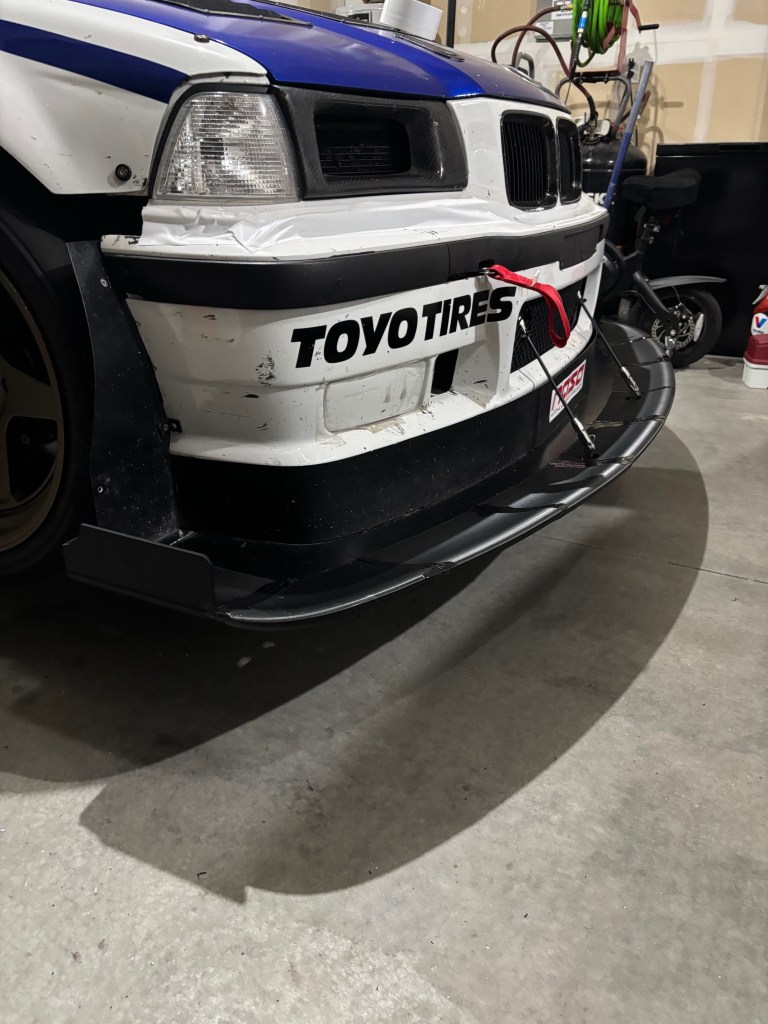
James Mewett also thickened and rounded his front splitter lip, and took the following picture.

It’s illuminating to see how the path of air is influenced, so far above and ahead of the splitter. Since the underside of the splitter does the most work, this modification should work really well.
I love I hear success stories like these, so if you’ve fixed your splitter lip (or used any other tips and tricks on this website), contact me and I’ll write up a testimonial.
