I wanted a proper wing for my Veloster, that makes enough downforce to match my splitter. The OEM wing on a Veloster N isn’t really a wing, because it doesn’t have an airfoil shape. It’s not exactly a spoiler either, because air goes both on top and underneath it. What the wing/spoiler does is straightens out airflow and cancels some of the lift created by the downward-sloping roof. It makes downforce, but not enough to counteract a decent splitter.
There are a lot of good off the shelf wings, but I wanted to make my own (again). This time I opted for a Selig S1223 airfoil. There’s a higher lift version called the S1223 RTL, but it really only has an advantage at the steepest angle of attack, and otherwise has less lift.
Designing aero for FWD hatchbacks is new to me, and there’s definitely some guesswork involved. As a rule of thumb, you want the widest wingspan allowed in your racing rules, because this lessens the detrimental effect of wing-tip vortices. Most rules limit wings to body width, which on a Veloster N is 71.3″ (181cm). That’s a large wing, but because front-wheel drive cars have proportionately less weight on the rear of the car, they don’t need as much rear downforce.
I could have made a high aspect ratio wing the full width of the car, but this would result in a very small chord. At Reynolds numbers under 2 million, wings are actually more efficient with more chord, not less. So this is an area where I’m totally stumped: is a narrow wingspan with more chord better or worse than a high aspect ratio? I’ll have to test this one day.
One thing is for sure, a longer wingspan is a pain in the ass (and often a pain in the head) when you work on the car. The number of times I’ve bonked my head or run into an end plate…
So in the end, I decided on a wing with a 53.3″ (135cm) wingspan and 11″ chord, with a total area of 583 square inches. That’s the same total area as a 64″ 9 Lives Racing wing that you’d see on a Miata, which kinda makes sense, as a Miata and Veloster have the same amount of weight on the rear wheels.

I traced the S1223 airfoil shape onto Meranti Hydrotek (BS6566) plywood scraps I had lying around from splitter projects, and then cut them out on my band saw.
Wing construction
I began by gluing up the ribs to a central spar. You can see in the pic that the spar is notched into the wing mounts and end plates. I then glued a wood dowel to the front and a thin spar towards the trailing edge. This skeleton provides the basic structure and shape, so that thin plywood panels can be glued on top and bottom.
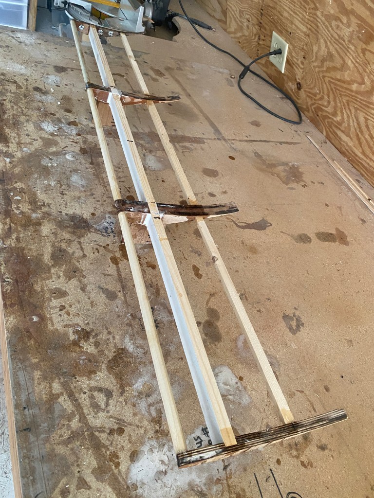
The plywood itself is very thin and offers little strength, but the whole outside will be covered in fiberglass, which is where the strength comes from. This construction style is called a torsion box, and is used on everything from airplane wings to the doors in your house.
The wing mounts are on the bottom, and an integral part of the structure, so I had to laminate the bottom of the wing in three pieces. I did one at a time.
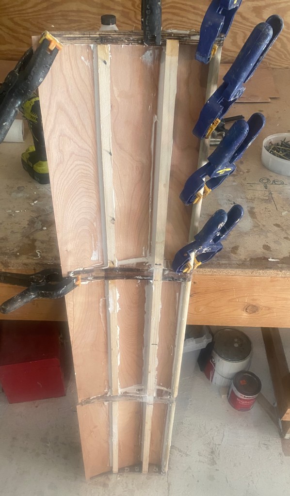
After gluing and filleting the bottom panels using epoxy and microspheres (filler), I flipped the wing over and glued the top of the wing. You might be wondering about the plywood I use for the upper and lower skins. Big box lumber stores like Home Despot and Lowe’s get pallets of wood that are strapped down with a very thin plywood sheet over the top to protect the wood below. This thin 3-ply plywood is so flexible you can almost bend it in a circle. There’s no SKU for it, and they’ll give it away if you ask nicely.
I can make a couple wings from a sheet of this plywood. But while it’s free, it isn’t easy to find, because it doesn’t come on every pallet of wood, and they typically throw it away. So make sure you check back often or make friends with the store manager, this shit is gold.

After gluing on the plywood panels I wrapped the whole thing in fiberglass fabric. After gluing the wing up, I noticed the rear edge of the wing was a little wavy. Damnit. I don’t think this is a big deal for a single element wing, and I’ve even seen some wings that have a wavy rear edge on purpose. But I’m going to add a double element in thr future, and it needs a straight trailing edge for that.
The solution was to clamp and glue a 1/2” (13mm) Gurney flap to help flatten it out. I wasn’t sure I was going to add a wicker on this wing, but it was the obvious solution to this problem and now it’s not coming off!
The wing weighs 6.6 lbs (3 kg) which is pretty light considering how stiff and solid it feels, and this includes the gurney flap, end plates, and bottom mounts. That’s less than half the weight of an aluminum wing of the same size, and probably a pound heavier than a $3000 carbon wing. The bigger difference is my material cost is less than $100.
Wing mounts
While building the wing I spent a lot of time thinking about wing mounts. Many racing rules limit the height of a wing to roof height, but they usually give hatchbacks a bit more room, and 5-8″ above the roof is common. That’s plenty of height considering how much the roof slopes back in the rear.
On a sedan, you typically mount a wing with about 1/4 of the wing overlapping the rear of the trunk. On a hatchback, you need to get the wing a bit further back. The wing needs area below the wing for the low-pressure region to form, and the rear window glass is in the way.
Because I don’t know a lot about hatchback aerodynamics, I want to be able to adjust the wing not only for angle, but for height and setback distance. Because of the high roofline, being able to make adjustments here could be critical.
For this reason, I built a four-point mount with a long, flat top. This allows me to move the wing fore and aft 6”. I also put a 8-degree fixed angle into the top of the cradle mount, and so moving the wing forward or backward changes the height 1”. The wing itself has built-in uprights with an additional 2″ of height adjustment, so altogether I can move the wing forward or backward 6″ and up or down 3″. For the lowest drag settings, I zero out the wing and move it low and forward. For the highest downforce configuration, I’ll move the wing rearward and up. Makes sense to me, but let’s see how it works.

Airfoil data
The following images come from Airfloil Tools and show the S1223 data at 500k Reynolds, which is 57 mph (92 kph) for an 11″ chord wing.
The first graph is the coefficient of drag (Cd) at different angles of attack. The lowest drag setting is right at zero degrees, but anywhere between -2 to +2 degrees is going to be indistinguishable. From 3 degrees to 12 degrees drag increases linearly, but then really spikes upwards at 13 degrees as flow separations occur.

In the next graph you can see the best lift/drag ratio of the wing is around 5 degrees. This isn’t hugely important, since it’s the lift/drag ratio of the vehicle that matters, not the wing. Anyway, it’s an interesting data point.

The most important graph is the coefficient of lift vs angle, because you can use that to estimate the amount of downforce at different angles of attack. This wing ranges between .5 Cl at -2.5 degrees to 2.4 Cl at 13 degrees

Therefore, I’m going to spec a working range of 0 to 12 degrees, and use a baseline of 8 degrees. Now, because the roof also slopes downward at around 8 degrees over the roof extension, that means I’m actually setting the wing to zero degrees in relation to the ground.
Given all this data, it would be useful to have five settings for wing angle: 0, 3, 5, 8, and 12 degrees. In terms of pounds of downforce, if the wing is making 120 lbs of downforce at zero degrees, then each setting would be about +25 lbs of downforce. I don’t think settings in between those will be super useful, as I don’t think I could feel a difference of having 12 pounds more or less in the trunk.
| Angle | Lbs DF |
| Zero | 120 |
| 3 deg | 150 |
| 5 deg | 175 |
| 8 deg | 200 |
| 12 deg | 225 |
Wind tunnel results
I tested this wing in the wind tunnel and it did very well. It made about 180 lbs of rear downforce at 100 mph, and lost about 30 lbs on the front. The loss of front downforce is the natural effect of pushing down on the rear of the car, it goes up on the other.
If 180 lbs seems low, it’s because it is. See my previous comments about height, angle, and setback distance. With those variables optimized, I expect to almost double the downforce.
When compared to the other wings I tested, the Selig wing was very efficient. For some reason, this wing lost less front downforce than the other wings I tested, and as a result, the S1223 wing had the highest L/D ratio of all the wings. However, it didn’t make quite as much downforce as the others, so the L/D ratio of the vehicle was slightly worse with this wing than the other wings.
This is exactly why shopping for a wing looking at its efficiency is utterly worthless, because the most important aspect of a wing is how much downforce it makes. If two wings make the same downforce and one has less drag, of course use the one with less drag. If one wing makes more downforce than the other, but it also makes more drag, 99 times out of 100 you want the wing with downforce, as that will make the vehicle the most efficient.
As an airfoil, the S1223 is still a solid choice for a car wing. I’ve recently shifted my focus from low-Reynolds high-lift aviation airfoils to Enrico Benzing’s designs, and the MSHD airfoil. The latter I recently built and tested in the wind tunnel, and I’ll report on that soon. Subscribe to my blog and you won’t miss that. Believe me, you don’t want to miss that.
