Fact: Interaction with the car’s roof can have a large impact on the effectiveness of a wing. Case in point: my 9 Lives Racing wing generated 130% more rear downforce when using a fastback than with the OEM hardtop. Same wing, same height, same angle of attack, more downforce. Put another way, the fastback made my 60″ wing behave as a 78″ wing. Although the converse is closer to the truth, which is that the shape of the OEM hardtop made my 60″ wing behave as a 46″ wing. Ouch. There are at least three reasons for this.
- Less turbulence – Turbulence is bad for wings, it makes less downforce. Here’s proof: when I removed the OEM hard top (making the car into the convertible it was designed to be), I got only 40% of the downforce as the hardtop. Going in the opposite direction, the fastback had less turbulence than the hard top, and that’s where some of the 130% comes from. In other words, you could make anywhere from 40-130 lbs of downforce, at the same speed, from the same wing, just by changing the top and nothing else.
- Air shape – The wing is flat, the roof is not. As air moves over the center of the car, it has to go up over the windshield, across the roof, down the rear window, and then across to the trunk. This creates a large curve, and air follows this curve in what I’ll call downwash angle. In the center of the car, there’s a downwash angle, outside the car where the wing is in clean air, little or none. It’s probable that the fastback flattened the shape of air, making the center of the wing work more similarly to the sides of the wing.
- Better wing angle? – During the testing I did at Watkins Glen, I set the wing angle to 4 degrees. When I swapped roofs, I didn’t adjust wing angle. If I’d spent time optimizing wing angle for each roof, this might have made a difference. But I had other things to test and didn’t have time. 9 Lives Racing’s CFD shows that the wing stalls at 5 degrees with an OEM hard top, which is fairly close to what I measured, and so the wing should have been nearly at peak downforce behind the hardtop. However, it’s possible the fastback gave a more optimal wing angle due to a different downwash angle of air. Or it could have been worse, I don’t know. I just don’t want to leave this stone unturned.
The easiest way to mitigate all of these differences is to get the wing as high as possible, where the air is less affected everything in front of it. While the wing may make more downforce in this configuration, the car may not (based on the rear wake and and if it has a diffuser). There are other problems with wings that are too high, but that’s a different article.
I typically mount my wings at roof height, which is a good baseline. But some racing rules limit wing height to substantially less than roof height (SCCA ST) in which case the shape of the roof is going to have a big impact on the effectiveness of the wing.
3D-wings solve this problem by having a center section that has less angle than the ends. But how do you know the shape of air? How wide should the center section be, and how much offset should there be between the center angle and the ends? I mean, it’s got to be different for every car!
Making a 3D wing is expensive and requires composite materials, and a company like APR Performance isn’t going to make a 3D wing that is optimized for each and every car. It just wouldn’t be economically feasible. Instead, they make a few wings that cover typical applications for most cars. The width of the center section, and the offset between middle and ends, are going to be happy mediums.

Let’s take a look at some sexy carbon fibre APR wings.
- The APR GTC-500 is 71″ or 74″, has a 10-degree offset. APR designed this wing for cars with a low-angle fastback, such as a Corvette, NSX, etc.
- The APR GTC-300 comes in 61″ and 65″ and has a 15-degree offset. According to APR, this wing is designed for widebody sports and touring cars. This wing has a very narrow cross section.
- The GTC-200 comes in two versions, the original 59.5″ with a 12-degree offset, and a newer 60.5″ with 14-degree offset. I have the 59.5” version, and I’ll get in the details on this one later. According to APR, these wings are designed for sports and compact cars.
Miatas are listed as one of the applications for the GTC-200. Since APR is suggesting the GTC-200 for Miatas, we can conclude that they think there’s a 12-14 degree difference in downwash angle between the center of the car and the outsides. That’s a huge difference!
If you look at CFD for different wing shapes, you’ll see most wings operate most efficiently in a pretty narrow range, between 0-10 degrees angle of attack. What APR is telling us with a 12-14 degree offset in the middle of the wing, is that a 2D wing on a Miata will stall in the middle of the wing. Indeed, this stall condition was corroborated by CFD done by the Hancha Group.
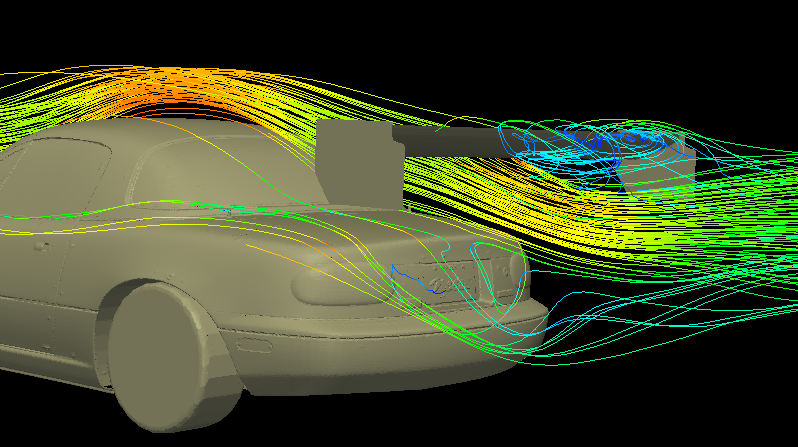
In the picture, notice how air coming down the Miata’s roof effectively increases the angle of attack on the wing. This downwash angle is less at the sides of the wing, and more in the center. The blue lines indicate that there’s a stall condition in the middle of the wing. Stall means more drag and less lift; it’s bad.
9 Lives Racing did their own CFD, and in it they found their wing stalled at around 5 degrees behind a Miata hard top. Based on the profile of the wing (which is similar enough to a CH-10-48-13, which stalls at around 10 degrees), we can conclude that the downwash angle on a Miata OEM hard top is around 5 degrees at roof height. Does that mean 9 Lives Racing’s CFD, or APRs wing design is wrong? No. APRs wing mounts are lower, and the downwash angle is greater closer to the trunk.
In my own testing with a DIY airflow visualizer I measured a 5-7 degree downwash angle at roof height, the greatest angle was just inside the wing stands, whereas in the middle of the roof it was flatter, at about 5 degrees. When I lowered the airflow visualizer to half height, the angle in the middle increased over the span, to about 15-degrees near the trunk. So, that means me, 9 Lives Racing, and APR are all in general agreement about the downdraft angle. Good.
APR GTC-200
I own a GTC-200, let’s take a look. They have a website with data, which APR has a lot of. They show streamlines and pressure plots, but mostly from the top-side of the wing. The suction side of the wing does more work, but they mostly ignore that. I’m also not sure what to make of pressure plots anyway. While they are colorful and look impressive, I don’t know how that translates to anything useful, like lift and drag.
They did CFD analysis and give results in spreadsheet form, which pleases me. However, the CFD appears to be done entirely in free-stream air, which completely misses the point of a 3D wing! They mention this in their explanation of how to read CFD, and this is how they put it: “Basically, this airfoil was never intended to be used in this CFD simulation’s environment of free-stream air.” Totally agree. So why do it?
If I were comparing two wings in free stream CFD, one a 3D wing, and another a 2D wing, I’d expect the 2D wing to perform better. Likewise, in the real world, I would expect a properly designed 3D wing to outperform a 2D wing.
| I was going to include a CFD analysis here, but got cock blocked. The APR has a disclaimer on their website: The information contained herein is property of APR Performance, and may not be reproduced in whole or in part without prior written consent from APR Performance. I emailed them to ask permission to use this data and never got a reply. |
APR have a blurb on their website that says nobody can republish their CFD without permission. I asked for permission, but they never emailed me back. I also emailed to get new end plugs and they didn’t email me back. Lame on both counts.
Since I don’t have permission to use their public data, I’ll look at my own wing. The GTC200 chord measures around 8.5″ in the middle of the wing, 7″ at the extreme ends, and averages around 8″ across its 59.5″ length. The cross-section shape of the middle of the GTC200 is shown below. I went to Airfoil Tools to find a similar shape and came away with a lot of things that are similar, but because of the chubby tail section, nothing was a really good match.

For kicks, I’ll take a look at some numbers for a Gottingen 222 airfoil, which is not dissimilar from the shape of the middle of the wing. When I examine the numbers for the usual 200k, 500k, 1M Re plots (Ncrit = 5), I see a good all-purpose wing.
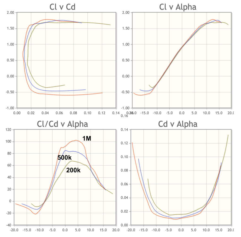
In the 500k Re range (78 mph at mid chord), the wing is most efficient at 0 degrees, but 3-5 degrees seems like the sweet spot for a range of speeds. The wing stalls around 12 degrees, where lift goes down and drag goes way up.
The ends of the wings taper in chord, and there’s a radical change in shape for the last 10 inches. Just looking at the profile on the ends of the wing, I would imagine there’s flow separation or at least turbulence at the trailing edge with this much upsweep and angle. But I’m not a professional aerodynamicist, and I trust they did their homework. It might even be that some turbulence or separation at the ends is desirable to cancel a trailing vortex. Smarter people than me designed this.

I’m curious to see if I can find an airfoil shaped like the ends of the wing, and the closest I can find is the Gottingen 531, which, if I increase the thickness to 140 percent, is not the same, but in the same family of weird.

While this isn’t the same profile, it’s the closest I can find, and I want to see what the numbers look like. I probably should have left off the 1M plot (orange), since that represents this wing traveling at over 180 mph! But if I look at Re 200k and 500k, this shape can take a lot of angle without stalling (see the blue arrow), and 12-14 degrees actually does seem OK (recall this is the offset from the main wing). However, there’s a lot of drag at this steep of an angle.

Given all this data, I’d mount the wing 6-8” off the trunk surface. If it’s higher than that, the downdraft angle changes, and the 3D shape of the wing no longer matches what’s coming down off the roof. I’d set the angle in the center of the wing to zero degrees. If set to more than 3 degrees, the wing ends will stall, creating less downforce and a lot more drag.
Roof-height 3D wing
To be perfectly honest, I’m not crazy about APRs GTC200 wing. I don’t like the profile in the middle or the ends of the wing, and anything with a rounded trailing edge is highly suspect. I also don’t want to mount a wing close to the trunk, because you need space for the negative pressure zone under the wing.
I’d much prefer a 3D wing with a different shape, and I’d mount it at about roof height. There isn’t really anything like that in the market, but it would be simple to build one. If I created a custom 3D wing for a Miata, how much better would it be than a 2D wing?
It’s not that difficult to figure out using existing data. If we say half of the wing is working in the desired range, and the other half is working 5 degrees off (at roof height) we already know the following.
- If you set the wing to 10 degrees, the ends of the wing will be at max downforce, but the middle of the wing will be effectively at 15 degrees. At this angle, the middle of the wing is stalling, and drag goes way up. This setting has a lot of downforce, but at the cost of too much drag. Don’t do it.
- A better setting for maximum downforce is to set the wing to 5 degrees, then the outsides are working in a good range and the middle is essentially at 10 degrees. This gives about the same downforce as above, but a lot less drag. I wouldn’t set a wing to more than this.
- If you set the wing to zero degrees, then the middle is making good downforce at 5 degrees, and the sides are at peak efficiency (zero). This is a good all-purpose setting.
- You could also set the wing to a couple degrees negative, which would be the wing’s highest lift/drag ratio, but your car would go slower around every track that isn’t a high-speed oval.
Note: The wing ends, meaning the area outside of the wing mounts, accounts for 36% of the total area, but because the air is less turbulent here, they produce more downforce by comparison. That’s why I’m saying that half the wing is working in the desired range, even if it’s a 36/64 split.
Using published CFD data, let’s see how a 2D and 3D wing optimized for roof height mounting would compare at 100 mph.
| Wing angle | DF | Drag | L/D |
| 2D 0 deg | 153 | 11.5 | 13.35 |
| 3D 0 deg | 126 | 9 | 14 |
| 2D 5 deg | 190 | 17 | 11.18 |
| 3D 5 deg | 181 | 14 | 12.93 |
| 2D 10 deg | stall | lots | who cares? |
| 3D 10 deg | 199 | 20 | 9.95 |
So, is a 3D wing on a Miata worth it? Barely.
At zero degrees, the 3D wing has a 5% better L/D ratio. At 5 degrees AOA, it’s about 14% better. I don’t usually look at the efficiency of a wing, because it’s the efficiency of the entire vehicle that matters, and that figure is generally the highest when the wing is making the most downforce. So how much more downforce can you get out of a 3D wing? About 5%.
That’s not very much, and because Miatas are front-downforce limited, you’re not going to get a lot of performance out of adding more in the rear. But on a low powered car, on a high speed track, then a small reduction in drag for the same amount of downforce can be marginally useful.
I’m toying with the idea of making a DIY 3D wing with Miata-specific dimensions. I’d increase the chord to 12” and maybe use a reverse swan mount. With that much rear downforce I’d need to optimize the shit out of the splitter. But that’s already in the works.

Great article. I’m currently finishing a slightly 3D wing with a 12″-13″ chord and reverse swan mount (reverse from convention but I consider it a forward swan mount and all others are reverse, as swans don’t often move backwards… I assume). Mounting it to a GR Supra which has a pretty low angle fast-back shape. First track test in 3 weeks. I was thinking that an easy DIY option could be to use a 2D aluminum element (like 9-lives) and cut/rotate/weld the outboard ends to the desired angular offset. Keep up the great content.
LikeLiked by 1 person
We are on the same page with that 3D from a 2D design. Looking forward to hearing how it works.
LikeLike